E-waste management addresses the growing challenge of handling discarded electronic devices in a safe and sustainable manner. To understand this issue, it is important to know what is e-waste and how rapid technological advancement increases electronic waste generation. Identifying the types of e-waste helps in sorting and handling different electronic components effectively. Proper e-waste classification supports safe handling, treatment, and compliance with environmental regulations. An efficient e-waste recycling process ensures recovery of valuable materials while reducing environmental pollution. Moreover, electronic waste recycling plays a vital role in conserving natural resources and minimizing health risks. Effective e-waste management promotes environmental protection, resource efficiency, and sustainable development in modern societies.
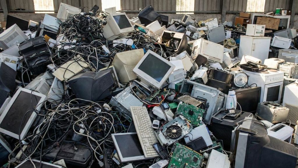
India ranked third in the world in terms of E-waste production last year, behind China (10.1 million tonnes) and the United States (3.2 million tonnes) (6.9 million tonnes). Consumers waste 44 million tonnes of electronics per year, according to a 2019 United Nations study titled “A New Circular Vision for Electronics, Time for a Global Reboot,” and just 20% of that is recycled sustainably. According to the Global E-Waste Monitor 2020, customers discarded 53.6 million tonnes of electronics in 2019, an increase of 20% over the previous five years.
Shocking right? Can you imagine tonnes and tonnes of E-waste piling up? Think of the damage it would do to our mother nature. But what if I say there’s an alternative? Yes, you heard me right. I am talking about recycling or management of the Electronic-waste.
In this blog, I will walk you through Electronic-waste management , different types and its recycling process.
- What is e-waste ?
- Significance Electronic waste management and recycling
- E-waste recycling process
- Benefits of Recycling
- Key Takeaways
- Conclusion
What is e-waste ?
E-waste, or electronic waste, refers to discarded electrical and electronic equipment that is no longer usable, repairable, or required. Common examples include computers, mobile phones, televisions, household appliances, and office electronics. As technology evolves rapidly, the generation of electronic-waste continues to increase worldwide. Improper disposal of e-waste can release harmful substances such as lead, mercury, and cadmium into the environment, posing serious risks to human health and ecosystems. Proper handling and recycling of e-waste allow the recovery of valuable materials like metals and plastics while reducing environmental pollution. Understanding what e-waste is helps promote responsible disposal practices and supports sustainable waste management solutions.
Types or classifications of e-waste
Types of e-waste are classified based on the nature, size, and function of electronic equipment. Proper classification helps in safe handling, efficient recycling, and environmentally responsible e-waste management practices.
The European Directive on Waste Electrical and Electronic Equipment divides waste into ten categories:
- Small household appliances
- IT equipment (including monitors)
- Consumer electronics (including TVs)
- Lamps
- Luminaires
- Toys
- Tools
- Medical devices
- Monitoring and Control Instruments,
- Automatic dispensers
Let me brief about the importance of recycling E-waste.
Significance Electronic waste management and recycling
E-waste management is essential in addressing environmental challenges. It also helps with health challenges caused by the rapid growth of discarded electronic devices. Effective electronic waste recycling helps recover valuable materials, reduces pollution, and supports sustainable development by ensuring safe handling and proper disposal of electronic waste.
E-waste management is incomplete without recycling. Let’s see the reasons.
- The aim of extracting metals and plastic from electronic waste is to use them in the manufacture of new electronics.
- Recycled metals are two to ten times more energy-efficient than metals smelted from raw ore.
- It’s used in tablets, smartphones, and electric car batteries.
- According to the most recent estimates, the global value of e-waste is about $62.5 billion per year, which is more than the GDP of most countries. It’s also worth three times what all of the world’s silver mines produce.
- It can significantly minimise the release of radioactive materials into the atmosphere.
- Helps to prevent the depletion of natural resources if properly implemented.
- Reduces exposing workers to toxic and carcinogenic substances like mercury, lead, and cadmium.
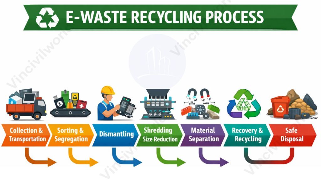
E-waste recycling process
E-waste management depends on a well-structured recycling process that ensures safe handling, efficient material recovery, and environmentally responsible disposal of electronic waste. A step-by-step recycling approach reduces pollution, protects human health, and supports sustainable resource utilization.
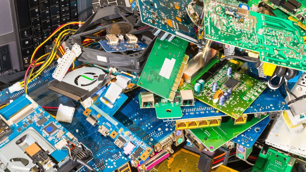
Recycling printed circuit boards from electronic waste is one of the most difficult tasks. Gold, silver, platinum, and other precious metals, as well as base metals like copper, iron, and aluminium, are used on the circuit boards.
Some of the ways of processing e-waste includes:
- Melting circuit boards
- burning cable sheathing to retrieve copper wire
- open-pit acid leaching
Mechanical shredding and separation is the traditional process, but the recycling efficiency is poor. Cryogenic decomposition is an alternative method for recycling printed circuit board.
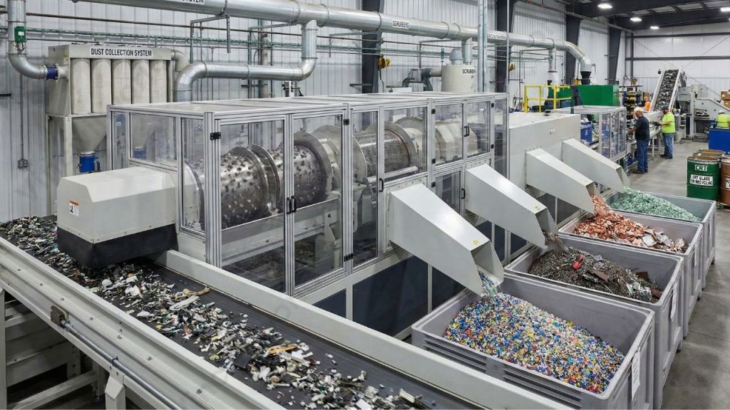
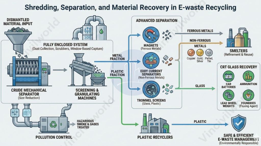
Shredding, Separation, and Material Recovery in E-waste Recycling
- After dismantling, the material for shredding is conveyed into a crude mechanical separator, where size reduction begins. This stage plays a critical role in effective e-waste management by preparing materials for accurate separation.
- The system uses screening and granulating machines to separate the constituent metal and plastic fractions. Once separated, these fractions are directed toward appropriate recovery streams and are sold to smelters or plastic recyclers for further processing.
- This type of recycling equipment is fully enclosed and fitted with a dust collection system to prevent airborne contamination. Additionally, scrubbers and window-based capture systems collect a portion of the pollutants generated during shredding and granulation.
- Following this, glass, plastic, and ferrous and non-ferrous metals are isolated using magnets, eddy current separators, and Trommel screens. These materials undergo further refinement at smelters.
- CRT glass is recycled into products such as car batteries, ammunition, and lead wheel weights, or sold to foundries for use as a fluxing agent in raw lead ore production. Valuable metals including copper, gold, palladium, silver, and tin are recovered and sold to smelters for reuse.
- To protect the atmosphere, hazardous smoke and gases are detected, contained, and treated. Through these techniques, all useful device construction materials are safely reclaimed, ensuring environmentally responsible and efficient e-waste management.
Also read : Air pollution – effects and causes
Benefits of Recycling
- The most successful solution to the growing e-waste issue is to recycle raw materials from end-of-life electronics.
- Recycling preserves our natural resources.
- Dismantling and reuse options prevent air and water contamination induced by hazardous disposal.
- Furthermore, recycling decreases the amount of greenhouse gas emissions generated by new product production.
Key Takeaways
- E-waste management addresses the safe handling and disposal of discarded electronic devices.
- Rapid technological advancement has significantly increased global electronic waste generation.
- India ranks among the top e-waste–producing countries, highlighting the urgency of proper management.
- Understanding what is e-waste helps promote responsible disposal and recycling practices.
- Proper types and classification of e-waste support efficient collection and treatment.
- Recycling enables recovery of valuable metals such as gold, copper, and silver.
- Effective electronic waste recycling reduces environmental pollution and health risks.
- Advanced recycling processes improve material recovery efficiency.
- E-waste recycling conserves natural resources and saves energy.
- Sustainable e-waste management supports environmental protection and circular economy goals.
Conclusion
E-waste management has become a critical environmental priority due to the rapid growth of discarded electronic devices worldwide. Understanding what e-waste is, along with its classification and recycling methods, helps address the environmental and health challenges associated with improper disposal. Efficient electronic waste recycling recovers valuable materials, reduces pollution, and minimizes the release of toxic substances into air, soil, and water. In countries like India, where e-waste generation is rising sharply, strong regulations and public awareness play a vital role in effective implementation. By adopting structured recycling processes and responsible consumption habits, societies can conserve resources, reduce energy use, and promote sustainable development.
Proper e-waste management is essential for protecting ecosystems and ensuring a cleaner, healthier future. Considering the huge volume of E-waste generated everyday recycling them is the need of the hour. India has formulated and notified its strategy to tackle e-waste through the e-waste (Management) Rules, 2016. Recycling reduces pollution, saves energy and conserves resources.
That’s it about E-waste. Hope you found it useful.