When it comes to protecting your property, investing in roofing in Sugar Land is essential. The local climate, known for intense heat, humidity, and seasonal storms, puts constant pressure on roofs. Over time, even small issues can escalate if ignored. That is why working with a skilled roofing contractor is crucial to ensure long-term durability and safety.
Texas continues to rank among the top states for weather-related property damage. According to the Insurance Information Institute, hailstorms alone cause billions in losses each year across the state. This makes regular maintenance and timely roof repair a necessity for homeowners and businesses alike.
Severe weather can strike without warning, making emergency roofing support an important service. Strong winds and heavy rain often lead to leaks, damaged shingles, or weakened structures. Addressing these problems quickly helps prevent further complications.
A professional roofing company can assess the condition of your roof and recommend the right solution, whether it is a minor fix or a more extensive repair. The National Oceanic and Atmospheric Administration notes that Texas experiences hundreds of severe storm events annually.
This highlights the importance of having access to reliable roofing services when you need them most.
Routine inspections are equally important. They help identify hidden damage early and extend the overall lifespan of your roof while maintaining energy efficiency.
Choosing Reliable Roofing Experts
Finding the right professionals for roofing in Sugar Land can make a significant difference in the outcome of your project. For homeowners looking for dependable roofing in Sugar Land with fast response and expert workmanship, Madison Roofing stands out as trusted local roofing experts in Sugar Land providing solutions tailored to both residential and commercial needs. Their experienced team focuses on restoring safety, functionality, and long-term performance.
Working with experienced contractors ensures high-quality materials, proper installation, and clear communication throughout the process. This ultimately saves time, money, and stress.
Sugar Land is a vibrant city known for its family-friendly neighborhoods, growing economy, and attractions like Sugar Land Town Square and Cullinan Park. The area experiences long, hot summers and occasional severe storms, both of which can impact roofing systems. These environmental factors make durable and weather-resistant roofing a must for homeowners in the region.
Across Texas, more property owners are choosing energy-efficient roofing materials. Reflective roofing systems are becoming popular due to their ability to reduce heat absorption. According to the U.S. Department of Energy, these materials can lower roof temperatures by up to 50°F, helping reduce cooling costs.
A strong roof is one of the most important investments you can make for your property. From handling urgent issues to planning long-term care, working with experienced professionals ensures your home stays protected. With the right approach, roofing in Sugar Land can provide lasting value, safety, and peace of mind.
E-waste management addresses the growing challenge of handling discarded electronic devices in a safe and sustainable manner. To understand this issue, it is important to know what is e-waste and how rapid technological advancement increases electronic waste generation. Identifying the types of e-waste helps in sorting and handling different electronic components effectively. Proper e-waste classification supports safe handling, treatment, and compliance with environmental regulations. An efficient e-waste recycling process ensures recovery of valuable materials while reducing environmental pollution. Moreover, electronic waste recycling plays a vital role in conserving natural resources and minimizing health risks. Effective e-waste management promotes environmental protection, resource efficiency, and sustainable development in modern societies.
India ranked third in the world in terms of E-waste production last year, behind China (10.1 million tonnes) and the United States (3.2 million tonnes) (6.9 million tonnes). Consumers waste 44 million tonnes of electronics per year, according to a 2019 United Nations study titled “A New Circular Vision for Electronics, Time for a Global Reboot,” and just 20% of that is recycled sustainably. According to the Global E-Waste Monitor 2020, customers discarded 53.6 million tonnes of electronics in 2019, an increase of 20% over the previous five years.
Shocking right? Can you imagine tonnes and tonnes of E-waste piling up? Think of the damage it would do to our mother nature. But what if I say there’s an alternative? Yes, you heard me right. I am talking about recycling or management of the Electronic-waste.
In this blog, I will walk you through Electronic-waste management , different types and its recycling process.
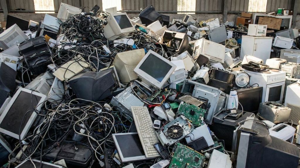
E-waste, or electronic waste, refers to discarded electrical and electronic equipment that is no longer usable, repairable, or required. Common examples include computers, mobile phones, televisions, household appliances, and office electronics. As technology evolves rapidly, the generation of electronic-waste continues to increase worldwide. Improper disposal of e-waste can release harmful substances such as lead, mercury, and cadmium into the environment, posing serious risks to human health and ecosystems. Proper handling and recycling of e-waste allow the recovery of valuable materials like metals and plastics while reducing environmental pollution. Understanding what e-waste is helps promote responsible disposal practices and supports sustainable waste management solutions.
A large pile of discarded electronic devices, highlighting the growing issue of e-waste.
Types or classifications of e-waste
Types of e-waste are classified based on the nature, size, and function of electronic equipment. Proper classification helps in safe handling, efficient recycling, and environmentally responsible e-waste management practices.
The European Directive on Waste Electrical and Electronic Equipment divides waste into ten categories:
Small household appliances
IT equipment (including monitors)
Consumer electronics (including TVs)
Lamps
Luminaires
Toys
Tools
Medical devices
Monitoring and Control Instruments,
Automatic dispensers
Let me brief about the importance of recycling E-waste.
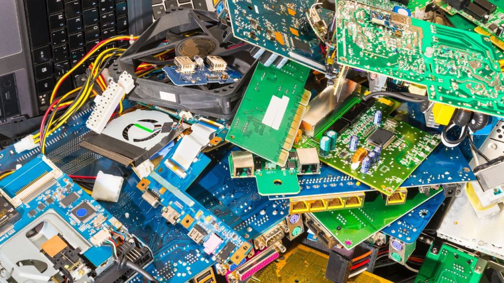
A close-up view of various electronic waste components, illustrating the complexity and volume of e-waste generated in modern society.
Significance Electronic waste management and recycling
E-waste management is essential in addressing environmental challenges. It also helps with health challenges caused by the rapid growth of discarded electronic devices. Effective electronic waste recycling helps recover valuable materials, reduces pollution, and supports sustainable development by ensuring safe handling and proper disposal of electronic waste.
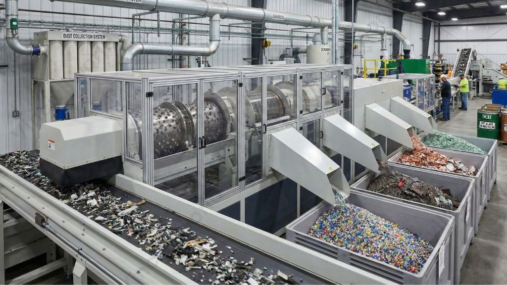
An advanced e-waste recycling facility showcasing the shredding and separation process for efficient electronic waste management.
E-waste management is incomplete without recycling. Let’s see the reasons.
The aim of extracting metals and plastic from electronic waste is to use them in the manufacture of new electronics.
Recycled metals are two to ten times more energy-efficient than metals smelted from raw ore.
It’s used in tablets, smartphones, and electric car batteries.
According to the most recent estimates, the global value of e-waste is about $62.5 billion per year, which is more than the GDP of most countries. It’s also worth three times what all of the world’s silver mines produce.
It can significantly minimise the release of radioactive materials into the atmosphere.
Helps to prevent the depletion of natural resources if properly implemented.
Reduces exposing workers to toxic and carcinogenic substances like mercury, lead, and cadmium.
E-waste recycling process
E-waste management depends on a well-structured recycling process that ensures safe handling, efficient material recovery, and environmentally responsible disposal of electronic waste. A step-by-step recycling approach reduces pollution, protects human health, and supports sustainable resource utilization.
Recycling printed circuit boards from electronic waste is one of the most difficult tasks. Gold, silver, platinum, and other precious metals, as well as base metals like copper, iron, and aluminium, are used on the circuit boards.
Some of the ways of processing e-waste includes:
Melting circuit boards
burning cable sheathing to retrieve copper wire
open-pit acid leaching
Mechanical shredding and separation is the traditional process, but the recycling efficiency is poor. Cryogenic decomposition is an alternative method for recycling printed circuit board.
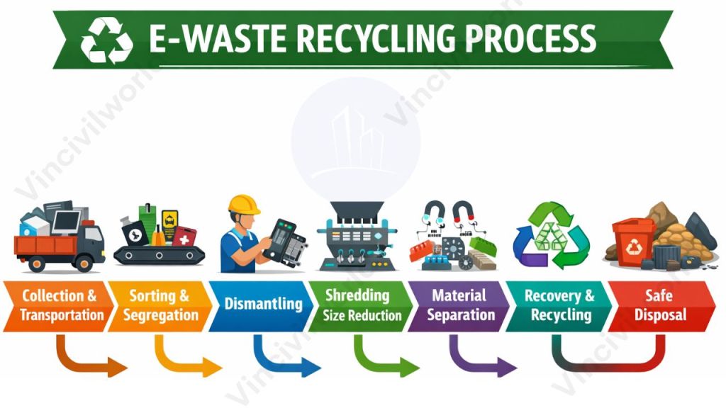
Illustration of the E-waste recycling process, highlighting key steps like collection, sorting, dismantling, shredding, material separation, recovery, and safe disposal.
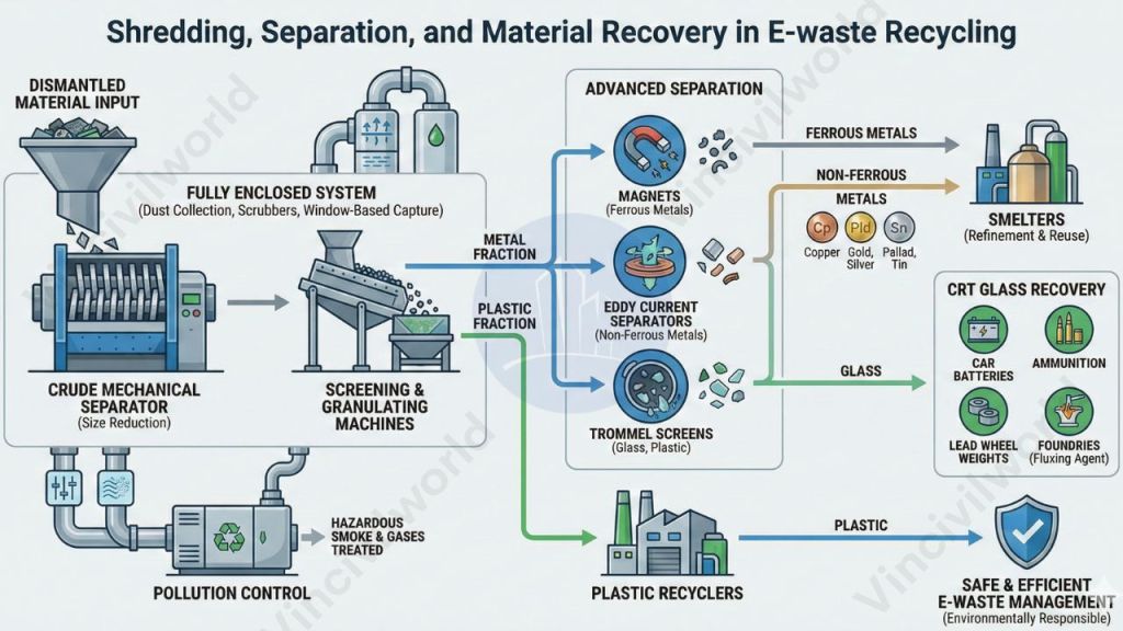
Shredding, Separation, and Material Recovery in E-waste Recycling
After dismantling, the material for shredding is conveyed into a crude mechanical separator, where size reduction begins. This stage plays a critical role in effective e-waste management by preparing materials for accurate separation.
The system uses screening and granulating machines to separate the constituent metal and plastic fractions. Once separated, these fractions are directed toward appropriate recovery streams and are sold to smelters or plastic recyclers for further processing.
This type of recycling equipment is fully enclosed and fitted with a dust collection system to prevent airborne contamination. Additionally, scrubbers and window-based capture systems collect a portion of the pollutants generated during shredding and granulation.
Following this, glass, plastic, and ferrous and non-ferrous metals are isolated using magnets, eddy current separators, and Trommel screens. These materials undergo further refinement at smelters.
CRT glass is recycled into products such as car batteries, ammunition, and lead wheel weights, or sold to foundries for use as a fluxing agent in raw lead ore production. Valuable metals including copper, gold, palladium, silver, and tin are recovered and sold to smelters for reuse.
To protect the atmosphere, hazardous smoke and gases are detected, contained, and treated. Through these techniques, all useful device construction materials are safely reclaimed, ensuring environmentally responsible and efficient e-waste management.
Diagram illustrating the shredding, separation, and material recovery processes in e-waste recycling.
E-waste management addresses the safe handling and disposal of discarded electronic devices.
Rapid technological advancement has significantly increased global electronic waste generation.
India ranks among the top e-waste–producing countries, highlighting the urgency of proper management.
Understanding what is e-waste helps promote responsible disposal and recycling practices.
Proper types and classification of e-waste support efficient collection and treatment.
Recycling enables recovery of valuable metals such as gold, copper, and silver.
Effective electronic waste recycling reduces environmental pollution and health risks.
Advanced recycling processes improve material recovery efficiency.
E-waste recycling conserves natural resources and saves energy.
Sustainable e-waste management supports environmental protection and circular economy goals.
Conclusion
E-waste management has become a critical environmental priority due to the rapid growth of discarded electronic devices worldwide. Understanding what e-waste is, along with its classification and recycling methods, helps address the environmental and health challenges associated with improper disposal. Efficient electronic waste recycling recovers valuable materials, reduces pollution, and minimizes the release of toxic substances into air, soil, and water. In countries like India, where e-waste generation is rising sharply, strong regulations and public awareness play a vital role in effective implementation. By adopting structured recycling processes and responsible consumption habits, societies can conserve resources, reduce energy use, and promote sustainable development.
Proper e-waste management is essential for protecting ecosystems and ensuring a cleaner, healthier future. Considering the huge volume of E-waste generated everyday recycling them is the need of the hour. India has formulated and notified its strategy to tackle e-waste through the e-waste (Management) Rules, 2016. Recycling reduces pollution, saves energy and conserves resources.
That’s it about E-waste. Hope you found it useful.
The activated sludge process is a widely used and highly effective method in wastewater treatment, employing aerobic microorganisms to remove organic pollutants efficiently. This guide covers the activated sludge process definition, stages, and diagram, while explaining its role in secondary wastewater treatment for producing high-quality effluent. You will understand how aeration tanks, wastewater treatment microorganisms, mixed liquor suspended solids (MLSS), and return activated sludge (RAS) work together to maintain stable and efficient system performance. The activated sludge process in wastewater treatment relies on proper aeration, controlled sludge recycling, and effective process monitoring. Due to its reliability, adaptability, and high treatment efficiency, activated sludge wastewater treatment remains the preferred choice for many municipal and industrial wastewater treatment plants, ensuring consistent performance and environmental compliance.
Activated Sludge Process is a globally used wastewater treatment technique. In the previous blogs, I had shown you the various secondary wastewater treatment techniques. In this blog, we will dig deep into this widely used technique of activated sludge process, its configuration, process control and aeration methods.
Activated sludge Process – Definition
The activated sludge process is a type of wastewater treatment that uses aeration. It involves a biological floc made up of bacteria and protozoa to clean sewage or industrial waste waters. This process is biological and has various applications. It includes oxidising carbonaceous biological matter. Additionally, it deals with nitrogenous waste in the biological matter, mostly ammonium and nitrogen.
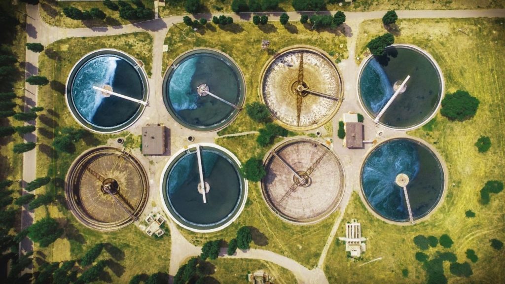
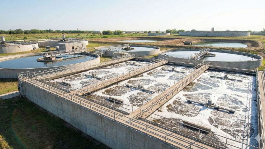
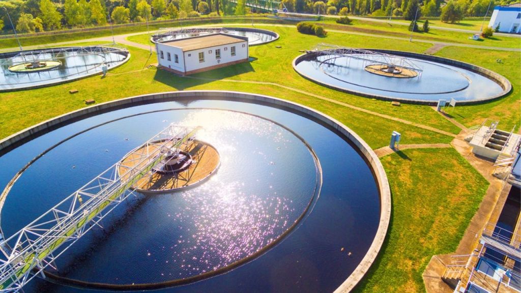
Aerial view of multiple aeration tanks used in the activated sludge process for wastewater treatment.
The activated sludge process employs aerobic microorganisms that can digest organic substances in sewage. Also, they have the ability to cluster together via flocculation. The flocculated particles settle out as sludge. As a result, the liquid coming out is relatively free of suspended solids and organic matter.
Activated Sludge Process – Stages, Configuration, and Diagram
The activated sludge process is a widely used secondary wastewater treatment method. It removes carbonaceous organic pollution through aerobic biological activity. The configuration of an activated sludge wastewater treatment system consists of interconnected units that operate together to ensure efficient treatment.
Aeration Tank
The aeration tank is the heart of the activated sludge process in wastewater treatment. Primary treated sewage is mixed with microorganisms, forming mixed liquor suspended solids (MLSS). Air or oxygen is supplied using diffusers or mechanical aerators to support aerobic microbes. These microorganisms consume organic matter and convert it into stable end products.
Secondary Settling Tank (Secondary Clarifier)
The mixed liquor flows into the secondary settling tank, where biological flocs settle by gravity. Clarified effluent overflows for further treatment or discharge. Settled sludge collects at the bottom.
Sludge Recycling System
A portion of the settled sludge is returned as Return Activated Sludge (RAS) to maintain microbial concentration in the aeration tank. Excess sludge is removed as Waste Activated Sludge (WAS) to control sludge age and system stability.
Advanced control systems regulate aeration, sludge recycling, and flow rates, ensuring stable and efficient secondary wastewater treatment performance.
Now, how about looking deep into what happens inside an activated sludge process?
Diagram illustrating the activated sludge process, featuring the aeration tank, secondary clarifier, mixed liquor, return activated sludge (RAS), and waste activated sludge (WAS) pathways.
Activated Sludge Process Steps
The activated sludge process operates through a series of well-defined stages that enable effective secondary wastewater treatment. Each stage supports biological activity, sludge separation, and recycling to achieve high organic pollutant removal and regulatory compliance.
After primary treatment, wastewater enters into an aeration tank. A portion of sludge from the secondary settling tank also enters.
Organic matter comes into close contact with sludge from the secondary settling tank. Sludge is densely populated with microorganisms that are actively growing.
Diffusers or surface aerators inject air in the form of bubbles into the sewage-sludge mixture.
Microorganisms break down organic matter into stable chemicals like NO3, SO4, and CO2 while also producing new bacterial cells.
The effluent along with the actively growing microbial population passes to the secondary settling tank.
The secondary settling tank separates the aeration tank’s effluent, which contains flocculent microbial matter into supernatant and sludge. The treated supernatant undergoes further treatment before discharge.
This sludge from the settled waste returns to the aeration system’s inlet to re-seed the new wastewater reaching the tank. Return activated sludge (R.A.S.) is the fraction of the floc that returns to aeration tank.
The remaining sludge goes to sludge digesters for further treatment and safe disposal.
“Mixed liquor” refers to the combination of the liquid and microorganisms in the aeration tank. The suspended solids are called “Mixed Liquor Suspended Solids” (MLSS).
In the next section, we will find out the basic process control parameters in an activated sludge process.
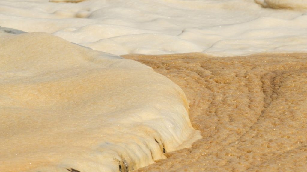
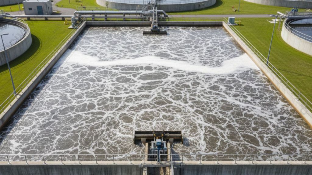
Foamy surface of wastewater during the activated sludge process, illustrating the aeration and microbial activity involved in organic matter treatment.
Process Control in Activated Sludge Process
The general process control method monitors the following variables:
Sludge Volume Index (SVI)
Mean Cell Residence Time (MCRT)
Food to Microorganism Ratio (F/M)
Dissolved oxygen (DO)
Biochemical oxygen demand (BOD)
Chemical oxygen demand (COD)
Let me explain these parameters in detail.
Sludge Volume Index
Sludge Volume Index measures the volume of settled sludge in milliliters. This volume is occupied by 1g of dry sludge solids after 30 minutes of settling in a 1000 milliliter graduated cylinder. It gives a measure of the settling ability of the sludge. SVI ranges from 40 to 100 for a good sludge which settles down easily. Bulking Sludge is a biomass consisting of filamentous organisms with very poor settling characteristics. For a bulking sludge, SVI value can exceed 200. Sufficient pH control, adequate aeration and addition of hydrogen peroxide to the aeration tank prevents bulking.
Mean Cell Residence Time
Mean Cell Residence Time is the ratio of total mass (lbs) of mixed liquor suspended solids in the aerator and clarifier to the mass flow rate (lbs/day) of mixed liquor suspended solids leaving as final effluent.
Food to Microorganism Ratio
The Food to Microorganism Ratio indicates how much organic matter is fed to the microorganisms each day. It is relative to the mass of microorganisms under aeration. In other words, it is the ratio of the amount of BOD fed to the aerator (lbs/day). It is compared with the amount (lbs) of Mixed Liquor Volatile Suspended Solids (MLVSS) under aeration.
Main Control Parameters
The mean cell residence time and F/M Ratio are the main control parameters used industrially. Both are directly related to the effluent quality. However, it is tedious to control the plant on the basis of the F/M ratio since it necessitates a lot of laboratory work to find the BOD and MLSS in the system. Therefore, the mean cell residence time is the best choice for controlling an activated sludge system.
Now you got an idea about the entire process and its important parameters. Next, we move on to the various aeration methods.
Aeration Methods in Activated Sludge Process
The decomposition of organic waste requires a very high concentration of oxygen at the initial stages of contact between microorganisms and the organic matter. The conventional systems usually maintain a plug flow hydraulic regime and keeps aeration and a mixing at an uniform rate along the entire tank. As a result, the oxygen concentration drops rapidly in the inlet and this can harm the microbes.
At the outlet, there is a surplus of oxygen which is not necessary and leads to economical losses. In order to match the oxygen supply and demand along the entire journey of wastewater from inlet to outlet, the mode of aeration needs some modifications. Let’s have a look at the different aeration methods in an activated sludge process.
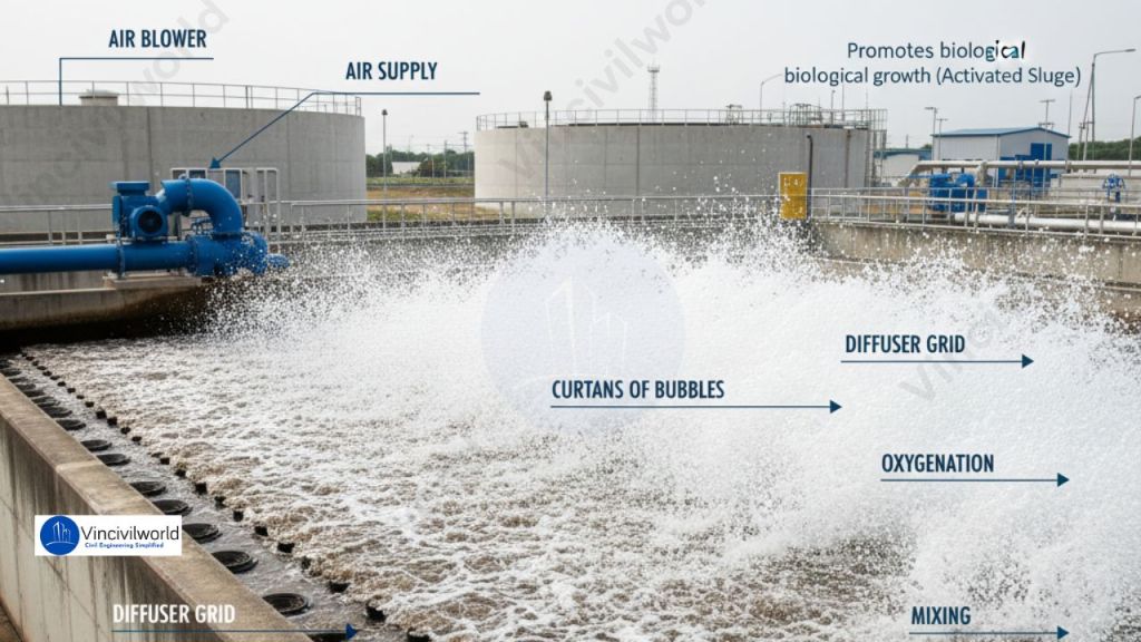
Diffused Aeration
Sewage liquor is pumped into large tanks with floor-mounted diffuser grid aeration devices. Passing air creates a curtain of bubbles that oxygenates the liquor while also mixing it. An air blower usually creates the air. Oxygen replaces air for unusually strong and difficult to treat sewage.
Diffused aeration system in activated sludge process, promoting oxygenation and biological growth.
Tapered Aeration
The organic waste needs more oxygen at the inlet. As it degrades progressively its oxygen demand decreases. Tapered aeration works on this principle. Aeration is intense at the inlet and decreases progressively along the length of the aeration tank. As this method involves the more efficient use of air, it results in savings in the pumping costs too.
Step Aeration
This method aims to equalize the oxygen supply and its demand. It introduces fresh feed at several points in the aeration tank, while keeping the rate of oxygen supply constant. This ensures a more even oxygen distribution over the entire tank and throughout the aeration stage. Baffles divide the aeration tank into several channels with each channel representing one step of the process.
Complete Mix Activated Sludge Process
In complete mix process, the aeration tank receives a mixture of fresh feed and recycled sludge at several locations within the tank. This ensures a constant supply and demand of oxygen along the length of the tank.
Contact Stabilisation
The microbial mass comes in contact with wastewater for short durations of time, approximately 0.5 to 1 hour in the biosorption unit. An anaerobic digestion unit stabilizes the resulting sludge after a retention period of about 2-3 hours. In the digestion unit, microbes consume the organic wastes removed in the biosorption unit. Since we stabilize the return sludge with higher solid concentrations, this reduces the volume of the aeration tank.
Pure Oxygen Activated Sludge Process
This type of activated sludge process supplies pure oxygen instead of air. It recirculates this oxygen into well mixed and converted chambers. Conventional processes utilize only 5-10% of oxygen. In contrast, the pure oxygen activated sludge process ensures about 90% utilization of oxygen. Further, it results in higher bacterial activity, lower sludge volume and sludge with better settling characteristics.
That’s it about activated sludge process. Let us know in the comments if you wish to know more.
Key Takeaways
The activated sludge process effectively treats wastewater using aerobic microorganisms to remove organic pollutants.
Key stages include aeration tanks, secondary settling tanks, and sludge recycling to maintain treatment efficiency.
Proper aeration and control parameters like SVI and F/M Ratio are essential for optimal performance.
Various aeration methods, such as diffused and tapered aeration, improve oxygen supply and microbial activity.
This process provides a reliable solution for secondary wastewater treatment, ensuring cleaner effluent.
Conclusion
The activated sludge process is a proven method for secondary wastewater treatment. It is highly efficient and used worldwide. This process removes organic pollutants from sewage and industrial wastewater. This process promotes aerobic microbial activity in aeration tanks. It achieves effective BOD reduction, suspended solids removal, and stable effluent quality. Proper control of operational parameters, such as dissolved oxygen, MLSS, and sludge age, ensures consistent system performance. It also prevents common issues like sludge bulking. With multiple activated sludge process configurations and aeration methods, the system can adapt to varying wastewater loads and treatment requirements. Due to its flexibility, reliability, and high treatment efficiency, the activated sludge process remains a cornerstone of modern biological wastewater treatment systems and sustainable water management.
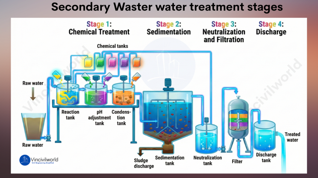
Secondary wastewater treatment uses biological processes to remove dissolved and suspended organic pollutants from sewage. It follows primary treatment and greatly lowers BOD levels. Microorganisms break down waste and improve water quality. This process creates cleaner effluent for discharge or reuse. Secondary treatment of sewage relies on activated sludge systems and trickling filters. These biological wastewater treatment methods work with constant aeration. The wastewater aeration process keeps microorganisms active and effective. Plants use aeration tanks and clarifiers for stable operation. Types of secondary wastewater treatment include activated sludge, oxidation ditches, SBR systems, and trickling filters. Each system supports reliable pollutant removal in municipal and industrial plants. Operators use the secondary treatment process in sewage treatment plants to reduce pathogens and organic matter. Advantages of secondary wastewater treatment include higher efficiency and better environmental protection. Secondary treatment vs tertiary treatment differs by the degree of purification offered.
n this blog, I will walk you through various biological methods used in the secondary treatment of wastewater. Before diving deep into the biological treatment processes, make sure you understand the entire wastewater treatment process. So please go through our blog,
What is Secondary or Biological treatment for wastewater?
Secondary or biological treatment for wastewater uses bacteria to remove dissolved and suspended organic pollutants. These microorganisms consume organic matter as food and convert it into carbon dioxide, water, and energy for growth. This process reduces BOD and improves water quality in the secondary treatment of sewage. It also protects the dissolved oxygen balance in rivers, lakes, and receiving streams. Biological wastewater treatment methods work in controlled environments inside treatment tanks. Operators maintain proper aeration, mixing, and retention time to keep microorganisms active. The wastewater aeration process plays a major role in activated sludge systems and other types of secondary wastewater treatment.
Illustration of the secondary wastewater treatment stages, including chemical treatment, sedimentation, neutralization and filtration, and discharge of treated water.
The Biological treatment or decomposition of organic matter takes place in two ways as shown below:
Anaerobic Wastewater treatment
Aerobic Wastewater treatment
Anaerobic wastewater treatment works without oxygen and produces biogas. Aerobic wastewater treatment uses oxygen and supports faster decomposition. Both methods enhance the secondary treatment process in sewage treatment plants, and moreover, they ensure efficient pollutant removal.
Anaerobic Wastewater Treatment
Anaerobic wastewater treatment uses anaerobic microorganisms to break down and remove organic pollutants from wastewater. The anaerobic wastewater treatment process consists of two major stages:
Acidification
Methane generation
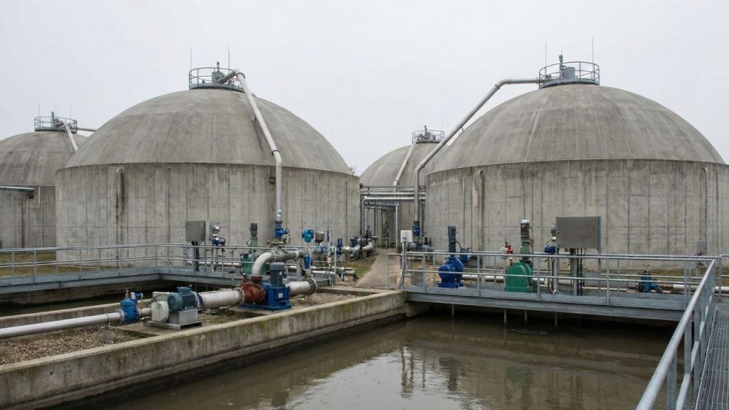
Anaerobic treatment tanks used in secondary wastewater treatment to break down organic matter.
In the initial acid-forming or acidification phase, anaerobes convert complex organic molecules into simpler, short-chain volatile organic acids. The second stage, known as the methane-production phase, includes two key steps:
Acetogenesis
Methanogenesis
During acetogenesis, anaerobes transform organic acids into acetate, hydrogen gas, and carbon dioxide. In the methanogenesis step, microbes react with these products to generate methane gas and carbon dioxide, completing the anaerobic treatment process.
Anaerobic systems are widely used for treating wastewater streams with high organic loads and warm temperatures. They offer several advantages over aerobic or biological wastewater treatment methods, including lower sludge production and the generation of valuable energy-rich by-products.
Aerobic Wastewater Treatment
Aerobic wastewater treatment uses oxygen-dependent microorganisms to break down organic pollutants efficiently. Furthermore, this biological treatment process involves aeration tanks where microbes oxidize waste, producing cleaner effluent. As a result, aerobic wastewater systems offer fast decomposition, stable operation, and high treatment efficiency, making them ideal for municipal and industrial aerobic wastewater treatment processes.
The aerobic wastewater treatment systems use oxygen-feeding microorganisms to clean water. These systems take advantage of the natural microbial decomposition process to break down industrial wastewater pollutants and remove them.
Biochemical Oxygen Demand (BOD) is directly related to aerobic wastewater treatment. It measures the amount of oxygen microorganisms need. This oxygen is necessary to break down organic pollutants.
Biochemical Oxygen Demand
The biochemical oxygen demand (BOD) provides a clear measure of the organic pollutants decomposed by bacteria during wastewater treatment. BOD refers to the amount of dissolved oxygen required by aerobic organisms to break down organic matter into smaller molecules. Additionally, high BOD values indicate a greater concentration of biodegradable material in the wastewater, signaling increased organic pollution levels.
Aerobic digestion is preferred for large quantities of dilute wastewater with BOD₅ < 500 mg/L. It is suitable for most aerobic wastewater treatment systems. For highly polluted wastewater streams with BOD₅ > 1000 mg/L, anaerobic digestion is recommended. It handles stronger organic loads more efficiently.
Types of Secondary or Biological wastewater Treatment Methods
The three most commonly used type of aerobic secondary wastewater treatment procedures for are listed below:
Trickling filter
Oxidation pond
Activated sludge wastewater treatment
Moving Bed Biofilm Reactor (MBBR)
Now, let’s dig deeper into their features and working. Off, we go.
Trickling Filter in Secondary wastewater treatment
A trickling filter is an aerobic secondary wastewater treatment system. It uses a microbial biofilm attached to filter media to break down and remove organic pollutants. This biological wastewater treatment method is called an attached-growth process. In contrast, suspended-growth systems keep microorganisms mixed within the effluent. Trickling filters offer stable performance, effective BOD reduction, and low operational complexity, making them a reliable option in modern secondary wastewater treatment processes.
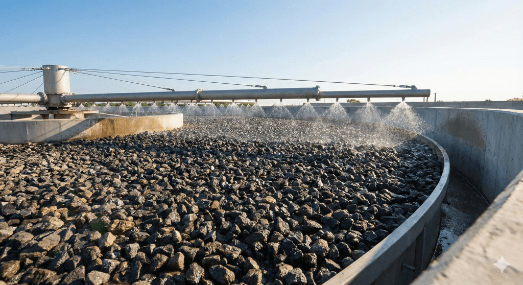
A trickling filter system used in secondary wastewater treatment, showcasing a microbial biofilm attached to filter media for effective organic pollutant removal.
A trickling filter consists of a fixed bed of rocks, coke, gravel, slag, polyurethane foam, sphagnum peat moss, ceramic, or plastic media.
As wastewater trickles down, bacteria attach to the media and form a microbial slime layer (biofilm).
The continuous flow of sewage over the biofilm allows microbes to consume dissolved organic pollutants.
They release carbon dioxide, water, and other oxidised end products as wastewater passes over the media.
This process lowers the sewage’s biochemical oxygen demand (BOD).
Air moving upward through the media crevices supplies oxygen required for aerobic microbial activity.
The biofilm absorbs and adsorbs organic compounds and inorganic ions such as nitrite and nitrate.
The biofilm layer needs dissolved oxygen for effective biological oxidation.
As the biofilm thickens, available oxygen depletes before reaching the lower layers.
Anaerobic conditions develop at the base of the slime layer.
Microbes enter a decay stage and lose their ability to attach.
The biofilm detaches and becomes part of the secondary sludge, a process known as sloughing.
Trickling filters are widely used in milk processing, paper mills, and pharmaceutical wastewater treatment.
Ever heard of a pond which treats wastewater? Let’s look at what’s happening inside such oxidation ponds.
Oxidation Ponds
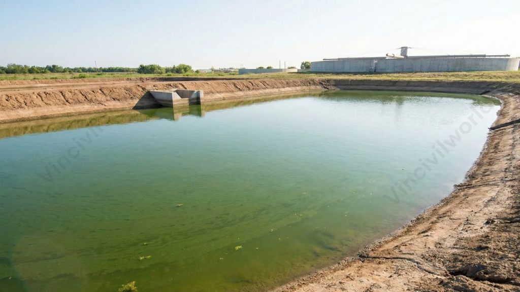
Oxidation ponds are artificial ponds that treat wastewater through the combined action of sunlight, microbes, and oxygen to reduce organic content and pathogens. Moreover, this waste stabilization pond uses microbes to stabilise residential, commercial, and industrial wastes. Typically, it appears as a shallow treatment pond with a water depth of 2–6 feet.
Industrial or domestic wastewater enters the oxidation pond through the inlet system. Bacteria then convert biodegradable organics into inorganic molecules through microbial interaction, producing carbon dioxide. Common bacteria in these stabilisation ponds include Achromobacter, Proteus, Alcaligenes, Pseudomonas, Thiospirillum, and Rhodothecae.
An oxidation pond used for biological wastewater treatment, combining sunlight, microbes, and oxygen to reduce organic content and pathogens.
Anaerobic bacteria first convert insoluble organic waste into soluble organic acids such as ethanol without oxygen. These acids are further decomposed, releasing H₂S, NH₃, CH₄, CO₂, and other gases. Non-biodegradable solids settling at the bottom form sludge.
Most ponds require both bacteria and algae to maximise the breakdown of organic matter and remove contaminants. Algae produce oxygen during photosynthesis and leave an excess amount. Aerobic bacteria use this oxygen for respiration and oxidation of organic matter.
Treated water exits through the pond’s outlet system. Dredging removes accumulated sludge from the pond. Filtration or a combination of chemical treatment and settling removes algal and bacterial biomass.
Now, let’s move on to the various configurations of oxidation ponds.
Oxidation Pond Configurations
Waste stabilization ponds are artificial basins designed for biological wastewater treatment, consisting of single units or multiple series of anaerobic, facultative, or maturation ponds. Moreover, the main oxidation pond configurations used in wastewater treatment are:
A single facultative pond.
An anaerobic pond followed by a facultative pond.
A facultative pond followed by maturation ponds in series.
A series of maturation ponds preceded by an anaerobic pond and a facultative pond.
These configurations help optimise performance in waste stabilization pond systems.
Anaerobic Pond
Anaerobic ponds are deep ponds (usually 3.0 to 5.0 m) that receive raw wastewater. Most of the solid matter in the wastewater settle to the bottom as sludge. Due to the depth of the pond, oxygen can’t penetrate to the bottom of the pond. Thus the sludge digestion takes place under anaerobic conditions.
Facultative Pond
After coming out of an anaerobic pond, the remaining solid particles in the wastewater settles into a larger but shallow pond called a facultative pond. Air and sunlight kill the harmful germs in the wastewater and makes it less dangerous to the aquatic flora and fauna.
Maturation Ponds
Maturation ponds are two or three ponds in series wherein sunlight and oxygen destroy more harmful germs and make the liquid fit enough to be released for irrigation or into a river. Moreover, the higher the number of maturation ponds, the cleaner the effluent becomes.
Activated Sludge wastewater treatment Process
The Activated Sludge wastewater treatment method employs aerobic microorganisms that can digest organic substances in sewage. Also, they have the ability to cluster together via flocculation. The flocculated particles settle out as sludge. As a result, the liquid coming out is relatively free of suspended solids and organic matter.
Overview of an activated sludge wastewater treatment plant, showcasing aeration tanks and clarifiers for effective pollutant removal.
The sludge blanket becomes Return Activated Sludge (RAS) once it has settled. Then, the RAS returns to the primary clarifying tanks, where the bacteria in it aid in the breakdown of organic waste in the entering sewage.
Anaerobic sludge blanket reactors
A popular method used in the anaerobic secondary treatment for water.
The wastewater is carried across a free-floating “blanket” of suspended sludge particles in sludge blanket reactors, which are a type of anaerobic treatment.
Anaerobes in the sludge multiply and accumulate into larger granules that settle to the bottom of the reactor tank and can be recycled for future cycles as they decompose the organic contents in the wastewater.
The treated effluent rises and exits the unit.
Throughout the treatment cycle, collection hoods collect biogases produced by the degradation process.
Secondary wastewater treatment uses biological processes to remove organic pollutants through methods like activated sludge and trickling filters.
Anaerobic and aerobic treatments both improve water quality, with anaerobic processes operating without oxygen and producing biogas.
Trickling filters employ a biofilm of microbes on media to reduce biochemical oxygen demand (BOD) and purify wastewater.
Oxidation ponds rely on sunlight, microbes, and oxygen to treat wastewater, showcasing various configurations for effectiveness.
Activated sludge processes involve aerobic microorganisms that cluster together, aiding in the removal of suspended solids and organic matter.
Conclusion
We explored the key secondary wastewater treatment methods, including the trickling filter system, oxidation pond process, activated sludge process, and anaerobic sludge blanket reactors. Each of these biological wastewater treatment methods plays a crucial role in reducing organic pollutants, lowering BOD levels, and improving overall effluent quality. The sludge produced from these secondary treatment units undergoes dewatering and digestion to reduce volume and enhance stability. Afterward, the dried sludge is commonly used in landfills or converted into nutrient-rich fertilizer, supporting sustainable wastewater treatment and reuse practices. Ultimately, these methods strengthen modern secondary wastewater treatment systems and ensure reliable environmental protection.
That’s it about secondary treatment methods for wastewater. Hope you found it informative.
Primary wastewater treatment is the essential first step in preparing sewage for advanced purification systems. At this crucial stage, operators employ specific primary treatment methods to effectively remove large particles. This vital process prevents potential damage to valuable equipment and avoids obstructing the continuous flow of wastewater. The treatment process initially starts with screening, which extracts substantial debris from the incoming wastewater. Subsequently, grit removal follows, meticulously separating coarse waste, plastics, sand, and various stones. This diligent separation maintains smooth and efficient operation throughout all later treatment units.
After screening and grit removal, the wastewater progresses into settling tanks designed for purification. Within these tanks, the sedimentation process allows heavier solids to gracefully sink, consequently forming what is known as sludge. Simultaneously, lighter oils and greases accumulate on the surface, which are then carefully skimmed off.
By significantly reducing the overall solid load during these early stages, primary treatment demonstrably enhances the performance of all subsequent wastewater treatment stages. This method is notably simple, exceptionally effective, and absolutely crucial for safeguarding both valuable infrastructure and delicate natural water bodies.
Sewage is temporarily stored in a calm basin during primary treatment for wastewater. In this process, heavy materials sink. Oil, grease, and lighter solids float to the top. Wastewater reaching a treatment plant through pipes first undergoes primary treatment irrespective of its source.
In the previous blog, Wastewater Treatment- Stages and Process full details, I had given an overview of the wastewater treatment process. In this blog, we go on a trip with wastewater entering the primary treatment plant. Let’s dive deep into primary treatment for wastewater and closely observe each of the processes.
Primary wastewater treatment process removes large and suspended solids using physical methods . This is to protect downstream units and improve overall treatment efficiency.
Main Stages
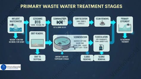
Illustration depicting the stages of primary wastewater treatment, including screening, grit removal, sedimentation, flocculation, and scum removal.
Screening
Grit removal
Sedimentation (Primary clarification)
Flocculation
Sludge removal and handling
Scum removal
Let us dive deep into each of the primary waste water treatment stages .
Screening – Primary Treatment for Wastewater
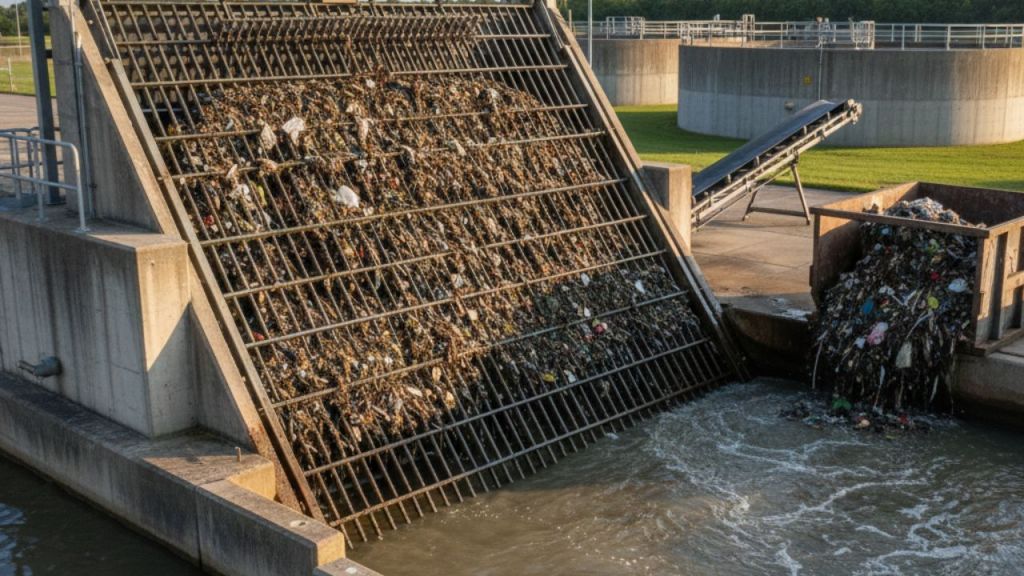
The first step in the primary wastewater treatment process is screening. This stage plays a major role in removing large solids before advanced treatment begins. In primary treatment for wastewater, the screening system blocks stones, rocks, and plastics. It even prevents dead animals from entering the treatment plant. These materials can damage pumps and obstruct the flow in pipelines. Therefore, eliminating solid waste at the initial stage makes all later wastewater treatment stages more efficient.
A screening system in primary wastewater treatment captures and removes large debris before the purification process.
Screens and settling units remove most floating and large materials from the wastewater. The flow passes through screening and grit removal wastewater equipment such as bar screens. These screens consist of parallel metal bars, wires, or gratings placed at a 30°–60° angle to the flow. Based on the cleaning system, screens can be manually cleaned or mechanically cleaned. In manually cleaned racks, the opening size ranges from 25–50 mm. For mechanically cleaned screens, the opening size ranges from 5–40 mm.
Based on the size of the screen opening, we have 3 types of screens as follows:
Coarse screens (≥ 50 mm)
Medium screens (25-50 mm)
Fine screens (10-25 mm).
Normally, domestic wastewater treatment uses medium screens. The channel approach velocities fall in the range of 0.3 to 0.6 m/s for manually cleaned racks and from 0.6 to 1.0 m/s for mechanically cleaned racks.
The wastewater moves to comminutors after screening.
Comminutors
Comminutors reduce bigger suspended particles to smaller sizes by cutting and grinding action. Large plants frequently employ comminutors. It consists of a fixed screen that has either a rotating or oscillating cutter. Alternatively, there is a curved screen with a rotating or oscillating cutter. They are of considerable importance in treatment plants located in cold areas since they eliminate the trapping of waste on freezing screens.
Next, we are going to see grit chambers and their functions.
Grit Chambers
Aerated grit chambers in primary wastewater treatment remove sand, gravel, and heavy particles using controlled aeration. This process protects pumps and improve the treatment efficiency.
The wastewater after screening enters a grit chamber to settle the grit particles like sand, pebbles etc.
Grit chambers are long and narrow tanks. They reduce the flow of water. This allows particles like sand, stones, and eggshells to settle out.
They are highly relevant in places with combined sewer systems. These systems carry a significant amount of silt, sand, and gravel washed off roadways or land during a storm.
They protect pumps and pipelines from abrasion and prevents the deposition of grit in pipes and channels.
Types of Grit chambers
Types of grit chambers in primary wastewater treatment help remove heavy particles and protect downstream equipment efficiently.
There are two common types of grit chambers – Horizontal flow and Aerated.
Horizontal Flow Grit chambers permit a velocity of about 0.3 m/s to settle the grit material while allowing the organic impurities to flow through the chamber.
The aerated grit chamber constitutes a spiral flow aeration tank. Wastewater takes a spiral path through the aeration tank. This spiralling action throws away the grit particles into a hopper located underneath.
Scrappers remove the grit for disposal.
Aerial view of wastewater treatment facility, showcasing the sedimentation tanks where solids settle during primary treatment.
Flow Equalisation – Primary treatment for waste water
Under uniform flow rates, clarifiers and mechanised secondary treatment are more efficient.
Equalization basins store diurnal or wet-weather flow peaks temporarily and make the water flow rate uniform.
Basins serve as a temporary holding area for the incoming wastewater during temporary plant shut down and maintenance.
It acts as a means of diluting and distributing hazardous or high-strength waste into batches.
Flow equalisation basins require variable discharge control which features bypass and cleaning options as well.
Cleaning is easier if the basin is downstream of screening and grit removal.
The wastewater, then moves to sedimentation ponds, settling tanks, or clarifiers after the removal of settled grit. The sedimentation process removes the settleable solids by gravitational settling under quiescent conditions.
On proper adjustment of water flow in the sedimentation tank, the suspended particles begin to fall to the bottom and form a solid mass. Raw primary biosolids, also known as sludge, is the solid mass formed out of the particles. This sludge is removed by vacuum suction or raking it to a discharge point.
Types of Primary Sedimentation Tanks
Rectangular Horizontal Flow Tank
Circular Radial Flow Tank
Up Flow Tanks
Rectangular Horizontal Flow Tank
Feed enters at one end along the width of the horizontal tank.
They can be economically built side-by-side with common walls.
Length ranges from15 to 100m and width ranges from 3 to 24m (length/ width ratio 3:1 to 5:1).
In rectangular tanks, the flow occurs in a horizontal, lengthwise direction.
Rectangular tanks, sometimes use baffle walls to prevent short-circuiting.
Rectangular sedimentation tanks provide reduced maintenance expenses.
Circular Radial Flow Tank
In circular radial flow tanks, influent is fed through a central pipe of the tank and radial flow happens.
They have diameters ranging from 3 to 60 metres (side water depth range from 3 to 5m).
Mechanical sludge scrapers gather the sludge, and a sludge pipe transports it to the bottom.
Circular tanks are more expensive than rectangular tanks, but they have a higher clarification efficiency.
View of primary wastewater treatment tanks, showcasing the sedimentation process essential for removing large particles and preparing sewage for advanced purification.
Up Flow Tanks
Up Flow tanks find application in small treatment plants.
Feed enters through openings along the bottom side of the tank and the effluent after clarification collects at the top.
The flow takes place in a vertical direction.
A sludge blanket in the lower part of the tank acts as a filter for small particles.
The next stage is flocculation which removes the remaining suspended solids.
Flocculation
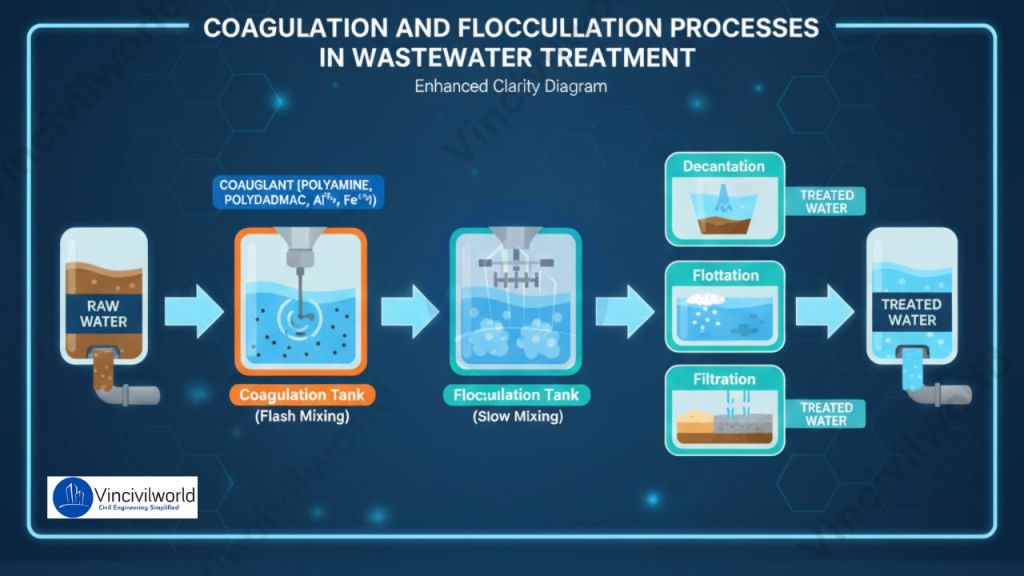
Flocculation is a water treatment process to remove small suspended solids which don’t settle in the sedimentation tank. In this process solids form larger clusters, or flocs on the addition of a flocculent like aluminium sulphate.
The coagulant molecules have a positive charge. Hence, they can neutralize the negatively charged solid particles that are suspended in the water. Neutralization of the particles initiates the flocculation process. The individual suspended particles come together to join and form a larger mass called a floc.
Illustration of the coagulation and flocculation processes in wastewater treatment, showcasing the stages from raw water to treated water.
At the onset of flocculation, we add a chemical polymer. It acts as a bridge between micro and macro flocculants, increasing the mass of particles aggregating together. It also bonds the accumulated material together, preventing it from dissolving even when the water is stirred slightly. After the flocculation, the solid masses are removed either through settling or through the use of filters.
Sludge Removal
In the sedimentation tanks, sludge (the organic component of the sewage) settles out of the wastewater. Mechanical scrapers in the tank’s base continuously move accumulated sludge to a hopper, where it is pumped to sludge treatment facilities. The thickening step removes some of the water before processing the sludge in digesters.
Lighter materials rise to the surface as sludge settles to the bottom of the sedimentation tanks. The constituents of ‘scum’ are grease, oils, plastics, and soap. Scum is skimmed off the surface of the wastewater by slow-moving rakes. Scum is thickened before being poured into the digesters with the sludge.
Primary treatment removes about 60% of the total suspended solids and nearly 35% of BOD. It doesn’t remove the dissolved impurities. The waste must undergo secondary treatment in order to be completely free of toxic substances.
That’s it about primary treatment for wastewater. But, our trip doesn’t end here. Next, we move on to the secondary wastewater treatment plant – Secondary Treatment for Wastewater – Methods and Process. So, how was the trip? Let us know in the comment
Primary Treatment for Wastewater is the first crucial step in treating sewage, removing large particles to protect equipment.
It involves screening, where coarse waste is separated, followed by grit removal and sedimentation processes.
Sedimentation allows heavier solids to settle, forming sludge, while oils and greases float to be skimmed off.
The process removes about 60% of total suspended solids and 35% of biochemical oxygen demand, but not dissolved impurities.
Following primary treatment, wastewater must undergo secondary treatment for complete purification.
Conclusion
Primary treatment for wastewater plays an essential role in protecting both treatment facilities and the environment. It removes large solids, sand, grit, oil, and floating debris before advanced purification begins. Processes like screening, grit removal, sedimentation, and flocculation work together to reduce the pollutant load effectively. By eliminating harmful materials early, primary treatment improves the efficiency and lifespan of pumps, pipelines, and biological treatment units. It also ensures that downstream processes receive cleaner wastewater, leading to better final effluent quality. Although simple and cost-effective, primary treatment remains the foundation of a reliable wastewater treatment system. Therefore, investing in and maintaining strong primary treatment operations is crucial for sustainable water management and public health protection.
What is Sewage? Sewage is the wastewater produced from homes, industries, commercial areas, and even stormwater entering the drainage network. It contains human waste, food residues, soaps, and chemicals. It also includes oils and harmful microorganisms. These substances can pollute the environment if not treated properly. By identifying the types and sources of sewage, we can classify it into domestic sewage and industrial sewage. Each has different contamination levels. To protect public health, the sewage treatment process removes pollutants. It utilizes physical, biological, and sometimes advanced treatment methods. During treatment, key sewage quality indicators such as BOD, COD, TSS, and pH are monitored. Monitoring also includes coliform bacteria to ensure standards are met. This article explains the meaning of sewage. It discusses where sewage comes from and how it is treated. Additionally, it covers how sewage quality is evaluated for safe disposal or reuse.
lobally, 44% of sewage is not safely treated, according to UN-Water 2021. Releasing untreated sewage into water bodies pose a great threat to humans as well as the environment. But, how do we understand the quality and the number of pollutants in it? This blog let me walk you through the basics of sewage, its sources, types, and quality indicators.
Here are a few shocking facts about water pollution. These facts highlight its effects before we delve into the details about sewage. Water Pollution – Effects and Causes. Going through this blog will help you better understand the importance of treating sewage.
Sewage is a type of industrial and domestic wastewater that enters the sewerage system from household bathrooms, toilets, kitchens, laundries and drains. It consists of approximately 99.6% water and 0.4% of biodegradable pollutants and small solid particles. A sewage treatment plant considers the following parameters of sewage:
The rate of flow
Physical state
Chemical and hazardous contents
Bacteriologic status are all factors to consider (which organisms it contains and in what quantities).
Components of Sewage
The major components of sewage include:
Greywater – wastewater from sinks, bathtubs, showers, dishwashers, and clothes washers
Blackwater – wastewater from toilets, mixed with the human waste flushed away
Sewage is generated from several daily domestic and industrial activities. To understand its characteristics and treatment needs, sewage is commonly classified into different Types of Sewage based on its origin. The major sources include:
Domestic Sewage (Household Wastewater)
Domestic sewage is discharged from kitchens, toilets, and washing activities, containing:
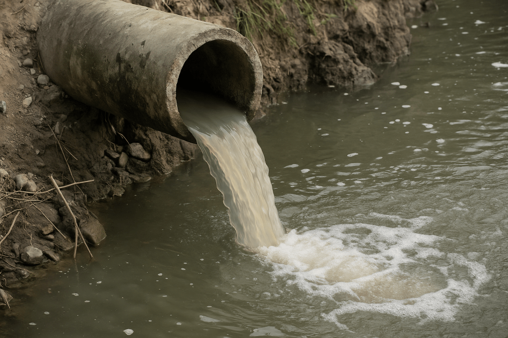
Sewage flowing from a drainage pipe into a water body, highlighting the importance of proper wastewater treatment.
Human excreta: faeces, urine, blood, sanitary waste
Bathing and personal hygiene water
Dishwashing, laundry, and floor-cleaning water
Household liquids such as cooking oil, detergents, paints, lubricants, and pesticides
Industrial Sewage
Industrial sewage is mainly wastewater from factories and processing units, containing chemicals, dyes, oils, acids, and heavy metals.
Stormwater / Urban Runoff
Rainwater flowing from:
Roads, railways, parking lots, pavements
Roofs, gardens, fuel stations Carrying oil spills, food waste, tyre rubber residue, metals, pesticides, and litter.
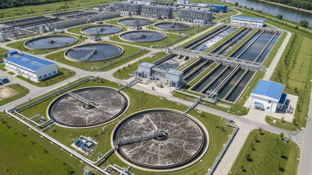
An aerial view of a sewage treatment plant showcasing multiple processing tanks and facilities for wastewater management.
A clear understanding of these types of sewage sources helps engineers design the right sewage treatment process and improve public health and environmental protection.
Sewage Quality Indicators
Sewage quality indicators are laboratory tests that determine if wastewater is suitable for disposal, treatment, or reuse. These tests measure the physical, chemical, and biological characteristics of sewage. Physical characteristics don’t demand complex procedures since our physical senses alone can detect them. Bioassays and aquatic toxicity tests determine the biological properties while titrations and related laboratory procedures give the chemical characteristics.
Physical Characteristics
The physical characteristics can be detected using our senses such as sight, smell, and touch.
1️⃣ Temperature
The temperature of sewage indicates the level of contamination. It varies depending on biological and chemical reactions in the sewer or treatment plant. When sewage becomes septic, microbial activity increases the temperature. A drop in temperature can indicate groundwater infiltration.
2️⃣ Colour
Colour indicates the age and condition of wastewater. Fresh one appears light brownish-grey. Under anaerobic conditions, oxidation of organic matter turns the sewage from grey to dark grey or black. Black colour signals septic one.
3️⃣ Odour
Fresh sewage has a mild oily smell. Septic one produces a foul odour due to hydrogen sulphide (H₂S) formed under anaerobic decomposition. Industrial wastewater may contribute additional odorous compounds. Odour measuring devices include:
H₂S meter
Olfactometer
Scentometer
Butanol wheel
4️⃣ Turbidity
Turbidity measures the ability of sewage to transmit light. Suspended and colloidal particles scatter or absorb light, increasing turbidity. High turbidity indicates poor wastewater quality and the presence of solids.
Measure of light-transmitting property of water.
Turbidity measurement involves comparing light scattered by sample to that by a reference suspension under same conditions.
Colloidal matter absorb light and thus prevent transmission.
Thus, if a sample doesn’t transmit light, it indicates that the sample is turbid due to presence of suspended and colloidal substances.
5️⃣ Solids
Solids are the residues left after evaporation and drying at 103.2°C. They include:
Solids are those substances that remain as residue after evaporation and drying at 103.20C. Suspended particles are solids that have not dissolved in wastewater. Floatable solids or scum are suspended materials that float.
Settled solids, often known as grit or sludge, are suspended materials that settle. Settleable solids refer to the solids that settle at the bottom of an Imhoff cone after the water has settled for one hour. It is a measure of the quantity of sludge that can settle by primary sedimentation.
A close-up view of wastewater exhibiting bubbles, highlighting the presence of organic solids and pollutants.
Volatile solids are solids that burn or evaporate at temperatures between 500°C and 600°C. In a wastewater treatment plant, the sediments provide food for bacteria and other living organisms and thereby they decompose the waste. The majority of organic substances included in municipal garbage come from living plants and animals.
Organic solids serve as food for bacteria during treatment and support biodegradation.
Chemical Characteristics
Sewage comprises both organic and inorganic compounds and numerous gases produced by decomposition, such as H2S, CO2, CH4, and NH3. pH, DO (dissolved oxygen), oxygen demand, nutrients, and hazardous compounds are chemical features of wastewater that are of particular interest.
1️⃣pH
The pH scale describes the acidity or alkalinity of aqueous solutions. Initially, the sewage has high pH. Further, the pH drops when it gets septic, and then rises again as it goes through the treatment process.
2️⃣Dissolved Oxygen (DO)
The term “aerobic” or “fresh” refers to wastewater that contains DO. At 1.0 atm pressure, oxygen solubility in freshwater ranges from 14.6 mg/L at 0oC to roughly 7 mg/L at 35oC.
3️⃣Biochemical Oxygen Demand (BOD)
BOD is the amount of oxygen needed for aerobic bacteria to decompose organic matter. This process occurs over 5 days at a typical temperature of 20oC. We have a blog, Biochemical Oxygen Demand || Dissolved Oxygen of Water || Full Details. It covers all the topics that one should know about BOD. Don’t forget to check it out.
4️⃣Chemical Oxygen Demand (COD)
Laboratory analysts determine Chemical Oxygen Demand (COD) by oxidizing the organic matter in a wastewater sample. They use a strong chemical oxidant for this process. The COD value represents the oxygen equivalent of all organic compounds in the sample. These compounds are susceptible to chemical oxidation. The value indicates how much oxygen would be required to break them down.
Bacteria, viruses, and parasites are the three biological entities found in wastewater.
Bacteria
The typical concentration of bacteria in raw sewage ranges from 500,000 to 5,000,000 per mL. These bacteria use external and intracellular enzymes. They break down complicated molecules into stable chemicals. Bacteria can be classified into three types depending on their manner of action:
Aerobic Bacteria
Anaerobic Bacteria
Facultative Bacteria
Along with bacteria, it also contains viruses, helminths, parasites etc.
Sewage is wastewater from homes and industries, containing pollutants that can harm the environment if untreated.
It mainly categories into domestic and industrial sewage, each with different contamination levels.
Sewage quality indicators, such as BOD, COD, and pH, help evaluate its treatment needs and safety for disposal or reuse.
Globally, 44% of sewage isn’t safely treated, creating significant health and environmental risks.
Understanding sewage’s components and sources is essential for effective treatment and protecting public health.
Conclusion
Understanding What is Sewage ? is essential for effective environmental and public health protection. Sewage originates from many sources of sewage, mainly domestic and industrial sewage, and can contain harmful pollutants. By analyzing sewage quality indicators such as BOD, COD, TSS, pH, and coliform bacteria, engineers can assess pollution levels accurately. A well-designed sewage treatment process ensures the safe disposal or reuse of wastewater by removing physical, chemical, and biological contaminants. Proper wastewater treatment and pollution control techniques help maintain clean water bodies, prevent disease outbreaks, and support sustainable urban development. Continuous monitoring and advancements in treatment technologies remain crucial for improving sewage management and protecting our environment for future generations.