A retaining wall is a structure designed to hold or support soil behind it. These walls are commonly used in landscaping, construction, road development, and residential properties where uneven ground levels need additional support. A retaining wall helps reduce soil movement, erosion, and pressure caused by sloped terrain while also improving the usability of outdoor spaces.
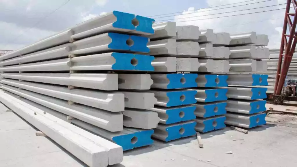
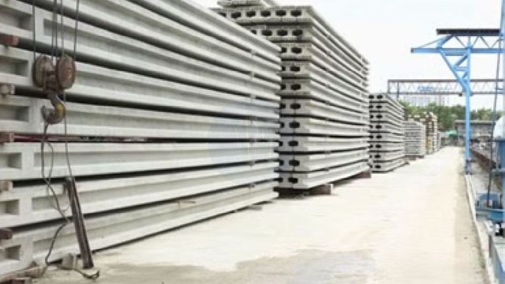
Retaining walls can be built using materials such as concrete, stone, brick, timber, or reinforced blocks. The type of wall used often depends on soil conditions, drainage requirements, wall height, and the overall purpose of the project. In both residential and commercial construction, retaining walls play an important role in long-term ground stability and site management.
- Understanding Retaining Wall in Construction
- What Is The Purpose Of A Retaining Wall?
- Functions And Advantages
- Types Of Retaining Walls
- Size Of Retaining Wall
- Retaining Wall Installation Costs
- Maintenance And Long-Term Durability
- Common Problems
- Finding Professionals For Retaining Wall Projects
- Wrapping Up
Understanding Retaining Wall in Construction
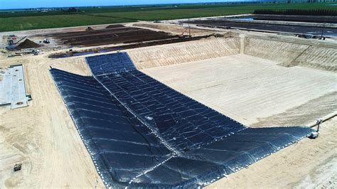
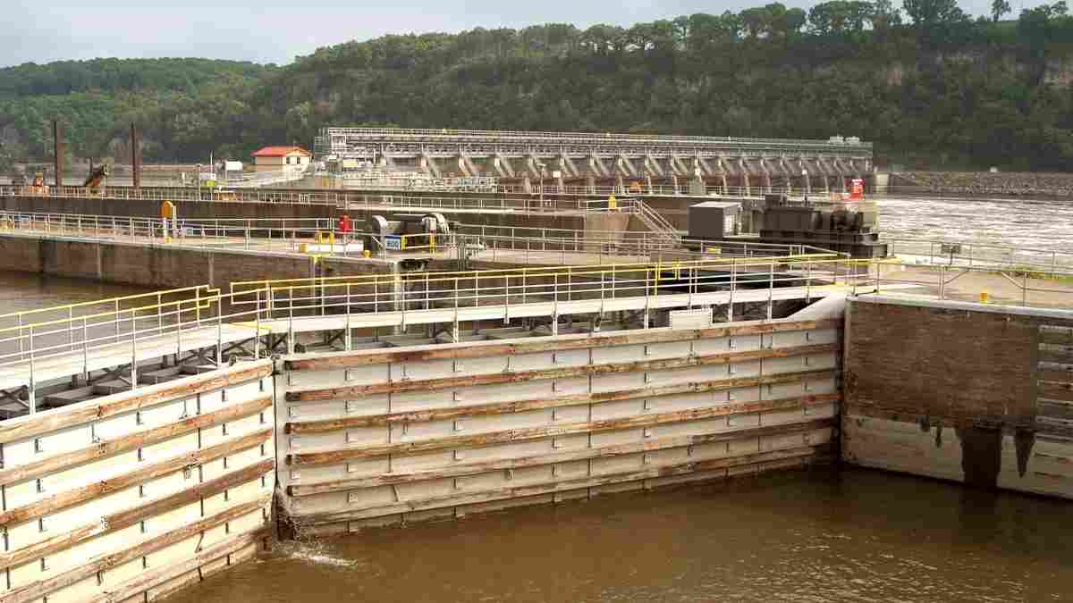
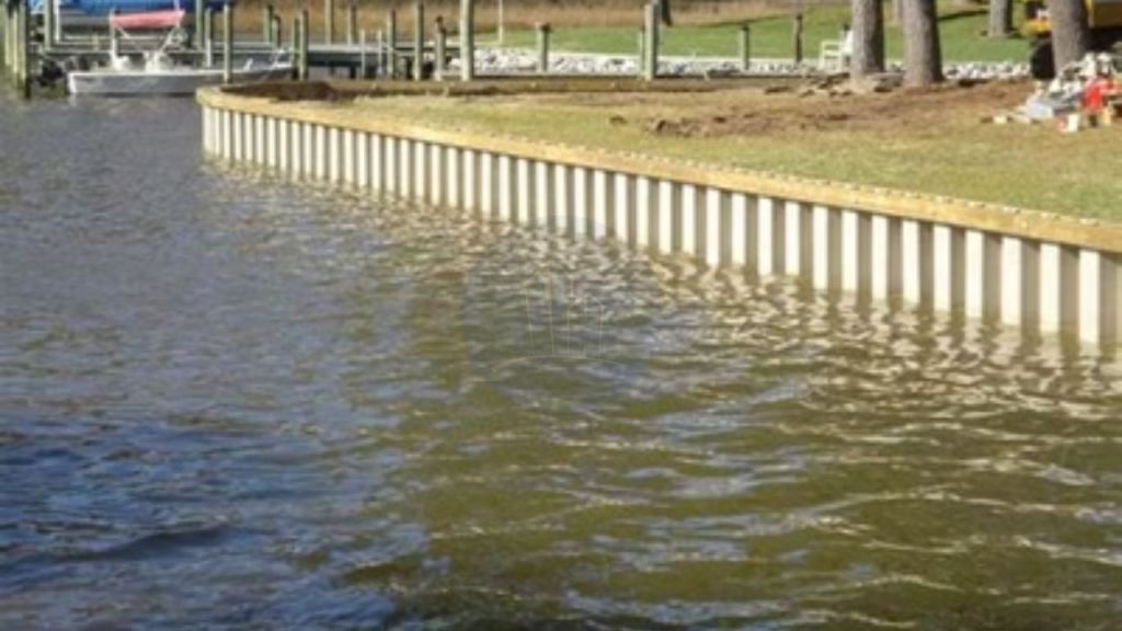
In construction, a retaining wall is designed to resist the lateral pressure created by soil, water, or sloped ground surfaces. These structures are commonly installed where natural slopes may create instability or where flat usable land is needed for building or landscaping purposes.
Retaining walls are often found near gardens, driveways, roads, basements, and hillside properties. In residential landscaping projects, they are also frequently combined with features such as patios, pathways, and outdoor fireplace areas to create more functional outdoor living spaces across various types of terrain.
What Is The Purpose Of A Retaining Wall?
The primary purpose of a retaining wall is to hold back soil and prevent erosion. Without proper support, sloped land can gradually shift over time, especially during periods of heavy rain or changing weather conditions.
Retaining walls also help improve land organization and outdoor functionality. Many residential properties use retaining walls to create level garden spaces, pathways, seating areas, or separated landscape sections across uneven terrain.
Functions And Advantages
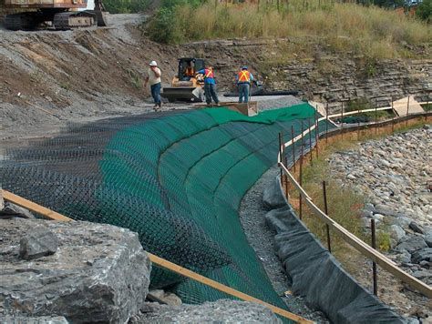
Retaining walls provide both structural and visual benefits within construction projects. Structurally, they help stabilize slopes and reduce the risk of soil movement around buildings or outdoor spaces. This added support can help protect foundations, roads, and landscaping from erosion damage over time.
Beyond structural performance, retaining walls are also used to improve outdoor design layouts. Landscaped properties often combine retaining walls with patios, seating areas, or outdoor fireplace installations to create more functional outdoor living environments while managing elevation changes effectively.
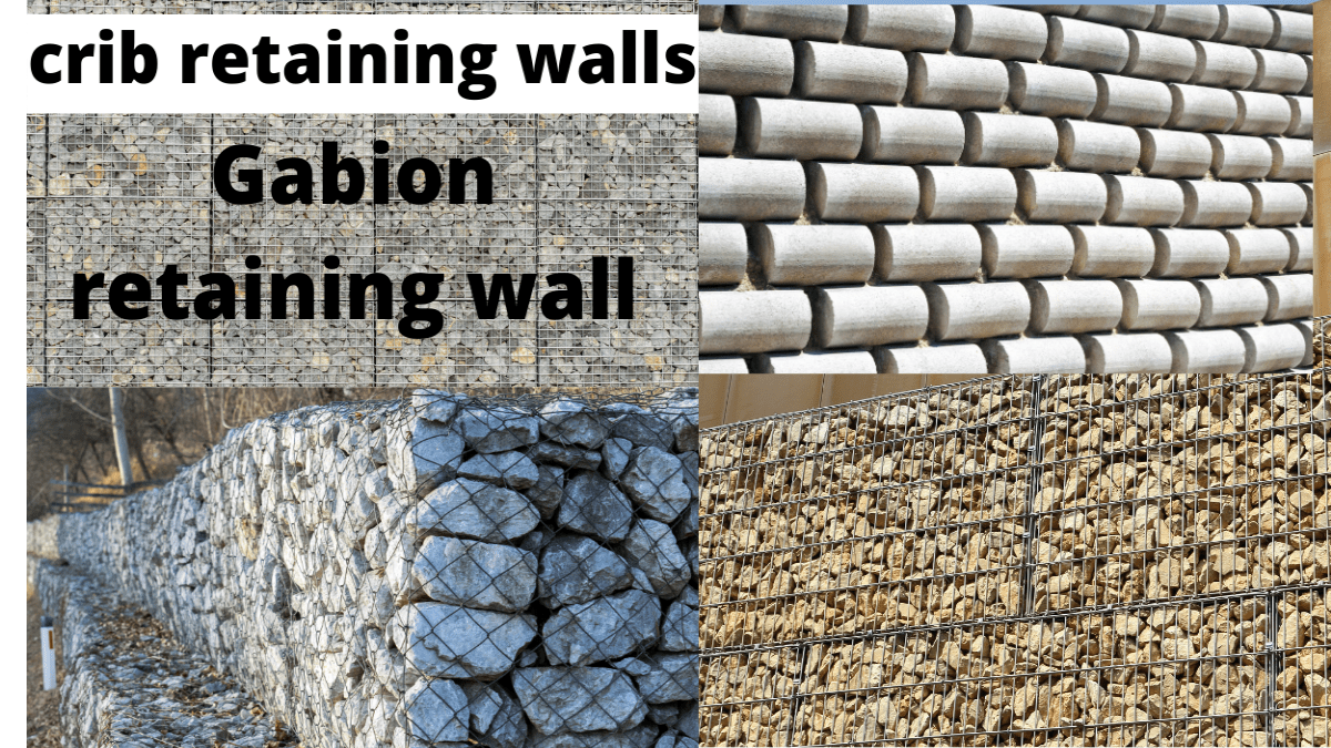
Types Of Retaining Walls
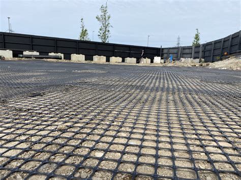
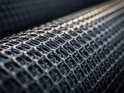
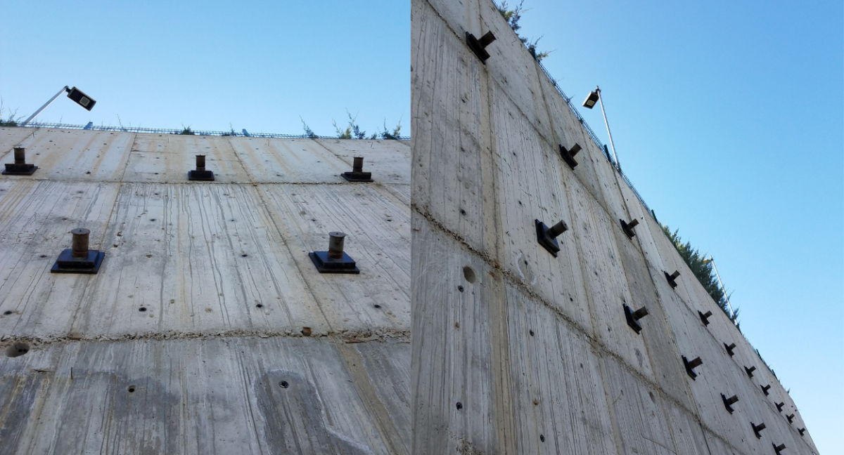
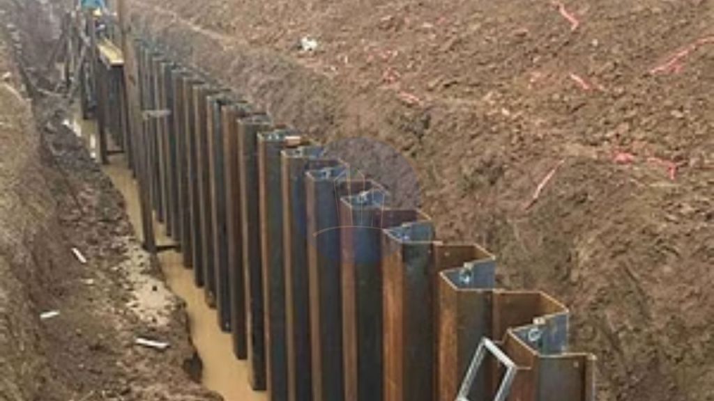
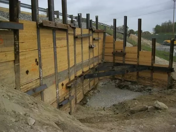
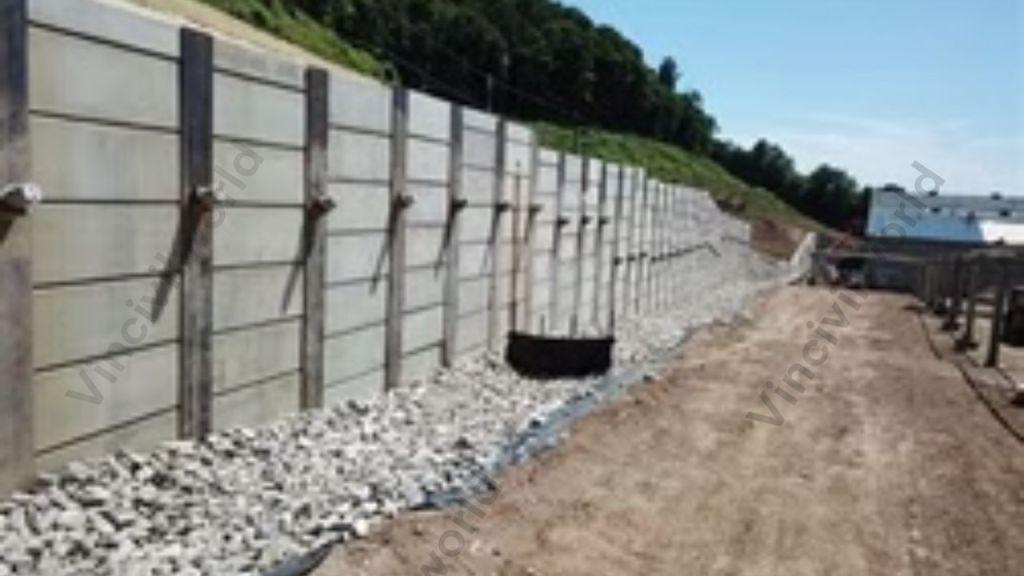
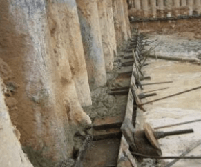
Several types of retaining walls are used depending on the project size, soil conditions, and engineering requirements. Gravity retaining walls rely on their own weight to resist soil pressure, while reinforced retaining walls use steel reinforcement or concrete systems for additional strength.
Cantilever retaining walls are commonly used in larger construction projects because they distribute pressure more efficiently. Segmental retaining walls, often built using interlocking blocks, are frequently used in residential landscaping because of their flexibility and simplified installation process.
Size Of Retaining Wall
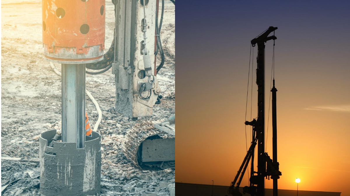
The size and thickness of a retaining wall depend on factors such as wall height, soil type, drainage conditions, and the amount of pressure behind the structure. Smaller garden retaining walls may only require limited reinforcement, while taller walls often need engineering calculations and stronger foundation systems.
Local building regulations may also affect wall dimensions and permit requirements. In many areas, retaining walls above a certain height require professional design approval before construction begins.
Retaining Wall Installation Costs
The cost of building a retaining wall depends on factors such as wall height, materials, drainage systems, and site conditions. Because every project has different structural and landscaping requirements, retaining wall cost estimates can vary significantly between residential and commercial properties.
In the United States, an installation project commonly ranges between around $20 to $75 per square foot depending on the material and wall design. In Canada, pricing is often slightly higher because of labor costs and seasonal construction conditions, with many residential retaining wall projects averaging around CAD $25 to CAD $65 per square foot depending on complexity and materials used.
Factors That Affect Retaining Wall Cost
Retaining wall pricing can vary significantly between projects because costs usually depend on multiple site evaluations and planning considerations before construction begins.
- Wall height and overall size
- Type of material used
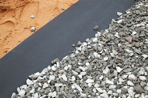
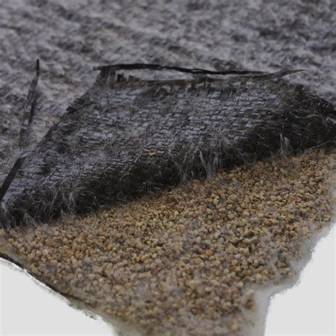
- Soil conditions and drainage requirements
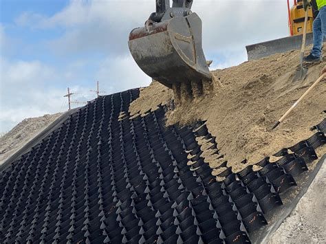
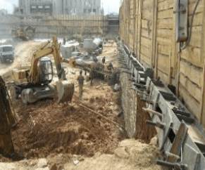
- Excavation and foundation preparation
- Accessibility of the construction site
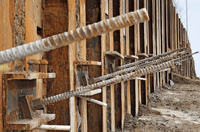
- Reinforcement or engineering requirements
- Local labor and permit costs
- Decorative finishes or landscaping integration
Maintenance And Long-Term Durability
Although retaining walls are built for long-term use, periodic maintenance remains important. Drainage outlets should remain clear, and visible cracks or movement should be inspected before structural issues become more serious.
Environmental exposure, soil pressure, and water buildup can gradually affect wall performance if maintenance is neglected. Proper installation combined with regular inspections generally improves the lifespan of retaining wall systems.
Common Problems
Several issues can affect retaining wall performance over time. Poor drainage is one of the most common causes of wall failure because trapped water increases pressure behind the structure.
Other problems may include weak foundations, insufficient reinforcement, soil erosion, or improper installation techniques. Identifying these issues early can help reduce repair costs and prevent larger structural damage later.
Finding Professionals For Retaining Wall Projects
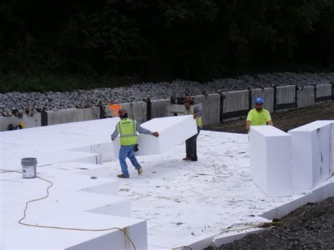
Building a retaining wall often involves more than simply stacking materials together. Soil conditions, drainage systems, wall height, reinforcement, and local regulations can all influence the overall structural performance of the project. Because of this, many property owners choose to work with experienced contractors or landscape professionals when planning larger retaining wall installations.
Professional’s advice from these contractors can also help homeowners better understand a number of considerations before construction begins. Material selection, excavation requirements, drainage systems, and site accessibility are some of the factors that may affect the overall budget depending on the size and complexity of the project.
Wrapping Up
A retaining wall serves an important role in supporting soil, managing elevation changes, and improving outdoor functionality across residential and commercial properties. Different retaining wall systems are designed to handle varying structural conditions depending on wall height, soil pressure, and environmental exposure.
From erosion control to landscape organization, retaining walls provide both practical and visual benefits when installed correctly. Proper planning, drainage, reinforcement, and material selection all contribute to the long-term durability and effectiveness of retaining wall construction projects.