Vee Bee Consistometer Test is a reliable laboratory method used to evaluate the workability of concrete, especially for stiff and low-workability mixes where slump test results are not accurate. The Vee Bee Consistometer test for workability of concrete measures the time required for concrete to remould under vibration, providing a clear indication of consistency. In the workability of concrete Vee Bee test, vibration energy replaces gravity-based flow, making it suitable for dry mixes. Understanding the Vee Bee test procedure helps engineers achieve consistent and repeatable results. The Vee Bee Consistency test of concrete is widely used in laboratories and quality control setups and is considered one of the most dependable tests for workability of concrete for controlled assessment of stiff concrete mixes.
This article explains the Vee Bee Consistometer test, its principle, procedure, applications, and importance in accurately assessing the workability of stiff concrete mixes.
Significance of Quality tests on concrete
Quality tests on concrete are essential for ensuring strength, durability, and performance in construction. These tests help engineers assess the workability of fresh concrete and the quality of hardened concrete. Common quality tests on concrete include checks during the production stage (on fresh concrete before placing), tests on hardened concrete specimens, and evaluations performed directly on finished structures. Including tests like the flow table test for concrete ensures reliable results and consistent quality throughout a project.

Quality tests performed on concrete are classified into
- Production stage quality tests ( On fresh concrete before placing)
- Hardened stage quality tests ( hardened concrete specimens)
- Non Destructive tests On structures ( tests done on the structures )
Also read : Aggregate Crushing test – Strength of aggregate
Also read : 9 lab tests of Bitumen for flexible pavements
Production stage quality tests on fresh concrete
Production stage quality tests on fresh concrete are crucial for ensuring the right workability and consistency before placement. These tests help engineers select the best mix for construction and maintain quality control. Key tests include the slump test, compaction factor test, Vee-Bee test, Kelly ball test, and the flow table test for concrete.
- Slump test
- Compaction Factor test
- Vee- Bee Test
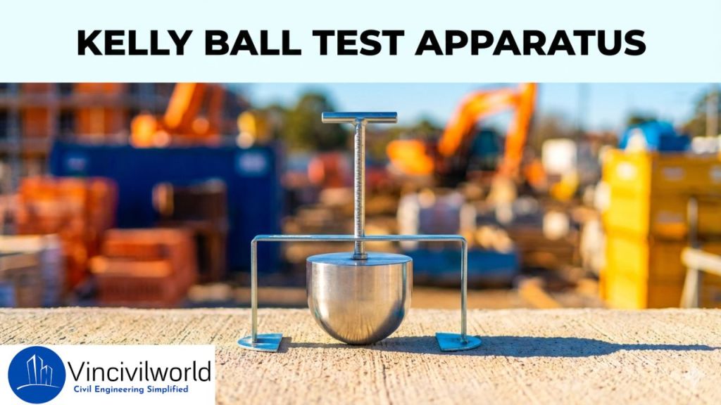
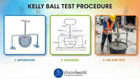
- Kelly ball test
- Flow table test
This article focuses on the Vee Bee Consistometer test, explaining its procedure, importance, and how it compares with other workability tests like the slump test and compaction factor test.
Vee Bee Consistometer test for workability of concrete
The Vee Bee Consistometer Test is a laboratory test used to determine the workability of concrete, particularly stiff and low-workability mixes. It measures the time required for fresh concrete to remould from a conical shape into a cylindrical shape under controlled vibration. This time, known as the Vee Bee time, indicates concrete consistency. Unlike the slump test, the Vee Bee Consistometer test for workability of concrete is suitable for dry mixes that do not flow easily. Commonly used in quality control, this test helps engineers compare mix designs and ensure uniform concrete performance.
Relevant Codes and Standards for Vee Bee Consistometer Test
- IS 1199 (Part 2): 2018 – Methods of Sampling and Analysis of Concrete – Workability
Issued by Bureau of Indian Standards.
This standard covers the Vee Bee Consistometer test, along with slump and compaction factor tests. - BS EN 12350-3 – Testing Fresh Concrete – Vebe Test
Issued by British Standards Institution.
Widely used in the UK and Europe for stiff concrete workability assessment. - DIN 1048 (Part 1) – Testing Concrete – Fresh Concrete Tests
Issued by DIN.
Includes the Vebe test for consistency measurement.
Note: These standards ensure uniform testing procedures, repeatable results, and reliable evaluation of low-workability concrete mixes.Relevant IS code
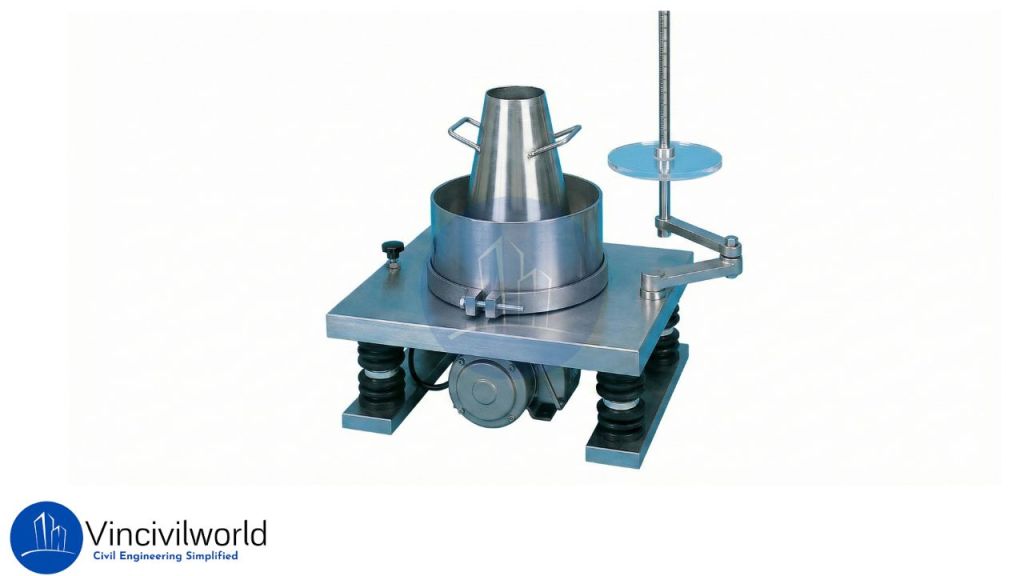
Apparatus used for Vee Bee Consistometer

The Vee – Bee Consistometer includes of
- A vibrator table resting upon elastic supports
- A metal pot
- A sheet metal cone, open at both ends
- A standard iron rod
The dimension of the vibrating table is 380 mm in length, 260 mm in width and height of 305 mm. Also, supporting the table there is a rubber shock absorber. Under the table, there is a vibrator that vibrates electrically. The dimension of the metal slump cone is 300mm height, 200 mm top diameter and 100 mm bottom diameter.
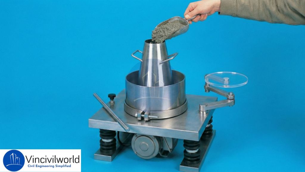
Test procedure
- Initially fill the slump cone with four layers of concrete. Each layer should have a height of one – fourth of the cone.
- After that tamp each layer 25 times using a standard tamping rod and strike uniformly.
- Then after placing the final layer, remove the excess concrete on the top of the concrete.
- Move and place the swivel arm attached to the glass disc on the top of the cone.
- Now remove the cylindrical cone gradually in the vertical direction and note down the slump.
- Then switch on the electrical vibrator and allow the concrete to spread.
- The time taken by the concrete to spread uniformly is noted using the stop clock.
- This time is expressed in vee bee seconds.
The time for the concrete to remould is the Vee-Bee seconds. The Vee Bee consistometer is an indirect measure of concrete workability. This method is suitable for concrete whose slump value cannot be determined. ie, for dry mixes. We can get direct result through this method.
Also Read : Soundness test on aggregate
Key Takeaways
- The Vee Bee Consistometer Test is designed to assess the workability of stiff concrete mixes.
- It measures the time required for concrete to remould under vibration.
- Longer Vee Bee time indicates lower workability of concrete.
- The test provides more reliable results than slump test for dry mixes.
- It is commonly used in laboratory-controlled environments.
- The method helps compare different concrete mix designs.
- Proper vibration is essential for accurate results.
- The test minimizes subjective judgment during workability assessment.
- It is standardized under Indian and international codes.
- The test is an important part of quality control procedures.
- It complements other tests for workability of concrete.
- It ensures consistency during concrete production.
Conclusion
The Vee Bee Consistometer Test plays a crucial role in evaluating the workability of concrete, especially for mixes with low water content. By measuring the remoulding time under vibration, the test provides a clear and quantitative indication of concrete consistency. Unlike the slump test, it performs well for stiff mixes where flow is minimal. When conducted according to standard procedures, the test helps engineers maintain uniformity in concrete production and placement. It also supports effective quality control by enabling comparison of different mix proportions. As one of the reliable laboratory-based tests for workability of concrete, the Vee Bee Consistometer Test remains essential for achieving durable and well-performing concrete structures.