All posts by Vinod Gopinath

Dog legged Staircase – Design, Features and Advantages

A dog-legged staircase is the simplest, common, space-saving, and economical staircase type used in commercial, industrial and residential buildings. A dog-legged staircase consists of two flights running in opposite directions and parallel to each other. They are separated categorically by a landing when the flights change direction.

A dog legged staircase is a space-efficient design consisting of two straight flights of stairs connected by a 180-degree turn. This layout allows the staircase to make a sharp turn without needing extra space for landings. Dog leg stairs are commonly used in residential and commercial buildings where space-saving is crucial. The dog legged stair design minimizes footprint while maintaining functionality and aesthetics. They offer a compact solution for multi-story structures, making them ideal for homes, offices, and small commercial spaces. The dog leg staircase is popular for its simple, practical, and versatile design.

This article is about the features of Dog legged staircase and its design, advantages, disadvantages, and applications.

  1. What is a staircase?
  2. What is a Dog legged staircase ?
  3. Major components of a Dog legged staircase
    1. Thread
    2. Rise
    3. Step
    4. Landing
    5. Newel post
    6. Baluster
    7. Handrail
  4. Advantages of Dog legged staircase
  5. Disadvantages of Dog legged Staircase
  6. Features of a good staircase
  7. Types of Dog Legged Staircases
  8. Design of Dog legged Staircase
  9. Input details

What is a staircase?

A stair is a structure with a series of steps. It provides a simple and easy way to ascend and descend between levels or floors. The room or enclosure of the building, that occupies the stairs are known as a staircase. In certain designs like dog leg stairs, the staircase has two straight flights. These flights are connected by a 180-degree turn. This design saves space efficiently.

Also read : What is prefabrication in construction?

What is a Dog legged staircase ?

A dog legged staircase is a versatile and efficient stair design. It features two straight flights connected at a 180-degree turn. This configuration allows the stairs to change direction. It minimizes the need for extra landing space. This feature makes them ideal for compact areas. The flights can vary in length based on the total height and desired riser height, providing flexibility in design.

This type of staircase is commonly found in both residential and commercial settings, as it maximizes functionality without compromising aesthetics. The dog leg stairs are especially advantageous in multi-story buildings where space is a premium. They enhance the overall design while ensuring safe vertical movement between levels.

The term “dog leg” derives from the shape of the staircase when viewed in elevation, resembling a dog’s leg. This design not only offers practicality but also adds a unique architectural element to a space. The dog legged stair design is simple and effective. It provides a good solution for navigating different levels in a building. It combines economy, safety, and style.

Dog legged staircase - Typical Section
Dog legged staircase

Major components of a Dog legged staircase

A dog legged staircase consists of several important components that allow it to function effectively and fit within compact spaces. These parts work together to create a strong, functional structure for vertical movement. Here are the key components found in dog leg stairs.Let us go through the major components of a Dog legged Staircase

  • Treads
  • Risers
  • Landing
  • Balustrade
  • Stringers
  • Newel Post
  • Handrail
  • Flight

Thread

Horizontal portion where the foot rests while ascending and descending. The size and material of treads affect comfort and safety.

Rise

Risers are vertical portion between two threads.They ensure each step is of uniform height for smooth movement.

Step

Each step constitutes a tread and a riser and individual steps form a stair.

Landing

Landing is an intermediate space between a series of steps (Flights) . This spaces serves primarily as a resting place and enables a smooth direction change.

Newel post

The vertical post at the starting and end of a stair

Baluster

Balusters are Vertical members fixed along the flight for supporting hand rails

Handrail

An inclined rail provided at an optimum height which can support while ascending and descending.

Advantages of Dog legged staircase

From the design point of view the main advantages are as follows

  • To allow an arrangement that occupies a shorter, though wider, floor area than a straight flight, and so is more compact. Even though the landings consume total floor space, there is no large single dimension.
  • The upper floor is not directly visible from the bottom of the stairs, thereby providing more privacy.
  • The space below landings serves the purpose of storage.
  • The design and layout is very simple.
  • Landings offer a comfortable resting space for commuters.
  • They requires less area and limited space when compared with other stairs like straight staircase .
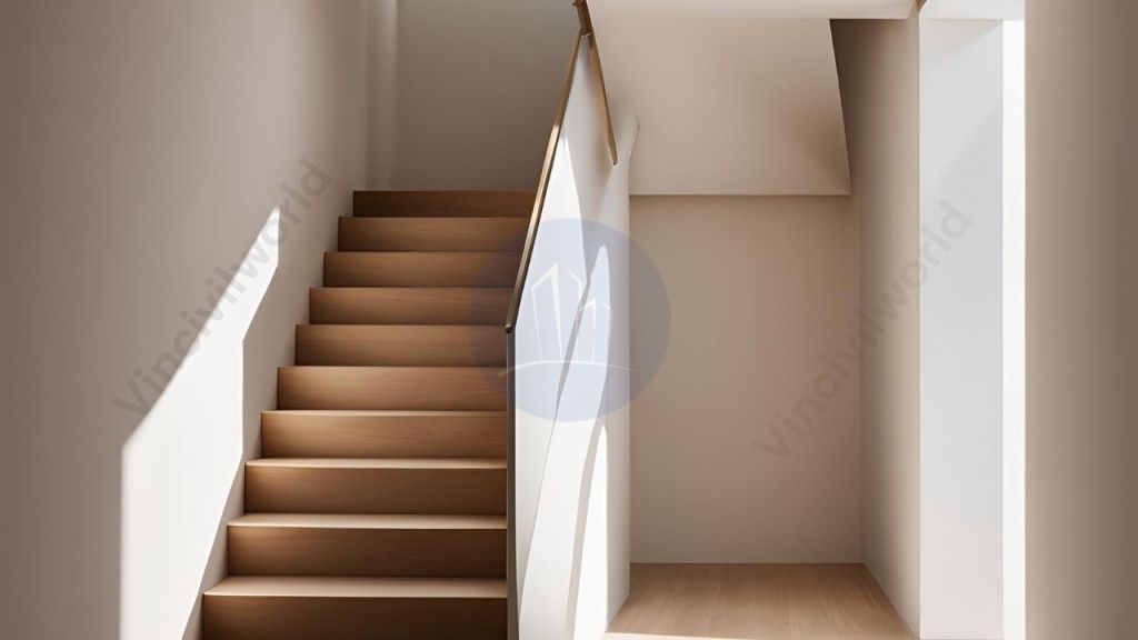
Dog legged staircase

Disadvantages of Dog legged Staircase

  • The construction of these stairs are not easy
  • The handrails need very careful planning.

Features of a good staircase

  • Staircase location selection has to ensure sufficient light and ventilation and easy access from all the rooms.
  • A single flight should have a minimum of three risers and a maximum of 16 risers.
  • Stair angles (Pitch) should be anywhere between 25 degrees to 40 degrees. Landings have to be provided categorically to manage the pitch.
  • The landing width should not be less than the width of the stair flight.
  • The riser height should be uniform for all flights between landings and floors. This uniformity helps maintain a rhythm while ascending and descending.

Types of Dog Legged Staircases

  • Dog-legged staircase with enclosed space beneath – Landing area closed and used for storage or services
  • Dog-legged staircase with open well space – A small gap or well left between the two flights
  • Dog-legged staircase with half-space landing – Landing placed midway to change direction by 180°
  • Dog-legged staircase with quarter-space landing – Used when a slight direction change is required
  • Dog-legged reinforced concrete staircase – RCC structure for strength and durability
  • Dog-legged wooden staircase – Used in residential interiors for better aesthetics

Design of Dog legged Staircase

How to design a staircase ?

Maximum size of riser is 190 mm for residential building and 150 mm for other buildings

Maximum size of thread is 250 mm for residential building and 300 mm for other buildings

In this example we are considering floor to floor height as 3 mtr

Height of Floor = 3 mtr (Floor to Floor)

Step 1

How to find the Number of Risers

Maximum height of Riser is 190 mm : Assume 175 mm as riser height

Total number of risers = 3000/175 = 17.14 risers say 17

Riser height assuming 17 risers = 3000/17 = 176.47 mm

Thread = Riser – 1 = 17-1 = 16 nos

Input details

Riser = 17 nos ( 17.47 mm)

Thread =16 nos (250 mm)

For first landing will take 9 Riser and 8 thread

For design details of dog legged staircase and layout please watch the video.
Soil Nailing – Installation,advantages and applications

Soil nailing is a slope protection technique for supporting unstable natural slopes and over steeping of existing slopes. Soil nails are reinforcing passive elements drilled and grouted sub-horizontally in the ground. They are used to support excavations in soil, or soft and weathered rock and slope protection works.

Soil nails are steel bars inserted into soil to reinforce slopes, embankments, or excavation walls. By stabilizing the ground, soil nails prevent landslides and erosion. This cost-effective technique strengthens soil structures. It is widely used in geotechnical engineering for construction. Additionally, it is used for retaining walls and slope stabilization projects.

Soil nail walls are used as permanent earth-retaining structures in highway projects. They can also be constructed as temporary structures in roadway work when used as shoring of deep excavations.

  1. Components of soil nail and its function
    1. Tendons
    2. Grout
    3. Installation of facing 
  2. Applications of soil nails
  3. Feasibility of soil nail
  4. Advantages of soil nails over other retaining systems
  5. Key Takeaways
  6. Conclusion

Components of soil nail and its function

Components mainly constitutes installing passive reinforcement without any post tensioning in existing ground know as nails. Soil nails are later grouted if they are installed in drilled holes. Soil nails using solid bar drilling system do not need grouting. Hollow bars, such as the sacrificial hollow bar system, drill and grout simultaneously and also do not require additional grouting. Let us go in detail each and every component of soil nailing system.

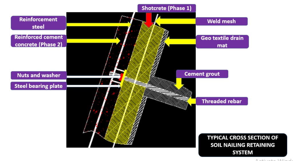
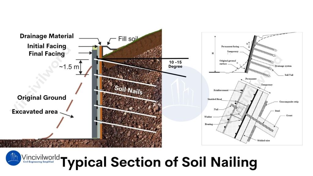
Typical cross section of soil nail
Illustration depicting a typical section of soil nailing, showing components like soil nails, drainage material, initial and final facings, and the relationship between the original ground and the excavated area.
Typical section illustrating soil nailing techniques, showing installation details for reinforcement and drainage.

Tendons

They are the ground reinforcing elements and are equivalent to steel bars. Tendons can handle tensile stress during the lateral movement and deformation of retained soil. They also manage external loads in the service stage, such as surcharge loads and traffic loads.

There are two methods of fixing soil nails or reinforcement bars.

a) Holes are drilled and pressure grouted with fully threaded bars embedded inside.
b) Using sacrificial drill bits where drilling and grouting will be done simultaneously and the sacrificial drill bit is converted to rebar.

Grout

Normal OPC cement mixed with water is used for grouting. The function of grout are

a) Transfers shear stress between the ground and tendons and

b) Corrosion protection for rebars.

Installation of facing 

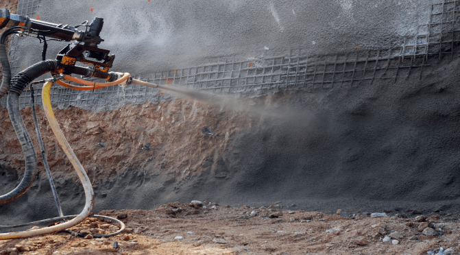
Soil nail construction is done from top to bottom. Every nail is installed with anchor plates or bearing plates.
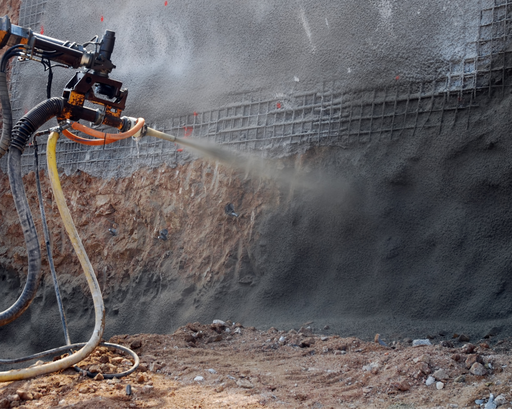
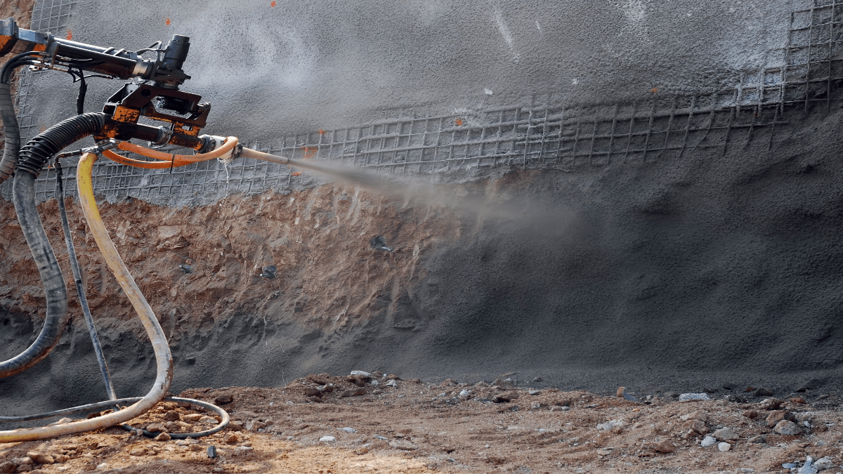
First, a single row of soil nails is installed after excavating the surface. Excavate further and install the second layer of soil nails as per design. Once you reach a reasonable height, soil can free stand (1-2 meters) for at least 2-3 days. Then the next phase of the shotcreting process will start.

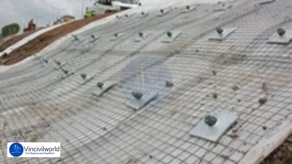
soil nailing
Close-up of a soil nailing installation showing reinforcing mesh and anchor plates on a sloped surface for slope stabilization.
Installation of welded wire mesh and bearing plates for soil nail reinforcement, ensuring slope stability and protection.

a) First face shotcrete on soil surface

A geotextile drain matting is placed over the soil. Then, it is followed by welded wire mesh as shown in the figure. Rebar stiffeners are sometimes provided to strengthen the shotcrete against punch shear forces. On completion of the first phase of shotcreting bearing plates with beveled washers are installed over the shotcrete surface.

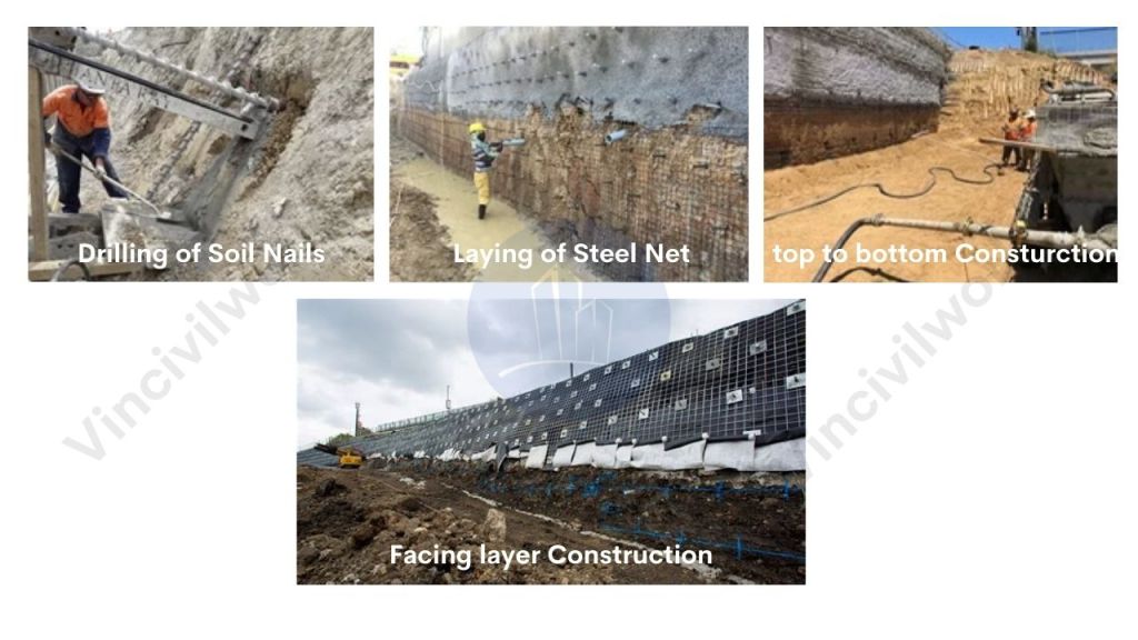
Image showing the drilling of soil nails in a slope stabilization project.
Steps in soil nailing process: drilling, laying steel net, top-to-bottom construction, and facing layer construction.

b) Second phase of reinforced concrete

If required as per design, the first layer is covered with a second phase of reinforced concrete. This is shown in the figure. This concrete covers the nail head.

Applications of soil nails

Soil nails are one of the most economical and feasible tops to bottom constructed retaining walls system. They are technically feasible, fast, and reliable slope protection and earth retaining system. Soil nails offer a perfect cost-effective system for temporary retaining walls for deep excavations..

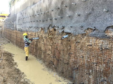
Construction worker applying shotcrete to a soil-nailing wall structure for slope stabilization.
Worker applying grout in a soil nailing installation, reinforcing a slope for stabilization.
  • High way cut excavation of hilly areas
  • Road widening under an existing bridge end.
  • Repair and reconstruction of existing retaining structures.
  • Temporary or permanent deep excavations in urban areas.

Feasibility of soil nail

Before confirming the soil nail system please ensure the following parameters at the site.

  • Soil should be able to free stand at a height of around 1-2 mtr. It must remain unsupported for a minimum of two days.
  • All soil nails within a cross-section will be above the water table.
  • If the soil nails are not located above the groundwater table, the groundwater should not negatively affect the excavation face. It should not harm the bond between the ground and the soil nail itself.
  • They can be used for almost all types of soils. This includes stiff, sandy, or hard clay. They are also applicable to dense sand and gravel areas, as well as evenly weathered rocks.
  • Avoid using soil nails in dry, poorly graded cohesion-less soils. Do not use them in soils with a high groundwater table, or in soils with cobbles and boulders. They are unsuitable for soft to very soft fine-grained soils, highly corrosive soils, and weathered rock with unfavourable weakness planes, etc.

Advantages of soil nails over other retaining systems

  • Soils nails require very little workspace comparing with any other retaining systems.
  • The operations are mostly light and silent and there is no disturbance to the traffic and people residing nearby.
  • Soil nails do not need any foundation or any structural whaler beams at the bottom like cantilever and anchored retaining walls.
  • With the soil nailing method, we can reduce the duration of work, and fewer materials are consumed in this process.
  • They are so flexible and easily customizable and nail location can be easily adjusted on encountering any obstructions.
  • Small equipment is used for soil nailing works.
  • They can accommodate differential settlements and deflection of soil nails are usually within tolerable limits.
  • They are more cost-effective than any other retaining wall system. This is because shotcrete of minimal thickness is used, unlike the heavy structural walls in other retaining wall systems.

Key Takeaways

  • Soil nailing is a slope stabilization method used in construction and excavation to reinforce soil structures.
  • Soil nails are steel bars installed sub-horizontally in the ground to prevent landslides and erosion.
  • The components of soil nails include tendons and grout, which provide reinforcement and corrosion protection.
  • Installation begins from the top, with each layer secured with anchor plates, followed by shotcreting.
  • Applications of soil nails include highway cut excavations, road widening, and deep excavations in urban areas.
  • Soil nailing is cost-effective, fast, and requires minimal workspace compared to other retaining systems.
  • This technique is not suitable for poorly graded, cohesion-less soils or areas with high groundwater tables.

Conclusion

Soil nailing is a versatile method for reinforcing slopes and retaining walls. It offers significant advantages in various geotechnical applications. It is particularly useful for highway projects, deep excavations, and slope stabilization. In these scenarios, soil nails provide crucial support to prevent landslides and erosion. The technique’s minimal workspace requirements, cost-effectiveness, and adaptability to different site conditions make it a popular choice in construction. Soil nails are most effective in soils that can stand unsupported for short periods. They should be used with caution in cohesion-less soils or areas with high groundwater levels. Overall, soil nailing offers a reliable solution for stabilizing slopes while maintaining project timelines and budgets.

Destructive tests (DT) on hardened concrete – Types

Destructive tests (DT) and Non-destructive tests (DT) are the tests done on hardened concrete. Destructive tests on concrete are essential for determining the strength and durability of hardened concrete. These tests evaluate how concrete performs under stress and give critical data for assessing the quality of a structure.

Destructive concrete testing involves breaking or damaging samples to measure their ultimate strength. Common types of destructive concrete tests include compressive strength tests, split tensile tests, and flexural tests. Testing of hardened concrete ensures that it meets design specifications and structural requirements. These tests for hardened concrete offer reliable insights into performance, making them crucial for quality control in construction. Destructive tests of concrete help identify potential weaknesses, ensuring long-term durability and safety of structures.

Concrete is the oldest and most important construction material in the world. Testing of the concrete plays an important role to know the strength, durability and condition of the structure. This article is about the types of Destructive concrete tests and non-destructive tests done on hardened concrete.

  1. Types of tests on hardened concrete
    1. Destructive tests on Hardened Concrete
  2. Significance of Destructive tests on hardened Concrete.
  3. Types of Destructive tests for hardened Concrete
    1. Compressive strength test of concrete
    2. Splitting tensile strength test on hardened Concrete
    3. Flexural strength test 
  4. Key Takeaways
  5. Conclusion

Types of tests on hardened concrete

Tests on hardened concrete are classified into two types.

This article we will discuss about the Destructive tests on hardened Concrete. For Non destructive tests on Hardened Concrete please refer our article..

Also Read : Non destructive tests on Hardened Concrete.

Destructive tests and Non-Destructive tests are done to determine the important properties of concrete. These properties include but not limited to compressive strength, flexural strength, tensile strength etc.

Destructive tests on Hardened Concrete

The quality of concrete is important for construction. Hardened concrete attains strength as it matures. The destructive test of concrete helps to understand the behavior and quality by breaking the test specimen at certain loads. The primary step of the destructive test is to cast test specimens from freshly made concrete.

The destructive testing method is suitable and economically beneficial for the concrete specimens that are produced at a large scale. The main intention of destructive tests is to investigate the service life. They aim to detect weaknesses in the design that might not show under normal working conditions. It includes methods where the concrete specimen is broken so as to determine mechanical properties i.e. hardness and strength. This type of testing is very easy to carry out, easier to interpret, and yields more information.

Also read : Concrete mixing – Types and objectives

Significance of Destructive tests on hardened Concrete.

Concrete is a basic construction material, So it should be capable to withstand heavy loads. The concrete test results mainly depend on the cement strength, water-cement ratio, concrete quality etc. The main objectives of the hardened concrete test are as follows.

  • Quality control
  • Acceptance of concrete
  • Evaluation of curing
  • To provide information on the use of sand and aggregate.
  • For evaluating the uniformity of concrete
  • Estimates the concrete quality with standard requirements.
  • To determine the uniform stress distribution.
  • Investigating the behavior of concrete.
  • For determining the in-place concrete strength.
  • Age of concrete, etc.
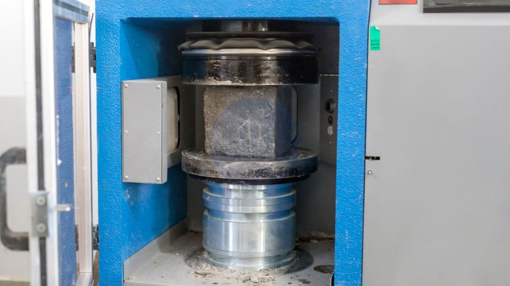
Destructive test -Compressive test on concrete
Compressive test on hardened concrete
Compressive test on concrete

Types of Destructive tests for hardened Concrete

The main intention of destructive tests is to investigate the service life. They aim to detect the weakness of design that might not show under normal working conditions. These tests determine the compressive, flexural and tensile strength of concrete. There are different types of tests available to examine the hardened concrete. They are as follows.

This article focuses on Compressive strength test and Flexural Strength test on Hardened Concrete . For splitting tensile strength test please refer to our article mentioned below.

Also Read : Splitting Tensile Strength Test on Hardened Concrete

Compressive strength test of concrete


The compressive strength test of concrete is a crucial method in destructive concrete testing. It assesses how much load a concrete sample can withstand before failure. In this test, hardened concrete specimens are subjected to increasing pressure until they crack. This test helps evaluate the structural integrity of the concrete. As a major type of destructive concrete test, it offers vital data. This ensures the quality and performance of concrete in various construction applications.

Compressive strength of concrete is the ability of the concrete to withstand loads without cracking or deformation. The concrete specimen to conduct this test should be either cylindrical or cubic. The apparatus for performing this test is a Compression testing machine. The relevant IS code for this test is IS 516-1959. The load at which the specimen fails measures its strength. 

Compressive strength of the concrete = Load at which the concrete breaks / Cross-sectional area of the specimen

The unit of compressive strength of concrete is N/mm^2. The test should be done at 7, 14 & 28 days. 

For more details : Compressive strength of concrete -significance and test procedure

Compressive strength test of concrete

Splitting tensile strength test on hardened Concrete

The splitting tensile strength test is one of the tests on hardened concrete for determining its tensile strength. Concrete is a durable construction material. Under tension, concrete is brittle in nature. Therefore it causes cracks and deteriorates. The splitting tensile strength test measures the concrete tensile strength. For this test, we use cylindrical specimens with 150 mm diameter and 300 mm height. 

The tensile strength of concrete is 

Splitting tensile strength of concrete, T= 2P/ Ω LD

The unit of tensile strength is N/mm. The IS 5816: 1999, ASTM C496 gives the standard aspects for this test. 

Also Read : Splitting tensile strength test on concrete- Significance and test procedure

Flexural strength test 

The flexural strength test and splitting tensile strength test are almost the same. Because both the tests measure the tensile strength of concrete. The flexural strength test of concrete measures the tensile strength of concrete through an indirect method. The relevant codes for this test are ASTM C293 & ASTM C78. This test measures the ability of concrete to resist failure in bending. The modulus of rupture is the measure of tensile strength. Its unit is MPa or psi. 

Modulus of rupture, MR = 3PL/ 2bd^2

Where, 

P is the Ultimate applied load, L is the span length, b & d is the average width and depth of specimen at fracture. 

Key Takeaways

  • Destructive tests on hardened concrete help assess strength and durability.
  • Compressive strength test is the most common destructive concrete testing method, crucial for evaluating load-bearing capacity.
  • Split tensile strength tests measure concrete’s resistance to tension.
  • Flexural strength tests assess concrete’s ability to resist bending, providing data on tensile strength.
  • Testing of hardened concrete is vital for ensuring the quality and performance of concrete in construction.
  • The results from tests for hardened concrete offer insights into the structural integrity of concrete elements.

Conclusion

Destructive tests on hardened concrete are critical for assessing the strength, durability, and performance of concrete structures. Methods like the compressive strength test, splitting tensile test, and flexural strength test provide valuable data. They show how concrete will perform under different stresses. These types of destructive concrete tests identify weaknesses that may not be visible under normal conditions. This ensures the long-term stability and safety of concrete structures. Destructive concrete testing provides essential insights into the quality of the material. It subjects samples to failure. This supports better design and construction practices.

These are the major tests done on hardened concrete for determining the strength of concrete. As concrete is the basic ingredient of all structures , the quality has to be ensured to maintain the structural stability and life.

Traffic signals in India- An intensive study

Traffic signals in India. What is the first thing that comes to your mind when you hear the civil engineering subject? The one who disturbs the rhythm of your journey without your permission, right? Jokes apart, it plays a relevant role in the traffic management of the country. Being wide and heterogeneous in nature, it is not a cakewalk to control the huge population including you and me.

Before we get into the details, let me tell you something important. Traffic signals in India and traffic signs are not the same!

  1. Traffic sign v/s signal
  2. The importance of traffic signals
  3. Mechanism of traffic signals in India
  4. Advantages of traffic signals in india
  5. Types of traffic signals
    1. Traffic control signals
      1. Fixed time signal
      2. Manually operates
      3. Traffic actuated
    2. Pedestrian signals
    3. Special traffic signals
  6. Types of traffic signal system
  7. Warrants for traffic control signal in india

    Traffic sign v/s signal

    There is often a misconception that traffic signals and signs are the same. But the truth is that both are traffic control devices, but different. Traffic signs are placards provided to guide you in the journey. Signals are placed only at the main intersections to manage the traffic.

    For example, imagine a junction where heavy traffic is found usually in the north-south direction. If there is no much traffic in the east-west direction, traffic signals are not required at the junction. Yeah, simple logic.

    The importance of traffic signals

    TRAFFIC SIGNALS IN INDIA
    Traffic signals in india

    Growing traffic density is a significant issue. Insufficient expansion of available road space also contributes. These factors have resulted in congestion during peak hours. They have caused related delays on urban roads around the world. It results in increased travel time, which reduces the performance of the transport network. This problem is more serious on urban roads with frequent intersections. Intersections are the main points of conflict for traffic movements. Traffic signals at the main intersections can curb the situation.

    Mechanism of traffic signals in India

    The design of signals will be straightforward. It shows a green light where there is less traffic. It shows red where there is more traffic. It also considers the pedestrians who may cross the road. It allots a minimum of 10 to 15 seconds for their crossing. Another interesting fact it considers is that the overall waiting time should not exceed 120 seconds in normal situations. This is the average tolerance level of humans.

    Advantages of traffic signals in india

    • Provide orderly movement
    • Minimizes the number of conflicting movements
    • Increase capacity
    • Interrupt heavy traffic to allow other traffic to enter or cross
    • The coordinate continuous movement of traffic at the desired speed
    • Promote driver confidence

    Okay. Let’s see the varieties now.

    Types of traffic signals

    Traffic signals are broadly classified into three.

    Traffic control signals

    These are the signal lights in red, green and yellow. Red to stop, green to go and yellow to get ready. Obviously, you have seen the rangoli of colors in your life.

    Traffic control signals are further divided into 3.

    Fixed time signal

    These signals operate at fixed time periods without considering the real time traffic.

    Manually operates

    This type of signals are manually operated which makes it more reliable.

    Traffic actuated

    This includes semi actuated and fully actuated signals. The timings are real time.

    Pedestrian signals

    These are the signals for pedestrians who cross the road or walk along the footpaths.

    Special traffic signals

    All other signals which don’t come in the previous categories belong to this type.

    Types of traffic signal system

    The whole system of traffic signals in India are divided as follows.

    1. Simultaneous system
    2. Alternate system
    3. Simple progressive system
    4. Flexible progressive system

    We have seen different faces of signals. Now, let me get you the warrents for traffic control signals.

    Warrants for traffic control signal in india

    TRAFFIC SIGNALS IN INDIA
    Traffic signal in india

    1. Minimum vehicular volume warrant

    Case 1- The average traffic volume for 8 hours should be at least 650 vehicles/hr. This applies to both approaches on major streets with a single lane. It should be 800 vehicles/hr on streets with 2 or more lanes.

    Case 2- Minor street (One direction atleast 200 veh/hr- single lane

                                                                       250 veh/hr- two lanes

    Case 3- >60kmph, 70 percent increase in major case

    2. Interruption to continuous traffic flow on major street with 1000- 1200 veh/hr that there is undue delay or hazard to traffic on minor road with a traffic 100- 150 veh/hr in one direction only during any 8 hours on average day

    3. Minimum pedestrian volume movement

    4. Accident experience warrant

    5. Combination of warrants

    Lastly, in areas where there is huge traffic, ramps are preferred. But ramps are not suitable to heterogeneous traffic through some of the planned cities have implemented them. Its better to use flyovers and over bridges in these cases.

    MUST READ: Basic of civil engineering; Simple and in-depth guide

    Anchored retaining walls/Tie back system-Advantages

    Anchored retaining walls, also known as tie-back systems, are essential structural components used in construction. They are mostly used to stabilize earth and as support structures. Anchored Retaining walls deliver lateral support to walls. They prevent soil from shifting or eroding. These walls are commonly used in applications like deep excavations, embankments, and hillside retention etc.

    This article will cover the different types of anchored retaining walls/ tie back systems. This article will also discuss the design principles and the installation process and explore the advantages and applications of using tie-backs in modern construction projects. An anchored retaining wall system is a structural element. This is installed through the rock or soil and transfers the tensile forces developed in the structure to the ground. Anchored retaining walls are often slimmer than all their counterparts like gravity walls and cantilever retaining walls.

    1. What is an Anchored Retaining Wall?
    2. Key Components of Tie-Back Retaining Walls
      1. Retaining Wall
      2. Anchors
    3. Design Principles of Anchored Retaining Walls
      1. Safety Factors
      2. Soil Type
      3. Load Calculations
      4. Anchor Spacing
    4. Types of Tie back systems
      1. Gravity Retaining Walls with Anchors
      2. Cantilevered Retaining Walls with Anchors
      3. Sheet Pile Walls with Tie-backs
      4. Soil Nail Walls
      5. Braced Walls
    5. Anchored retaining wall or Tie back system – Installation method.
    6. Fixing of anchors in a tie-back system
    7. Advantages of anchored retaining walls
    8. Key Takeaways from Anchored Retaining Walls/Tie-Back Systems
    9. Conclusion

    What is an Anchored Retaining Wall?

    An anchored retaining wall uses additional reinforcements for stability. Often, these reinforcements are steel cables or rods. They are known as anchors or tie-backs. The tie-backs are driven deep into the ground behind the wall. They anchor the wall securely. This allows it to resist pressure from the retained soil. These walls are ideal for supporting large vertical loads. They are particularly effective when space constraints limit the use of other retention methods.

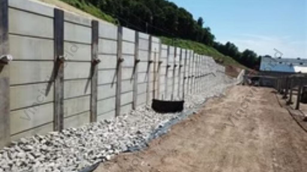
    Anchored retaining wall
    Anchored retaining wall

    Key Components of Tie-Back Retaining Walls

    Tie-back systems rely on two main components: anchors and retaining walls.

    Retaining Wall

    The wall itself is usually made of materials like concrete, steel, or timber. It serves as the primary barrier to resist the pressure exerted by the retained soil.

    Retaining wall with tie back systems

    Anchors

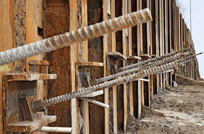
    These are steel rods or cables inserted into the soil behind the wall, providing tension to counteract the lateral forces exerted by the earth. The anchors are fixed at the back end using a variety of methods, including grouting or mechanical anchoring.

    Design Principles of Anchored Retaining Walls

    The design of an anchored retaining wall involves several key considerations to ensure structural integrity and durability:

    Safety Factors

    A safety factor is applied in the design to account for unforeseen stresses or variations in soil conditions.

    Soil Type

    Understanding the soil characteristics is crucial for determining the number, length, and type of anchors needed.

    Load Calculations

    Engineers must calculate the lateral earth pressure and any additional loads (such as water pressure) to determine the anchor capacity.

    Anchor Spacing

    Proper spacing of tie-backs is essential for uniform load distribution and wall stability. The design will vary based on wall height and soil type.

    Types of Tie back systems


    There are several types of anchored retaining walls, each suited for different applications

    Gravity Retaining Walls with Anchors

    Gravity retaining walls rely primarily on their own weight to resist the lateral pressures exerted by the retained soil. These walls are usually constructed from concrete, masonry, or stone. They are often designed with added anchors for additional stability. This is especially important in situations with significant soil pressure.

    The anchors provide a secure connection to the soil behind the wall. This connection enhances the wall’s ability to withstand overturning and sliding forces. Gravity walls are typically employed for low-height structures where space allows for their robust base design. They are simple to construct and cost-effective for lower applications.

    Cantilevered Retaining Walls with Anchors

    Cantilevered retaining walls have a unique design. They include a vertical wall supported by a slab. The system also includes a footing. This design efficiently utilizes the wall’s weight and structural integrity. It allows the wall to resist lateral forces. Anchors, which are embedded into the ground behind the wall, aid in this resistance. The additional support provided by the anchors is crucial for taller walls where lateral earth pressures are more significant.

    Cantilevered walls are often preferred where space is constrained. They can be designed to accommodate various soil types. This makes them versatile for different applications.

    Sheet Pile Walls with Tie-backs

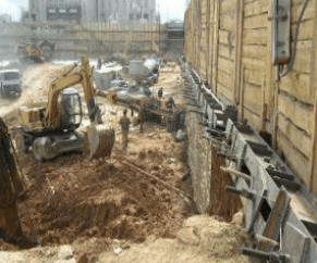
    Sheet pile walls are constructed from interlocking steel or concrete sheets. These sheets are driven into the ground to create a barrier against soil and water. This type of wall is particularly effective in deep excavations. It is also suitable for waterfront construction projects. Limited space makes conventional retaining methods impractical in these scenarios. Tie-backs are incorporated to enhance the stability of sheet pile walls. They provide tension forces that counteract lateral earth pressures.

    Sheet pile retaining wall with tie back using anchors

    These tie-backs are anchored into the soil or bedrock behind the wall. This system is highly effective in urban settings. It also works well in areas with high groundwater levels. Sheet pile walls with tie-backs offer a reliable solution for managing soil movement and maintaining structural integrity in challenging environments.

    Soil Nail Walls

    This wall type incorporates soil nails, which are long steel bars inserted into the soil, providing stability through tension. Soil nail walls are ideal for steep slopes and challenging sites. They are cost-effective for moderate heights. They are also less intrusive than other wall types. They allow for better drainage and less disruption to the surrounding area​

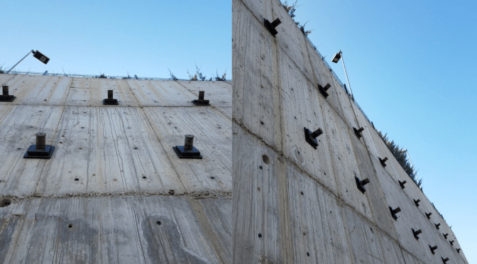
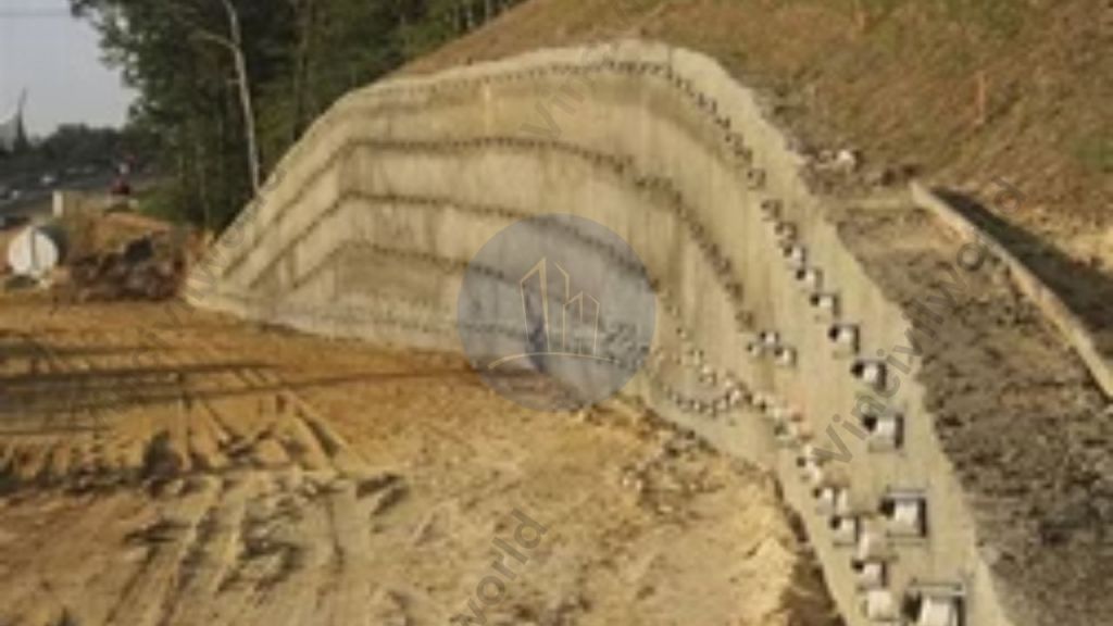
    Soil Nail walls

    Braced Walls

    Often used in deep excavations, these walls are supported by braces or struts connected to the ground. Braced walls can handle high loads and are versatile for various soil conditions. They require careful planning for spacing and materials to ensure structural integrity while managing excavation risks​(

    Anchored retaining wall or Tie back system – Installation method.

    Anchored retaining wall is also known as a tie-back system. They are used in combination with cantilever retaining walls, piled retaining walls, sheet piles, tangent walls, etc. The Tie-back system enhances the stability of the structure. It plays an important role in equipping the walls to handle additional loads.

    The anchored walls are installed when the load acting on the structure is high. In this case, the design of cantilever retaining walls / piled retaining walls/ sheet piles etc seems uneconomical. Moreover, it is difficult to accommodate the foundation and structures due to space constraints. For enhancing the load-carrying capacity and economising the structure additional anchors are embedded in the earth to be stabilized. These anchors in combination with the main structure negotiate the loads.

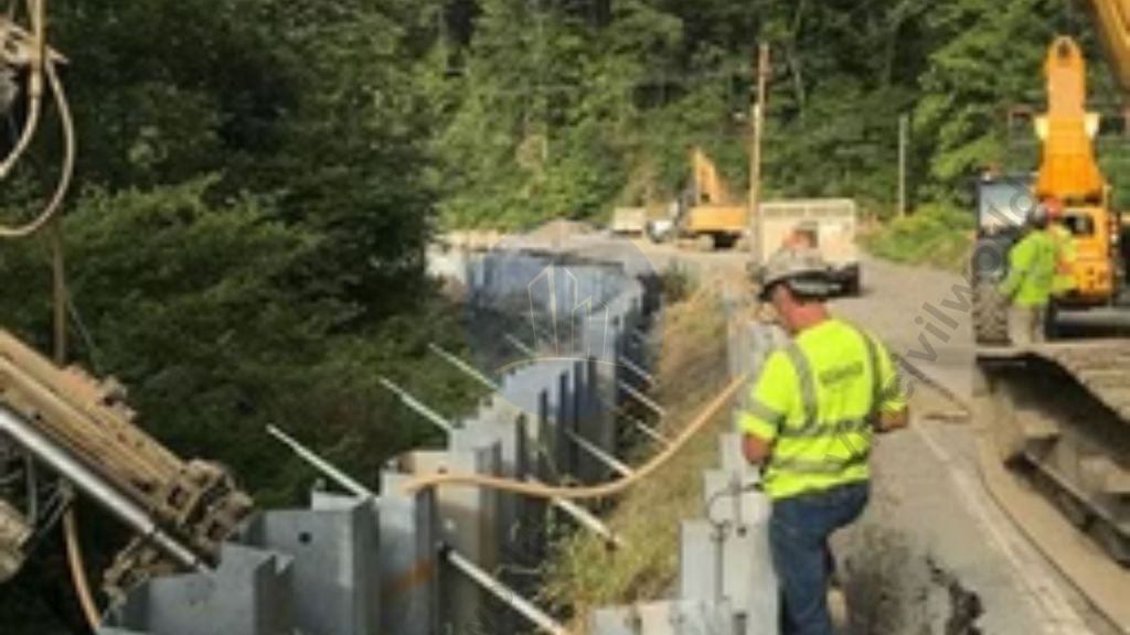
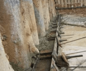
    Piled retaining walls with tie back system

    Related posts from vincivilworld

    Also Read : Soil Nailing – Installation, Advantages and applications.

    Fixing of anchors in a tie-back system

    One end of the tieback is anchored to the wall and another end is driven to the soil/rock. Sometimes stable concrete structures are driven into the ground to get a good anchorage. Tiebacks and drilled through the wall to the soil at an angle of around 15-45 degrees.

    After drilling the holes ties or struts are provided inside the drilled holes and pressure grouted to give greater stability. In the case of piled retaining walls, the tie-back system is drilled through whaler beams installed between the piles as shown in the figure. Steel rods are placed inside the drilled holes and grouted under high pressure. This creates a bulb-like anchor at the rods’ end, preventing the tie-backs from pulling out the load.

    These walls can be very tall and support high loads and are ideal for smaller areas that need earth retention.

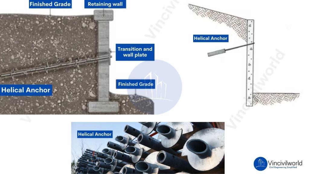
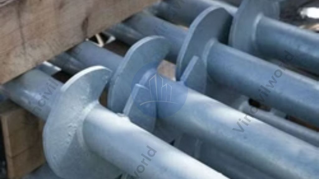
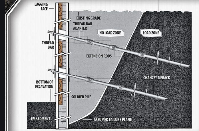
    Some times instead of rods, helical anchors are also driven to in place and the capacities are decided by the torque required for tightening the anchors.

    Anchored retaining wall - Typical section of helical anchors
    Typical section of helical anchors

    The main purpose of the tieback system is to develop a strong soil mass to resist external failure modes. The moment of soil and wall has to be restricted to get better serviceability.

    Advantages of anchored retaining walls

    • Mostly used for slope protection and retaining earthworks of deep excavations.
    • Thin walls or very light structures can be designed in combination with anchored walls.
    • Anchored walls are one of the most economical systems of earth retention.
    • Combination with sheet piles, cantilever retaining walls, piled retaining walls etc are very useful for deep excavations. They help in providing a safe working area.

    Key Takeaways from Anchored Retaining Walls/Tie-Back Systems

    1. Slope Protection: They are primarily used for stabilizing slopes and retaining earth during deep excavations.
    2. Thin Wall Design: Anchored retaining walls allow for thinner and lighter wall designs without compromising strength.
    3. Cost Efficiency: These systems are highly economical for retaining earth compared to other methods.
    4. Versatility: They can be used with sheet piles, cantilever, and piled retaining walls for various deep excavation projects.
    5. Space Saving: Suitable for areas with space constraints while maintaining structural integrity.
    6. Structural Stability: Anchored walls provide lateral support and resist significant external loads, ensuring safety during excavation projects.

    Conclusion

    Anchored retaining walls, or tie-back systems, play a crucial role in modern construction. Their design provides lateral stability while allowing for thinner and more cost-effective structures. They are particularly useful for deep excavations, slope retention, and projects where space is limited. The combination of anchors with retaining walls makes them adaptable to various applications, from sheet piles to cantilever walls. Anchored retaining walls are among the most economical solutions for ensuring soil stability. They offer versatility, especially in urban or constrained environments. Their integration in construction projects ensures structural safety, cost savings, and effective use of space.

    For more details about the retaining walls watch the below video.
    Youtube video – 15 Types of Retaining wall systems

    Types of retaining walls

    Types of Levelling in Surveying – Uses and advantages

    Types of levelling in surveying include direct levelling, trigonometric levelling, barometric levelling, and stadia levelling. Direct levelling is the most commonly used method. It involves using a level and staff to determine height differences between points. Trigonometric levelling uses angles and distances measured with a theodolite. Barometric levelling relies on atmospheric pressure readings, while stadia levelling involves using a telescopic instrument to measure distance. Each method serves different applications based on the project requirements. Levelling surveying ensures accurate elevation data for construction, roadworks, and drainage systems. The advantages of levelling include precise ground profiling, improved accuracy in projects, and efficient data collection. Define levelling as a key technique for enhancing surveying reliability.

    Types of levelling – Leveling is a branch of surveying that deals with computing and determining the relative heights between different points with respect to the datum. The purpose of leveling is for determining the elevation of a point and establishing the same at a given elevation. Moreover leveling deals with the computation of measurements in the vertical plane. There are different types of leveling in Surveying. In this article, we will discuss the purpose advantage and types of leveling.

    1. Purpose of levelling in Surveying
    2. Types of levelling
      1. Barometric levelling – Types of levelling
      2. Trigonometric levelling – Types of levelling
      3. Stadia levelling – Types of levelling
      4. Direct levelling
        1. Simple levelling
        2. Differential levelling
        3. Profile levelling
        4. Reciprocal levelling
        5. Precise levelling
    3. Key Takeaways: Types of Levelling in Surveying
    4. Conclusion

    Purpose of levelling in Surveying

    The purpose of levelling in surveying is to determine the relative height of different points on the earth’s surface. Levelling ensures accurate measurements of elevations, helping in the design and construction of roads, buildings, and drainage systems.

    • Mapping and contouring : Preparation of accurate map layouts with elevation details.
    • Establishing Elevations : To decide the elevation of points by establishing the height differences between points.
    • To prepare contour maps.
    • Earth work : Determination of depth of cutting and filling in earthworks.
    • To make the cross-section of canals, roads, etc.
    • For establishing control points.
    • Water Flow control : Ensures proper Drainage and irrigation
    • Building Layout – Facilitates precise alignment for construction.

    By understanding the types of levelling in surveying, professionals achieve greater accuracy in infrastructure projects. This enhances the advantages of levelling techniques.

    Types of levelling

    Types of Levelling in Surveying are crucial for determining accurate elevation differences. Different methods cater to varying project needs, enhancing the advantages of levelling.Each method has distinct advantages, making levelling surveying versatile in engineering and construction projects.

    There are mainly four types of levelling in surveying. 

    • Barometric levelling
    • Trigonometric levelling
    • Stadia levelling
    • Spirit levelling or Direct levelling

    Each method has distinct advantages, making levelling surveying versatile in engineering and construction projects.

    Barometric levelling – Types of levelling

    Barometric leveling is a type of leveling. The measurement of elevation is based on atmospheric pressure by using a barometer. Therefore, we use a barometer. The main principle of Barometric leveling is the difference between the elevation of two points. This difference is proportional to the difference between the atmospheric pressure of the points. Since it is inaccurate, this method of leveling is rarely used. Because leveling takes time and the atmospheric pressure does not remain constant throughout the day. Therefore they give only a rough estimation.

    Though not as precise as other types of levelling like differential levelling, it is useful for rough elevation measurements. This method is effective over large distances where accuracy is not critical.

    The advantages of levelling using the barometric method include its simplicity and cost-effectiveness for non-critical tasks. It complements various methods of levelling in broad-scale levelling surveying projects.

    Trigonometric levelling – Types of levelling

    Trigonometric levelling is a method used in levelling in surveying to calculate the elevation. In this method, the difference in elevation is calculated using the observed vertical angle. The calculation also involves the known horizontal distance. The height difference is then calculated using trigonometric formulas. Another name of trigonometric levelling is Indirect levelling. For vertical angles, generally, we use theodolite. For horizontal distance, if the distance between the points is less, we measure using plane surveying. If the distance between the points is greater, we use geodetic observation. 

    Among the various types of levelling in surveying, trigonometric levelling is particularly useful for long-distance or high-elevation measurements. The advantages of levelling with this method include its ability to handle rough terrain and large-scale surveys. It complements other methods of levelling for projects where precision is critical.

    trigonometric levelling
    trigonometric levelling

    Stadia levelling – Types of levelling

    Stadia levelling is similar to trigonometric levelling. To determine the elevation of points, we use a tacheometer. Hence, It is an optical distance measurement method. This type of levelling is suitable in hilly regions. Stadia levelling is an accurate method of levelling. Another name of stadia levelling is Tachometric levelling. It is efficient for surveying in areas where direct measurement is difficult. The advantages of levelling with stadia include its simplicity and speed. It’s often used in combination with other methods of levelling for topographic mapping and large area surveys.

    Direct levelling

    Direct levelling is also known as spirit levelling. It is the most precise and commonly used levelling method. In this method, the vertical distance is taken with respect to the horizontal line. This determines the relative position between the points. The instruments which are used in Direct levelling are level and a levelling staff. The level consists of a telescope, level tube, levelling head and a tripod.

    It is the most accurate among the types of levelling in surveying. It is commonly used in construction and land surveys.

    The advantages of levelling using the direct method include high accuracy and simplicity in application. It’s widely used for detailed work. It also serves as a basis for more complex methods of levelling like trigonometric or barometric levelling.

    Direct levelling is further divided into …

    • Simple levelling
    • Differential levelling
    • Profile levelling
    • Reciprocal levelling
    • Precise levelling

    Simple levelling

    It is the simplest method of levelling. In this method, we place the levelling instrument between the points for determining elevation. This type of levelling is suitable if the distance between the points is less. 

    simple levelling
    simple levelling

    Differential levelling

    Differential levelling is suitable in places where the distance between the points are great. This type of levelling is also known as fly levelling. In differential levelling, the levelling station is shifted various times. 

    Differential levelling
    Differential levelling

    Profile levelling

    Another name of profile levelling is longitudinal levelling or sectioning. In this type of levelling, the points are far apart at known distances. So levelling is done at intervals along the given line. It is suitable for roads, canals, sewer lines, railways, etc. 

    profile levelling
    profile levelling

    Reciprocal levelling

    This type of levelling is done, when it is not possible to set up the level between two points. It is the accurate method of levelling. It is suitable in the place where ponds, rivers are seen. 

    reciprocal levelling
    reciprocal levelling

    Precise levelling

    This types of levelling have high precision. It is similar to differential levelling. In precise surveying, special equipment and special precaution are taken to eliminate errors. 

    Key Takeaways: Types of Levelling in Surveying

    Understanding the types of levelling in surveying is essential for accurate elevation measurements in various engineering and construction projects. The main methods include direct levelling, trigonometric levelling, barometric levelling, and stadia levelling.

    1. Direct Levelling (or spirit levelling) is the most precise method, utilizing a level and staff to determine height differences.
    2. Trigonometric Levelling calculates elevation based on angles and distances, making it suitable for long distances and rough terrain.
    3. Barometric Levelling measures elevation through atmospheric pressure differences, though it is less accurate and primarily used for rough estimates.
    4. Stadia Levelling employs a tacheometer for distance measurement, excelling in hilly regions where direct measurement is challenging.

    Each type offers distinct advantages, ensuring accurate mapping, earthwork planning, and construction alignment. By selecting the appropriate method, surveyors enhance project reliability and efficiency.

    Conclusion

    In conclusion, understanding the various types of levelling in surveying is crucial for achieving precision in elevation measurements. These measurements are fundamental to successful engineering and construction projects. Each method—direct levelling, trigonometric levelling, barometric levelling, and stadia levelling—serves specific applications and offers unique advantages. Direct levelling stands out for its accuracy, making it ideal for detailed work. Trigonometric and stadia levelling are invaluable for long distances and challenging terrains. Barometric levelling, although less precise, provides a quick solution for rough estimations over large areas. By employing the right levelling technique, surveyors can enhance the quality and reliability of their data. This leads to improved decision-making in design and construction processes. As infrastructure demands grow, we must leverage the strengths of each levelling type. This will be essential for optimizing project outcomes. It will also ensure that construction aligns with planned specifications and environmental considerations.