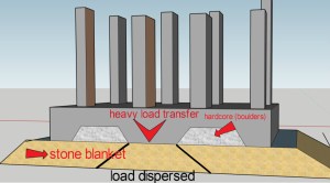
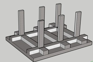
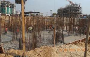
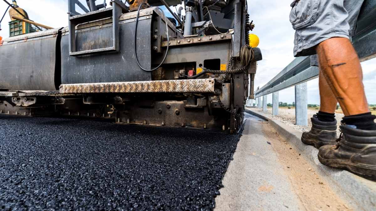
PCC concrete of Plain Cement Concrete (PCC) is without reinforcement steel. Plain cement concrete (PCC) is high in compression and very low in tension. Plain cement concrete is commonly used over the ground to keep footing reinforcement from coming into direct contact with the soil. The design mixes commonly used for Plain Cement Concrete (PCC) are 1:4:8, 1:3:5, 1:2:4, M7.5, M10 etc. PCC can also be used for grade slabs (floors) and concrete roads where the only load is compressive.
Concrete is a mixture of cement, sand, and aggregate (preferably broken stone) mixed with water in specific proportions. When poured into moulds or shuttered, the mixture consolidates over time to form a uniform mass known as concrete.
- What is PCC Concrete or Plain cement Concrete in construction?
- Properties of Plain Cement Concrete or PCC concrete
- Ingredients of Plain Cement Concrete or PCC Concrete
- Production of Plain Cement Concrete (PCC) in Construction
- Types of concrete in construction
- How to Decide On A Concrete Type
- Placing of Plain Cement Concrete (PCC)
- Precautions while doing Plain Cement Concrete (PCC)
What is PCC Concrete or Plain cement Concrete in construction?
Concrete without reinforcement steel is called Plain Cement Concrete (PCC). Generally, design mixes commonly used for PCC are 1:4:8 , 1:3:5, 1:2:4, M7.5, M10 etc. Plain cement concrete is high in compression and very low in tension.

Related posts from vincivilworld


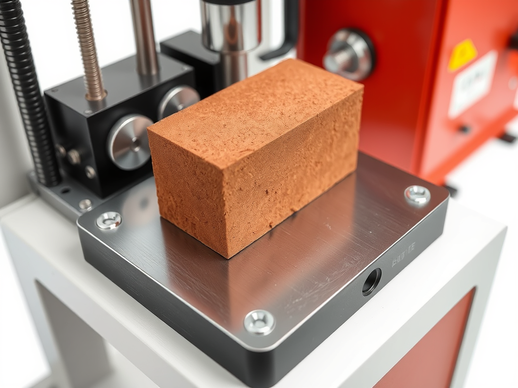
Properties of Plain Cement Concrete or PCC concrete
Plain cement Concrete (PCC) has compressive strengths ranging from 200 kg/cm2 to 500 kg/cm2. Likewise, tensile strength of PCC ranges from 50 kg/cm2 to 100 kg/cm2, and density ranges from 2200 kg to 2500 kg, depending on the grade of concrete and aggregates used.
Ingredients of Plain Cement Concrete or PCC Concrete
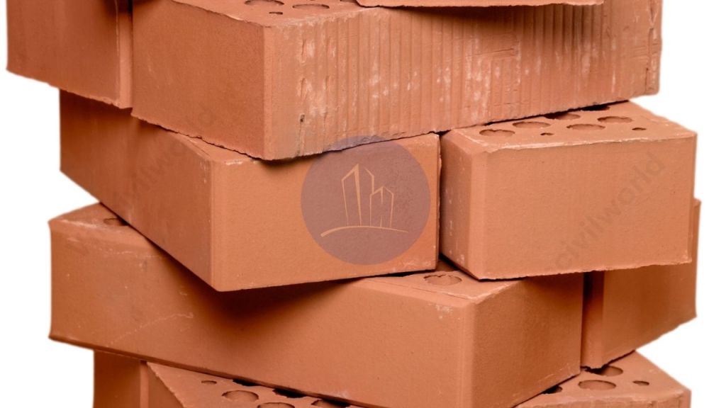
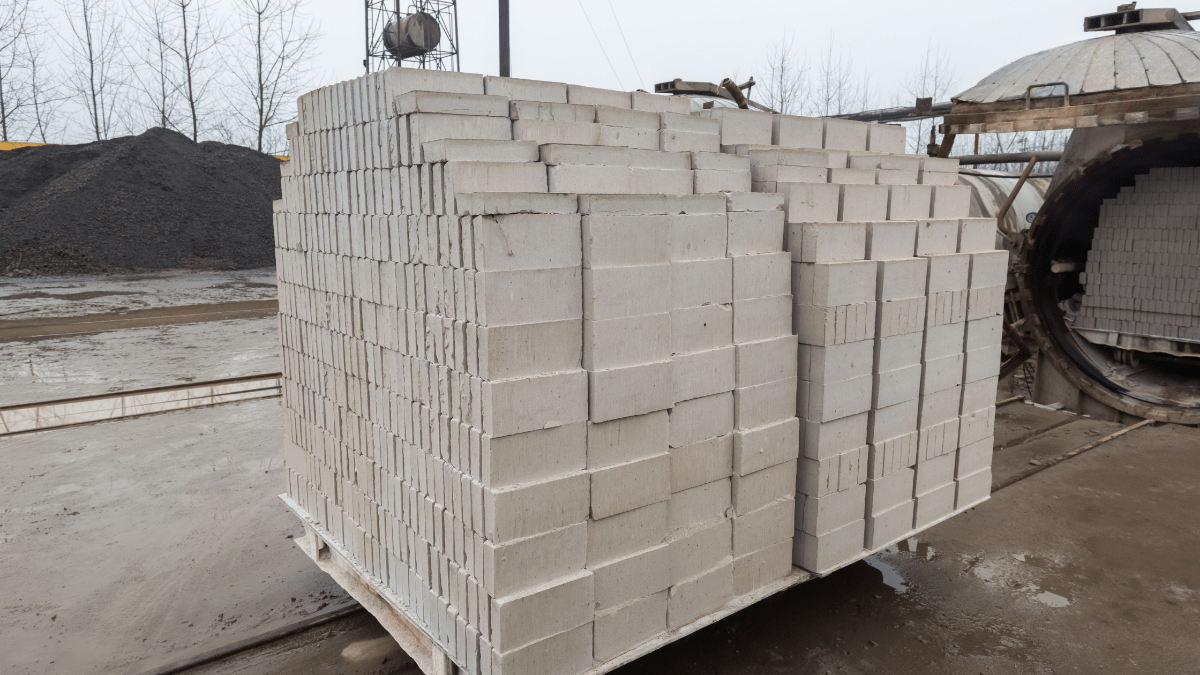
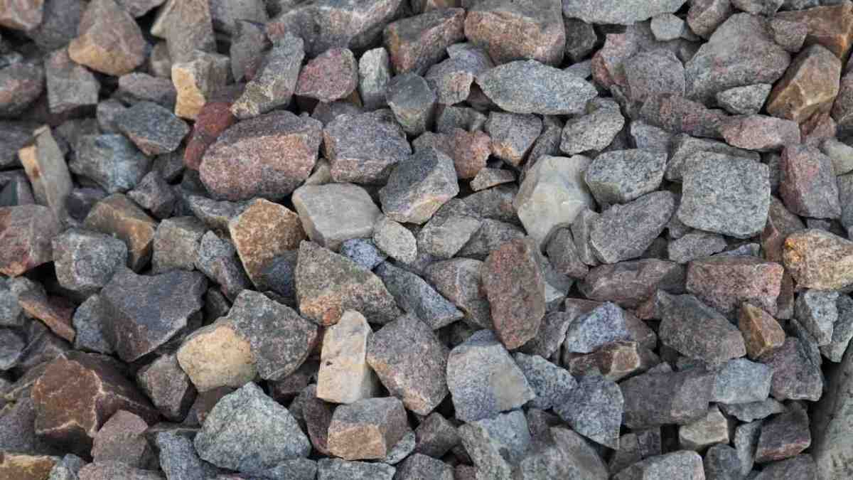
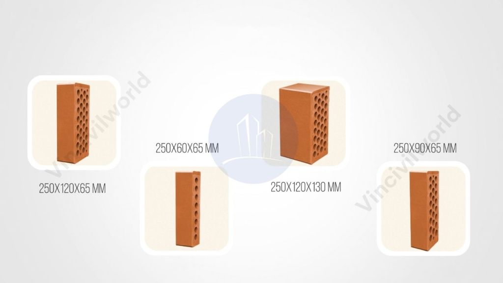
Basically, PCC is made from cement, coarse aggregate, and fine aggregate. Ordinary Portland cement is used as the binding material. Accordingly, as coarse aggregate, broken or crushed stone or brickbats must be used. However, fine aggregate must consist of coarse sand. Finally, these ingredients are combined in the appropriate proportions with potable water to make PCC.
Production of Plain Cement Concrete (PCC) in Construction
PCC can be manufactured in batching plants, mixer machines, or manually mixing. Generally, the thickness of PCC can range from 50 mm to 300 mm or more, depending on the design parameters.
Types of concrete in construction
The following are the main types of concrete used in construction

- PLAIN CEMENT CONCRETE (PCC)
- REINFORCED CEMENT CONCRETE (RCC)
- PRESTRESSED CONCRETE
- PRECAST CONCRETE
- SELF COMPACTED CONCRETE
How to Decide On A Concrete Type
The type of concrete to be used on a particular work is decided based on following conditions.
Material Availability
Normally, the raw material (aggregate, sand, cement etc) availability decides the type of concrete to be used.

Strength Required
The concrete requires different strengths for different structures. However, the strength required for the particular structure decides the type of concrete to be used.
Construction methodology to be adopted
The construction technique to be adopted for a structure decides the type of concrete. Example Pre-stressed concrete etc.
Type of structure
Most of times the type of the structure decides the type of concrete to be used.
SELF COMPACTED CONCRETE (SCC) is preferred in structures where normal pouring is restricted due to rebar congestion or access restricted pouring area. SCC, when pumped from a single point, can fill every part of the structure.
Area of application
The type of concrete shall be decided by the area where it has to be used. In some structures, the reinforcement is so dense that concrete may not pass through it. Mostly, In those cases, specially designed concrete with small-size aggregates or Self compacted concrete (SCC) may be used.
Climate and pouring conditions
The areas where there is extreme weather conditions like heavy rain , extreme cold, extreme hot specially designed quick setting concrete will be used.
Placing of Plain Cement Concrete (PCC)
The following steps are followed while placing Plain Cement Concrete (PCC)
Level marking and dressing for PCC concrete
After completing the excavation, the bottom level of the PCC shall be marked on the ground using a level machine. The centre line from the survey pillars shall be transferred to the ground where PCC has to be done. The surface shall be dressed manually to remove the loose soil the surface level to receive PCC.
Surface Preperation and shuttering
The surface shall be neatly dressed and supports has to be placed around using wooden battens. Accordingly, the battens used have to be the same size as PCC preferably. The battens shall be properly supported using proper supports (scrap steel can be used). The dressed surface shall be sprinkled with water to avoid absorption of concrete water by the soil.

Placing and Finishing of PCC Concrete
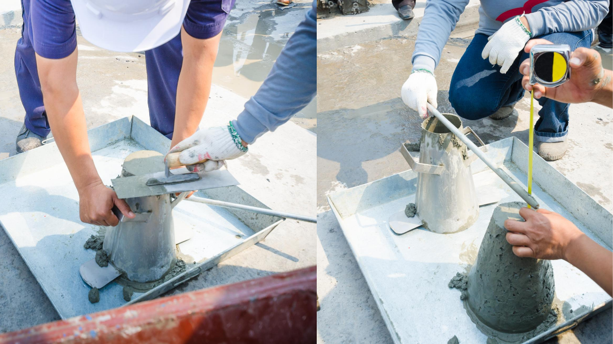
Concrete must be poured from one end to the other. For levelling purposes, level pillars at 2 metre intervals must be provided. The concrete must be levelled and rammed in accordance with the level pillars and end supports. The slump for PCC should be approximately 75 mm. Concrete must be poured within 30-45 minutes.
Precautions while doing Plain Cement Concrete (PCC)
- When excavating, take care to only excavate to the required levels. However, avoid over-excavation. Backfilling with loose earth is not recommended if the excavation depth exceeds the required depth. In that case, we can place the PCC at the required level by doing a plum concrete. Backfilling with soil and compaction with plate compactors/walk-behind rollers/or Vibro rollers, depending on the situation, is required.
- Before beginning excavation, the PCC level must be transferred to different locations. Before fine dressing with lime powder, the centerline and PCC dimensions must be marked on the ground to avoid reworks.
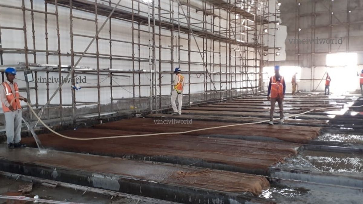
- The surface on which PCC is to be laid shall be sprinkled with water.
- Anti Termite chemical or LDPE sheets may sometimes be used before doing PCC. A confirmation has to be taken before doing the PCC from the clients/customers.
- The free-falling height of concrete shall be restricted to 1.5 meters due to segregation issues.