Category Archives: geotechnical

Micropiles – Types, Advantages,Installation Method

INTRODUCTION TO MICROPILES

Micropiles are introduced as an efficient and cost-effective alternative to conventional pile foundations. Micropiles possess the capability to withstand heavy loads. They can be installed with compact and sophisticated machinery. This is achieved using cutting edge technology. The main advantage of a micropile is its ability to work in very congested and low height areas and on any soil surface irrespective of its type. Micropiles are best suited for piling, retrofitting & underpinning works, slope protection, soil stabilisation, etc. Another important feature of micropile is they can work with minimum disturbance to existing structures. They also minimize disruption to people around the area. Micro piles provide a very reliable and cost-effective alternate which is becoming an inevitable part of urbanisation.

  1. INTRODUCTION TO MICROPILES
  2. WHAT IS A MICROPILE?
  3. COMPONENTS OF A MICRO PILE
    1. REINFORCEMENT USED IN MICROPILING
      1. a) STANDARD REBAR CAGE
      2. c) THREADED SOLID REBAR SYSTEM
      3. d) HOLLOW THREADED BAR OR DRILL HOLLOW BAR SYSTEM
  4. DRILLING METHODS ADOPTED FOR MICRO PILES
    1. GROUTING METHODS ADOPTED IN MICRO PILES
      1. a) TYPE A MICROPILES
      2. b) TYPE B MICROPILES
      3. c) TYPE C MICROPILES
      4. d) TYPE D MICROPILES
  5. METHODOLOGY OF MICRO PILES
  6. WHY MICRO PILE IS PREFERRED AGAINST CONVENTIONAL PILE?
  7. Key Takeaways
  8. Conclusion

WHAT IS A MICROPILE?

Micropiles are bored /drilled cast in place friction piles whose diameter ranges from 50 mm to 300 mm. The drilled / bored holes are grouted with cement after placing the reinforcement bars. Micropiles can withstand axial loads, lateral loads, or both and can negotiate loads ranging between 3T to 300T and more. Micro piles are also known as mini piles, pin piles, root piles, etc based on their applications. The micropiles can penetrate any obstructions that can sometimes cause premature refusal while installing using conventional piling methods.

ALSO READ : PILE FOUNDATIONS, CLASSIFICATIONS OF PILE FOUNDATIONS

COMPONENTS OF A MICRO PILE

TYPICAL SECTION OF MICROPILE

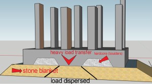
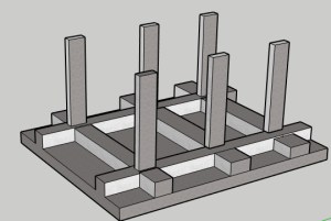
The figure represents a typical section of a micropile resting on a hard soil/ rock strata. The steel casing is restricted to the compressive strata and extends a bit into the hard strata for some anchorage. The surface area of contact between the ground and the concrete below the casing is known as bearing stratum.

The main components of micropiles are as follows

  • Reinforcement & casing
  • Grout

VIDEO : INSTALLATION OF MICROPILES

REINFORCEMENT USED IN MICROPILING

The reinforcement used in micropiles are divided into four categories

a) Standard rebar cage with centraliser
b) API pipe system 
c) Solid threaded rebars with or with out pipe casing
d) Hollow bar or Drill hollow bar system

a) STANDARD REBAR CAGE

REBAR CAGE

The rebar cage is the same as the cage used in conventional piling. Threaded couplers are used to join the bars together with staggered joints. A centraliser (as per fig) is used for positioning the rebar cage inside the bore.

b) API PIPE SYSTEM

API PIPE SYSTEM

API pipes (American petroleum Institute pipes ) are high-grade pipes having a diameter of 5 inches to 11 inches. These pipes are joined using high strength machined flush type joint threads. Both inside and outside of the API pipes shall be grouted with or without placing rebar. Centrally reinforcing type of solid threaded or standard rebar type (ref fig) can be used as rebar. API PIPE SYSTEMS are recommended for compression piles to maintain their lateral stability.

c) THREADED SOLID REBAR SYSTEM

Threaded solid rebar can be used alongside permanent/temporary casings and with API pipe as central reinforcements. Solid threaded Rebar constitutes a full threaded high strength bar that can be cut and jointed as per requirements. These bars not only functions to produce full tension and compression capacity but also enhances much-needed bonding with the grout.

d) HOLLOW THREADED BAR OR DRILL HOLLOW BAR SYSTEM

HOLLOW THREADED BAR SYSTEM

The hollow threaded rebar system is also known as a self-drilling hollow bar system. In this system, the hollow bar can function as a sacrificial drill bit. It gets converted to a central reinforcement. It can also be used to flush out the debris. This system can eliminate pre-drilling and frequent removal of pipes and drills. It can handle any condition relating to the installation of micropiles. When drilling is complete, an injection adapter (ref fig) performs the injection. It injects the cement mortar into the hollow core of the drill bit. This adapter is mounted with the drilling unit. The grout flushing simultaneously serves in stabilizing the borehole and filling the area.

DRILLING METHODS ADOPTED FOR MICRO PILES

The installation process of micro piles involves drilling or driving a bore through soils, rocks, overburden, etc. The most common methods adopted for drilling are:

Percussive Drilling used with a driving point/drill at the bottom of the permanent casing is defined as displacement method. When air is used as a flushing medium, it is defined as a non-displacement method.

Rotary drilling uses air or water as a flushing medium for removing the drilled materials from the drill hole. The air jet or water pumped through the drilling system exit at the drill bit end flushing out the cuttings.

GROUTING METHODS ADOPTED IN MICRO PILES

Grouts used for micropiles constitute a mixture of cement and water. Sand can also be added as per design requirements to reduce the overall cost. The micro piles are divided into four types based on the method of grouting

a) TYPE A MICROPILES

Type A micropiles use tremie grouting and through gravity head. The grouting is started from the bottom and follows a similar tremie grouting procedure followed in conventional piles.

b) TYPE B MICROPILES

TYPE B MICROPILES

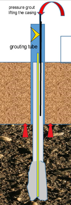
After performing the initial tremie grouting, a pressure grouting is followed simultaneously with the lifting of the casing from the bond zone. The second stage pressure grouting is done through a preinstalled tube. Second stage grouting serves in enhancing grout soil bonding. The grouting will be done up to the bearing stratum and can be extended to the full length of the pile if required.

c) TYPE C MICROPILES

In these types of piles, pressure grouting is followed by tremie grouting. On completion of pressure grouting, a global injection grouting is performed through a pre-installed sleeve port pipe. This grouting shall be done before the hardening of primary tremie grout.

d) TYPE D MICROPILES

This method is similar to Type C . In this method primary grout is done under pressure and after hardening secondary grout is done through installed sleeve ports. Packers are also provided for multiple injections.

METHODOLOGY OF MICRO PILES

Methodology of Micropiling

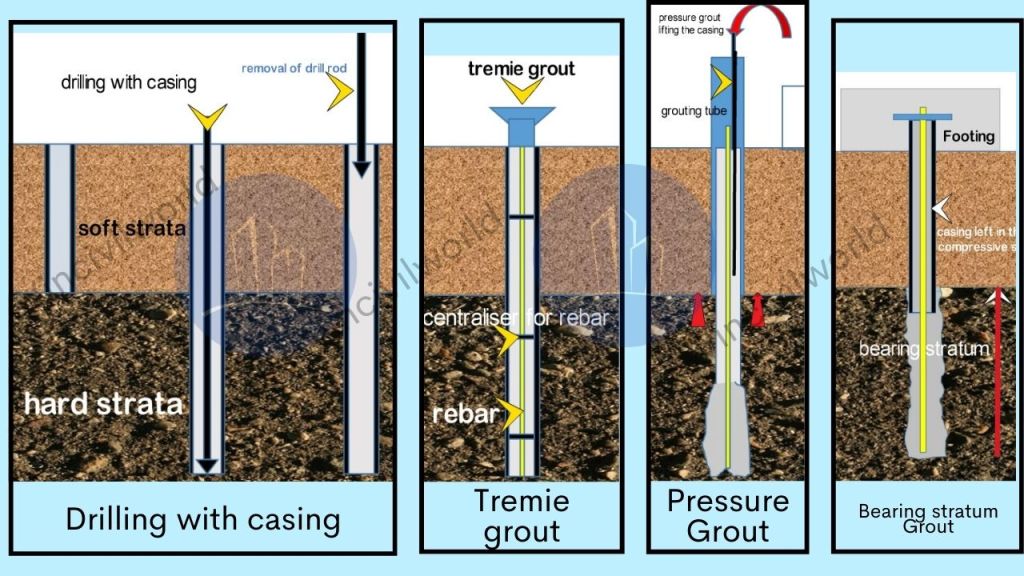
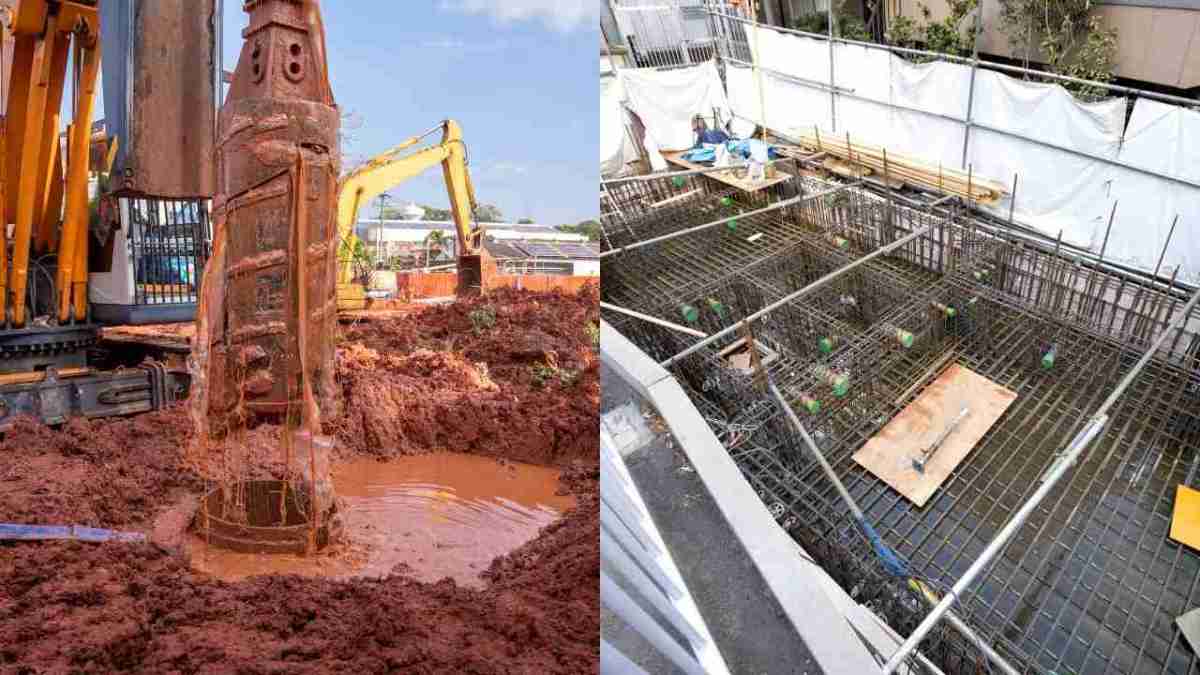
a) Drilling shall be commenced using a rotary rig or Rotary percussive drilling machine with casing attached to the drill bit and simultaneously pushed with the drill bit.

b) On reaching the founding level the drill bit is removed with casing left in the borehole.

c) Place reinforcement with centraliser in the borehole and followed by tremie grout with cement water mix.

d) The tremie grouting will be followed by a pressure grouting through preinstalled grouting tubes with simultaneously lifting of the casing.

e)The casing lifting to be done up to the compressive soil level with adequate bearing to the hard strata. (ref.fig) Complete pressure grouting of the bearing stratum area.

WHY MICRO PILE IS PREFERRED AGAINST CONVENTIONAL PILE?

a) Micropiles can be engaged in any challenging conditions involving soil and rock.

b) Micropiles can be customised and applied for difficult terrains and applications. The applications can either be in the form of new loads being added to an existing structure. They can also be used for arresting structural settlement. Additionally, they are for resisting uplift and dynamic loads. Micropiles are used for seismic retrofits or works involving underpinning and slope stabilisation.

b) Micropiles are used for rehabilitation projects as well as new constructions in difficult and access constraint terrains and settlement prone locations. For rehabilitation works in congested and low headroom height basements, micropiles prove to be a preferred option.

c) Micropiles penetrate any surface and can be installed even through an existing foundation making it one of the best possible solutions for foundation rehabilitation and strengthening works.

d) Micro piles can be used for slope stabilisation, embankment stabilisation, and other soil improvement and ground improvement works.

e)Micro piles can be used in areas where water table is high, urban back fills, areas having floating boulders or other difficult terrains that can’t even be accessed with a conventional pile.

d) Used extensively in the rehabilitation of monuments, old structures, sinking structures etc in all parts of the world.

Key Takeaways

  • Micropiles are an effective solution for difficult terrains and congested areas, making them ideal for urban projects.
  • Micropiling is a versatile method, allowing installation in any soil type and even through existing foundations.
  • Micropiles can bear both axial and lateral loads, supporting structures with capacities up to 300 tons.
  • Micropiling is widely used for foundation rehabilitation, structural retrofitting, and slope stabilization.
  • Micropiles provide reliable performance in areas with high water tables or floating boulders.
  • Micropiling offers minimal disruption to existing structures, making it suitable for projects in low-headroom or congested sites.

Conclusion

Micropiles are emerging as a perfect cost-effective option without any alternatives. Because of its design flexibility and wide range of applications micropiles are gradually entering into urban destiny.

Micropiles are becoming essential in modern construction due to their adaptability and strength. Micropiling offers a cost-effective solution for complex projects, including foundation rehabilitation, slope stabilization, and soil improvement. Their ability to penetrate various surfaces guarantees that micropiles are a preferred choice for challenging terrains. They can even penetrate through existing foundations, making them ideal for access-constrained environments. With advancements in micropiling technology, these piles provide superior load-bearing capacities. They minimize disruption. This makes them indispensable in both new constructions and retrofitting projects. As urbanization grows, micropiles will continue to play a vital role in foundation engineering.

MSE Retaining Walls – Components & advantages.

MSE Retaining Walls are also known as Mechanically Stabilised Earth (MSE) retaining walls. Commonly referred to as RE walls, they are a popular choice in modern construction due to their durability and cost-effectiveness. MSE retaining walls consist of layers of soil. The soil is reinforced with materials like geogrids or steel strips. This reinforcement provides essential stability against earth pressures. In this blog, we will explore the meaning of MSE walls, delve into their key components, and highlight their advantages. Additionally, we will examine real-world applications of MSE retaining walls and discuss important design considerations. By comparing RE walls with other retaining wall systems, you will gain a clear understanding of their features. This will help you decide their suitability for various construction projects.

MSE retaining walls means mechanically stabilised earth or reinforced earth. This is an earth retaining system where compacted granular soil is reinforced with horizontal layers of steel strips or geo-synthetic materials. This compacted earth is held together with thin facing elements made of Precast concrete, shotcrete or weld mesh reinforced panels. They are used extensively for constructing retaining walls, bridge abutments, highway wall systems, dykes, etc. MSE retaining walls cost almost half what a concrete structure would have cost for similar uses.

  1. What is an MSE Retaining Wall?
  2. Design basis of RE walls/MSE walls
  3. Components of a MSE retaining wall
    1. Reinforcement element
    2. Back fill materials
    3. Facing elements
    4. Drainage layer
    5. Jointing and filling materials
  4. Advantages of MSE walls
  5. Disadvantages of MSE retaining walls.
  6. Key Takeaways
  7. Conclusion

What is an MSE Retaining Wall?

An MSE retaining wall is also known as a Mechanically Stabilised Earth retaining wall. It is a structure designed to retain soil using layers of reinforced materials. MSE walls consist of compacted soil, reinforced with elements like geogrids or steel strips, providing stability against earth pressures. Often referred to as RE walls, these structures are popular due to their durability and cost-efficiency. To grasp the meaning of MSE walls, it’s essential to understand that the reinforcement materials bind the soil. This binding makes the wall robust and stable. MSE retaining walls are widely used in various construction projects, offering a reliable solution for earth retention.

Design basis of RE walls/MSE walls

When designing an MSE retaining wall, consider soil properties, such as bearing capacity and drainage, to ensure stability. Select appropriate reinforcement materials like geogrids or steel strips based on load requirements. Proper wall height and slope must be determined to manage earth pressures. Additionally, incorporate effective drainage systems to prevent water buildup behind the RE wall.

Components of a MSE retaining wall

An MSE retaining wall consists of several critical components that work together to provide stability and strength. These RE wall components include reinforced soil layers, facing panels, and drainage systems. The mechanically stabilised earth retaining wall relies on the interaction between the soil and reinforcement materials. Examples of these materials include geogrids or steel strips. This interaction helps to withstand earth pressures. Understanding these key elements is essential for designing a durable and effective MSE wall. The key components of a RE wall system is as follows.

a) Reinforcing element

b) Back fill materials

c) Fascia element

MSE walls or RE walls
MSE Walls or RE walls (Typical Section)
Typical section of MSE Retaining wall

Reinforcement element

The reinforcing elements of an MSE retaining wall are vital for its stability and strength. These elements typically include geogrids, steel strips, or geotextiles, which are embedded within the soil layers. The reinforcing materials work by binding the soil, creating a unified mass that resists earth pressures. In a mechanically stabilised earth retaining wall, these elements effectively distribute loads and prevent the wall from shifting or collapsing. The careful selection and installation of reinforcing elements are crucial for ensuring the long-term durability and performance of the RE wall.

The reinforcements are used to reinforce and provides the requisite tensile strength to hold the soil together. Two types of reinforcing elements are used in MSE walls. They are metallic and polymeric reinforcements. Metallic reinforcements (In-extensible) include Galvanised iron ribbed strips (50mm-100mm) or ladder strip arrangements.

Polymeric reinforcement (Extensible reinforcement) could be geo-grids or geo-textiles, which are preferred in corrosive environments. For any vertical and horizontal obstructions, reinforcements are bend at an angle, not more than 15 degrees.

Geo grids for reinforcing RE walls
Geo grids for RE walls

Appropriate connections hooks are embedded behind the fascia walls for the anchorage of geo-grids and metal reinforcements.

Back fill materials

For an MSE retaining wall, it is essential that the selected backfill materials are cohesionless. They must meet strict criteria, including gradation, plasticity, organic content, and electrochemical properties. These materials must be free-draining with minimal fine content. The soil friction angle for the MSE retaining wall must be verified by shear tests. The angle of interface friction between the compacted fill and the reinforcing element should be no less than 30 degrees, as specified by IS 13326 Part 1.

Fly ash Backfill

FLY ASH BACK FILL

Fly ash can be used as backfill for the RE wall, provided it adheres to applicable standards. The selected backfill should be placed parallel to the MSE retaining wall. It should start approximately three feet from the back of the wall panels. The backfill should be compacted in 6-inch lifts. Additionally, soil materials may be placed without reinforcement between the stabilised zone and the natural ground surface. This is known as retained backfill. It ensures the stability and effectiveness of the mechanically stabilised earth retaining wall.

Facing elements

Facing elements in an MSE retaining wall serve to retain filled materials. They prevent local slumping on steeply sloping faces. They also align with both structural and aesthetic requirements. These facings are commonly made of materials such as precast reinforced cement concrete, plain concrete hollow blocks, or similar components.

Facing elements
Facing Element of RE walls

Drainage layer


For the RE wall, it is essential to incorporate a suitable drainage system in the embankment area. This prevents water logging. A drainage layer, approximately 2-3 feet wide, is installed on the backside of the mechanically stabilised earth retaining wall. This layer uses free-draining material to facilitate proper water drainage from the reinforcement zones. This ensures the stability and effectiveness of the MSE retaining wall.

Drainage layer (image courtesy : Science direct)

Jointing and filling materials

Rubber or wooden bearing pads are used between horizontal joints of facing elements. This ensures there shall not be any concrete to concrete joints. The interior panel joints are sealed with geotextile filler cloth in the horizontal and vertical directions as shown in fig. This is done to ensure that no interior back fill materials sweep through the joints.

RUBBER PADS AND GEO TEXTILE LAYER

Advantages of MSE walls

MSE walls, or Mechanically Stabilised Earth walls, are favored for their economic and construction benefits. They enable rapid and efficient construction with minimal disruption to traffic and other services. MSE retaining walls offer a variety of materials and customization options, enhancing their popularity as earth-retaining systems. The fascia elements, backfill, and reinforcing system work together to form a gravity retaining structure. This structure relies on the self-weight of the reinforced soil mass. It resists lateral pressures from earth, service loads, seismic forces, and hydrostatic pressure. The flexibility and efficiency of RE walls make them a top choice in modern construction.

  • Heavy Load Capacity: Can support extremely heavy loads such as bridge abutment footings, crane loads, and service loads.
  • Seismic and Dynamic Resistance: Designed to resist seismic and dynamic forces, distributing bearing pressure over a wide area.
  • Faster Construction: Enables quicker construction compared to conventional retaining walls.
  • Minimal Site Preparation: Requires less site preparation and can be built in confined areas where other retaining walls are impractical.
  • No Additional Supports: No need for additional supports, finishes, or curing time.
  • Free Drainage: Granular backfill facilitates free drainage through panel joints, reducing hydrostatic pressure.
  • Lightweight and Precast Fascia: Fascia walls are lightweight, precast, and easily transported and lifted using simple equipment.
  • Customizable: Can be made to any height, customized for designs and logos, and adjusted to manage obstructions.
  • Versatile Construction: Can be tailored to any geometry, requiring no heavy machinery or specialized workers.
  • Durable Service Life: Provides a long service life even under extreme loading and complex conditions.

Disadvantages of MSE retaining walls.

  • MSE retaining walls require granular material in huge quantities. Areas where there is a scarcity of granular material the construction cost increase and make the structure uneconomical.
  • The corrosion or reinforcement and deterioration of geo-grids on exposed to sunlight has to be addressed. The reinforced component must be designed to withstand erosion and corrosion processes. These processes can highly deteriorate the mechanical behavior of the composite structure.
  • Proper drainage system should be provided.
  • The wall must obtain a minimum width in order to acquire adequate stability

Key Takeaways

  1. MSE Walls: Mechanically Stabilised Earth (MSE) retaining walls, also known as RE walls, offer durability and cost-efficiency.
  2. Components: Include reinforcing elements (geogrids, steel strips), backfill materials, facing elements, drainage layers, and jointing materials.
  3. Load Capacity: Capable of supporting heavy loads like bridge abutment footings and crane loads.
  4. Seismic Resistance: Designed to handle seismic and dynamic forces effectively.
  5. Construction Speed: Allows for rapid and efficient construction with minimal disruption.
  6. Customization: Flexible design options for various geometries and aesthetics.
  7. Free Drainage: Ensures effective water management to prevent hydrostatic pressure buildup.
  8. Durability: Long service life even under extreme conditions.

Conclusion

MSE retaining walls, or Mechanically Stabilised Earth walls, present a robust and economical solution for earth retention in modern construction. Their design incorporates various components, including reinforcing elements, backfill materials, and drainage systems, to ensure stability and functionality. MSE walls excel in supporting heavy loads, resisting seismic forces, and allowing rapid construction with minimal disruption. Customizable and versatile, they offer long-term durability and can be adapted to diverse project requirements. However, challenges such as the need for granular material and addressing potential reinforcement corrosion must be managed. Overall, MSE walls are a valuable option for efficient and effective retaining wall systems.

Driven piles – Features, Types and advantages

Driven piles support structures and transmit loads to underlying soil or rock, as they are a type of deep foundation used for this purpose. Contractors use driven piles, made of steel, concrete, or wood, to support structures and transmit loads to underlying soil or rock. They also call them displacement piles. The installation of driven piles involves driving them into the ground using impact hammers or vibratory drives until they reach a layer of rock or soil that can support the required loads.

If the soil is exceptionally dense, they may need to pre-drill to ensure the pile reaches the design depth. Construction projects commonly employ driven pile to provide stability and strength to the structure. Driven piles offer a cost-effective deep foundation solution and are commonly used to support buildings, tanks, towers, walls, and bridges.

  1. Why driven piles?
  2. Types of driven piles
    1. Steel Driven pile
    2. Pre-cast concrete Driven Piles
    3. Timber pile
    4. Composite driven pile
  3. Quality Control for Driven Piles
    1. Pile driving equipment for driven piles
    2. Pile inspection and testing
    3. Pile load testing for driven pile
    4. Pile driving records
  4. Advantages of driven piles
    1. High Capacity
    2. Ease of Installation of driven piles
    3. Cost-effective
    4. Minimal disturbance
    5. Versatility
  5. Disadvantages of driven piles
    1. Noise and vibration
    2. Limited depth
    3. Difficulty in driving through hard soil or rock
    4. Quality Control
    5. Limited environment suitability

Why driven piles?

Contractors often use driven piles, which are the most cost-effective deep foundation solution, to support buildings, tanks, towers, walls, and bridges. They are also suitable for embankments, retaining walls, bulkheads, anchorage structures, and cofferdams. Driven piles possess a high load-bearing capacity, durable, and contractors can install them quickly and effectively in various soil conditions. Engineers frequently use them in places with inadequate soil, where conventional shallow foundations would not be strong enough to sustain buildings.

In addition, contractors can install driven piles to support compression, tension, or lateral loads, with specifications determined by the structure’s needs, budget, and soil conditions, making them very versatile.

Related posts from vincivilworld

Types of driven piles

Driven piles are broadly classified as follows

  • Steel Driven pile
  • Precast Concrete Driven pile
  • Timber pile
  • Composite driven pile

Steel Driven pile

Steel-driven piles support major structures such as buildings, bridges, roads, and industrial facilities in construction. Construction workers push them into the earth using specialized tools like hydraulic hammers or pile drivers until they reach a predetermined depth or a firm layer of rock or soil. Steel-driven piles are steel beams with broad flanges on both ends.

Steel Driven Pile

Steel-driven piles are typically made of high-strength steel with a round or square cross-section. They come in various lengths and widths and can be installed vertically or at an angle to meet foundation design requirements. An impact hammer is used to press the pile into the soil by delivering a forceful blow. For shorter depths, steel screw piles are supported by a cast iron helix and powered by rotary motors.

Because of their durability, strength, and capacity to support enormous loads, the steel-driven pile is a common choice for deep foundations. Steel-driven piles are a cost-effective and quick solution for many construction projects. However, their applicability will depend on factors such as soil characteristics, anticipated loads, and local construction building codes and regulations.

Pre-cast concrete Driven Piles

Precast concrete pile manufacturers deploy these piles in construction to support structures built on weak or compressible soils. They prefabricate these piles in a factory or casting yard before transporting them to the construction site. Based on the project’s unique needs, they can construct precast concrete piles in a vast range of dimensions, forms, and configurations. High-strength concrete, reinforced with steel rebar, is used to make these piles. They often use a vibratory hammer or hydraulic hammer to drive the piles into the earth until they reach the required depth or a solid layer of soil or rock.

Precast Concrete Driven Piles

Piles come in a variety of shapes, such as square, octagonal, cylindrical, or sheet. Percussion-driven piles are used in situations where bored piles would be ineffective due to running water or excessively loose soils. They have a load range of 300-1,200 kN and a maximum reach of 30 m. Precast concrete piles are constructed with great accuracy and quality control in a controlled environment, resulting in a consistent and uniform product that satisfies design requirements. They are durable and can withstand adverse weather conditions such as seawater or chemical exposure. Precast concrete piles can also be installed quickly and effectively, saving time.

  • Precast concrete piles are quick to install.
  • They can be used in various soil conditions.
  • Using precast concrete piles saves time and money in construction.
  • Precast concrete piles are durable and reliable.
  • They have high-quality control standards.
  • Precast concrete piles are a popular choice for deep foundation construction.

Timber pile

Timber-driven piles are used in construction to create a stable foundation for structures in weak or compressible soils. Contractors use hammers or pile drivers to create cylindrical or square wood piles from premium softwood species. This type of pile is particularly effective in areas with high water tables where other types of piles may not work as well. Timber-driven piles provide a stable foundation for structures in weak or compressible soils. This is achieved by hammering wooden piles into the ground, which compresses the wood and displaces the surrounding soil. The resulting tight fit helps to support the weight of the structure. Timber-driven piles have the advantages of being inexpensive and simple to install. Nonetheless, they may be susceptible to rot and pest infestation.

timber driven piles
timber-driven-pile

Composite driven pile

Engineers commonly use composite piles made of a combination of two or more materials, such as concrete, steel, or timber, when soil conditions require a combination of strength and flexibility. An example of a composite pile is a concrete pile with a steel section, as shown in the figure.

Contractors use composite-driven piles consisting of a steel tube filled with concrete and reinforced with steel rebar because they can withstand heavy loads. They use in various construction projects, such as bridges, high-rise buildings, and marine structures. The steel tube provides structural support and protects the concrete from damage during installation, while the concrete and rebar provide additional strength and stability. Contractors can install composite piles using hydraulic hammers or vibratory drivers to reach depths of up to 60 meters. Due to their durability and corrosion resistance, composite piles are ideal for use in harsh environments.

composite pile

Quality Control for Driven Piles

The construction of driven piles requires high-quality materials and adherence to standards such as BS 8004:2015 and EC standards. It’s crucial to maintain the pile’s shape and avoid damage during installation and inspect them beforehand for quality assurance. The maximum load a pile can carry depends on soil or rock strata properties, pile dimensions and material, and installation method. Engineers perform load testing on representative samples to determine capacity and use monitoring instruments like inclinometers and settlement gauges to ensure the pile’s sufficient support. Effective quality control and testing are crucial for the safe and reliable performance of driven piles in construction projects.

driven piles

During installation, it is crucial to maintain the shape of driven piles and ensure they are not damaged by the installation of subsequent piles.

Quality control of driven piles is an important aspect of ensuring the stability, safety, and longevity of structures that rely on them for support. Here are some of the common quality control measures used for the driven piles.

Pile driving equipment for driven piles

To make sure that piles are installed correctly, trained personnel are required to maintain, calibrate, and operate pile driving equipment properly. Regular inspections are necessary to detect any damage or wear in the equipment, and repairs or replacements must be made promptly.

Pile inspection and testing

Inspect the piles for defects or damage before driving them into the ground. To ensure that the piles have been installed correctly and meet the specified requirements, non-destructive testing methods such as sonic testing or integrity testing should be used to test the piles after installation.

Pile load testing for driven pile

pile load test

One can conduct load testing of a sample of piles to ensure that they can support the required loads. This involves applying a controlled load to the pile and measuring the resulting deformation, which one can compare to the design specifications to ensure that the piles are safe and reliable.

Pile driving records

One should keep detailed records of the pile driving process, including the number of blows or vibrations required to drive the pile to the required depth, the penetration rate, and any other relevant information. These records are essential to monitor the quality of the installation and identify any issues that may arise during the construction process.

Regular inspections and testing are essential to identifying any issues early in the construction process and enabling prompt corrective action.

Advantages of driven piles

The main advantages are

  • Piles can be pre-fabricated off-site which allows for efficient installation once on-site.

High Capacity

Piles are driven deep into soil or rock. This provides high load-bearing capacity. It’s suitable for supporting heavy structures like buildings, bridges, and marine structures. The process increases the effective length of the pile, resulting in high capacity.

Ease of Installation of driven piles

Compared to other pile types like drilled shafts, the installation of a driven pile is quick and efficient. The installation process involves driving the piles into the ground using an impact hammer or a vibratory driver. This requires minimal excavation and soil removal.

Cost-effective

Other types of foundation systems can often be more expensive than driven piles, particularly when the soil conditions are favourable. The cost-effectiveness of driven piles is due to their relatively simple installation process and the availability of pre-manufactured piles, which can reduce the time and cost required for pile installation.

Minimal disturbance

The installation process of driven piles minimizes the disturbance to the surrounding area, making them suitable for use in urban or environmentally sensitive areas. The piles are driven into the ground, which reduces the amount of soil disturbance and the need for excavation.

Versatility

Driven piles are suitable for a variety of soil conditions, including soft soils, hard soils, and rock layers. They can also be made of different materials such as steel, concrete, and timber, providing a wide range of design options.

  • When driven into the ground, piles displace and compact the soil, resulting in increased bearing capacity. In contrast, other types of deep foundations may require soil removal, which can cause subsidence and structural problems.
  • Installation usually produces little spoil for removal and disposal.

Overall, driven piles offer several advantages in terms of high capacity, speed of installation, cost-effectiveness, minimal disturbance, and versatility, making them a popular choice for foundation systems in many construction projects.

However, the use of driven piles also has some disadvantages, including their relatively high cost compared to shallow foundations, the noise and vibration associated with their installation, and the potential for damage to nearby structures or utilities. Therefore, the selection of driven piles as a foundation type depends on a variety of factors, including soil conditions, load requirements, and site-specific constraints.

Disadvantages of driven piles

In the design and construction process, it is important to consider the disadvantages of driven piles, despite their many advantages. Some of the main disadvantages of driven piles are:

Noise and vibration

The installation of driven piles can generate high levels of noise and vibration. This can be a concern for nearby residents and sensitive structures. Pile driving can cause damage to nearby structures, particularly those with shallow foundations.

Limited depth

Other foundation types may be necessary if the capacity or depth required cannot be achieved with driven piles. This is because of the limitations imposed by soil or rock conditions and the driving equipment’s capacity.

Difficulty in driving through hard soil or rock

Driving piles in hard soil or rock layers can be difficult and time-consuming, which can lead to higher installation costs. Overcoming the hardness of the soil or rock may also require the use of specialized driving equipment or techniques.

Quality Control

The installation of a driven pile requires critical quality control. Poor installation can cause issues such as pile damage, pile movement, or insufficient load capacity. To ensure that the piles are installed correctly and meet the required standards, regular inspection, and testing are required. Moreover, monitoring is necessary during pile installation.

Limited environment suitability

Driven piles may have limited suitability in environmentally sensitive areas. This includes wetlands or areas with a high water table. This is due to the potential soil disturbance caused by the driving process. Moreover, the use of chemicals for the preservation or treatment of piles can have negative impacts on the environment. It is important to consider these factors and explore alternative foundation options in such areas.

Types of Raft Foundations – Advantages and features

Types of Raft Foundation are chosen based on a variety of criteria, including bearing capacity, applicable loads, site conditions, cost-effectiveness, etc. A raft foundation is a continuous slab resting on the soil and covering the entire area of the proposed structure. This is one of the most commonly used types of foundation in construction. Raft foundation types are classified according to their application.

But what is a raft foundation? It is a large concrete slab that spreads the load of the building over a wide area. This helps prevent uneven settling. There are various types of raft foundations, each with its unique features. Understanding raft foundation types is crucial for selecting the right one for your project. Raft foundations are versatile, cost-effective, and efficient. This blog will explore the different types of raft foundations, their advantages, and features, helping you make an informed decision for your construction needs.

  1. What is a raft foundation?
  2. Types of raft foundation – Principle
    1. Soil Stress Calculation
  3. Why choose Raft Foundations?
  4. Types of Raft foundations
  5. Types of raft foundations: Solid slab raft foundation
    1. Flat raft mat foundation
    2. Wide-toe raft
    3. Blanket raft foundation
    4. Slip plane rafts
  6. Slab beam-type raft foundation
  7. Piled raft foundation
  8. Cellular raft foundation
  9. Balancing or floating raft foundation
  10. Advantages of the Raft foundation
  11. Disadvantages of raft foundations
  12. Key Takeaways
  13. Conclusion

What is a raft foundation?

A raft foundation/mat foundation is a solid slab that is placed at a specific depth and spreads across the entire structure. Raft foundations have shear walls and columns to transfer loads from the structure to the ground. These foundations are typically used when the soil’s bearing capacity is low and it becomes challenging for individual footings to handle the loads. The raft foundation aids in transferring the entire load of the structure to a larger area. This type of foundation helps prevent uneven settling.

There are different types of raft foundations, each designed for specific needs. Knowing the various raft foundation types is essential for choosing the right one for your project. Raft foundations are cost-effective and versatile, making them a popular choice in construction. By understanding what a raft foundation is, you can make informed decisions for your building’s foundation needs.

Types of Raft foundation

Types of Raft foundations – Youtube video

Video of Raft foundation- Types and Advantages

Types of raft foundations – Related articles from vincivilworld

Types of raft foundation – Principle

The raft foundation distributes the total loads from the structure over the entire area of the structure. When compared to other types of foundations used in civil construction, they can reduce soil stress. Raft foundations differ from other foundations due to this mechanism of stress distribution.

Soil Stress Calculation

stress = total load coming on the structure + self-weight of raft/ Area of raft foundation

Consider a total load is 300 T and a foundation size

Size : 20 m x 10 m

Stress on the soil = 300/200 = 1.5 t/sqm

The same structure supported with 8 individual footing

Size : 2m x 2 m

Total area = 8 x 4 = 32 sqm

Stress on soil = 300/32 = 9.375 t/sqm

This shows that same load we are getting stresses of 1.5 T/sqm for raft and 9.375 T/sqm for individual foundations.

As the contact area of the raft is more the load is distributed over a larger area and hence stresses coming on the soil are very less.

Why choose Raft Foundations?

Raft foundations are typically preferred over other foundations when one of the following situations arises.

  • Individual footing design and pile foundation construction can be expensive when the soil’s bearing capacity is very low.
  • When the soil’s bearing capacity is less and it is essential to minimise stresses that have been induced into the soil.
  • The columns, shear walls, and so on are so close to each other that individual footings may overlap.
  • Any other type of foundation may cover more than 50% of the total ground area beneath the structure.
  • When a possibility of unequal settlement exists.
  • Preferred for complex equipment foundations.
  • Used when the proposed structure includes basements.

Raft foundations are appropriate for basement buildings where the foundation slabs will be subjected to direct live loads depending on the utility of the building. Raft foundations are a better choice because excavations can be finished with the aid of light excavators in areas with poor soil conditions and limited access to heavy excavation equipment.

Types of Raft foundations

The types of raft foundations are chosen based on a variety of factors, including bearing capacity, applications, cost-effectiveness, and so forth. Raft foundations are broadly categorized as follows.

  • Solid Slab Raft Foundation
  • Slab Beam Raft Foundation
  • Piled Raft foundation
  • Cellular Raft Foundation
  • Balancing or Floating raft foundation

Types of raft foundations: Solid slab raft foundation

In a Solid slab raft foundation, the columns and walls are equally spaced, and the load distribution is also equal. Because they are designed as slabs of uniform thickness, these raft foundations are known as solid slab raft foundations. These foundations are reinforced with a bottom layer and a top layer.

Solid slab raft foundations are classified into four types.

  • Flat raft mat foundation
  • Wide toe raft
  • Blanket raft foundation
  • Slip plane rafts

Flat raft mat foundation

Flat raft mats are used for small buildings with uniform column spacing and a foundation that covers the entire structure. These foundations have bottom and top reinforcements.

Types of raft foundation - Flat raft mat
Types of raft foundation – Flat raft mat

Wide-toe raft

A wide-toe type of raft foundation is used when the structure needs to be economical. A full-size solid slab mat foundation may not be required to support the structure’s loads. In that case, a heavily reinforced toe is provided on both sides, as shown in the figure, to handle the loads.

Types of raft foundation - Wide-toe raft
Wide-toe raft

Blanket raft foundation

blanket raft foundation

Blanket rafts are used when the surface has unequal settlements or nonuniform strata. In this type of situation, stone blankets will be laid as shown in the figure on a compacted surface. The stone blankets and raft shoes help to distribute the load on the structure.

Slip plane rafts

The slip plane raft foundation has a fully compacted sand bed beneath the raft. To facilitate the transfer of loads, the sand bed size should be slightly larger than the raft size. The sides of the foundation can be filled with any compressible material.

Slip plane raft foundation

Slab beam-type raft foundation

slip plane raft foundation

Slab beam-type raft foundations are used when the loads are unequally distributed and the foundation is prone to distortions. Beams included with the slabs serve as stiffeners. The raft is reinforced with two layers of mesh, one at the bottom and one at the top. The beams can offer additional stiffness and guard against distortion.

Piled raft foundation

piled raft foundation

Rafts are supported by pile foundations in this type of Mat Foundation, as illustrated in the figure. When the loads on the structure are extremely high, the soil bearing capacity is very low, and the water table is very high, these foundations are used. Piled raft foundations are ideal for high-rise buildings, and heavy industrial structures such as high-rise RCC chimneys, silos, and storage tanks that are typically supported by a single foundation element. Due to their high cost, they are not commonly used in residential applications. Piled raft foundations eliminate the need to design a very heavy raft foundation or a very conservative pile foundation with larger depths.

Instead, they opt for a combination of an optimised raft foundation and a pile foundation capable to share the loads. Over the pile foundation, the raft foundation floats. Typically used in structures such as chimneys, silos, bunkers, and overhead storage tanks where even minor soil settlement may cause the structure to fail.

Cellular raft foundation

cellular raft foundation

A cellular raft is made up of two-way foundation beams with a solid slab on the ground below and a suspended slab on top. The upper and lower slabs are joined by intermediate beams, transforming the foundation into an I-beam structure.

For covering the top slab, precast soffits can be used. The top slab is cast using precast soffits or other types of permanent formwork or sacrificial formwork, and it is filled with lightweight infill blocks.

Typically used in areas subjected to heavy mining activity and with poor soil-bearing capacities. The foundations must withstand massive bending moments. They are the preferred option in these cases. Cellular rafts are used when removing overburdens resulting in increased bearing capacity. Cellular rafts can be used to control soil uplift pressure.

Balancing or floating raft foundation

Balancing rafts or floating foundations are used in areas where the soil’s bearing capacity is very low and the soil settlements must be kept within an acceptable range.

The floating foundation operates on the principle that the total weight of the soil and water removed from the excavated area must equal the weight of the proposed structure.

Advantages of the Raft foundation

completed raft foundation.
  • Raft foundations are a safe and cost-effective alternative to other shallow and deep foundation types.
  • Raft foundations are preferred in areas with low soil bearing capacity, uneven settlement, and mixed soil types. The load-bearing capacity of these foundations is achieved by distributing stresses over a larger area.
  • In densely populated urban areas, access to the sites is frequently restricted, making it impossible to mobilise heavy equipment for foundation construction using other techniques. Raft foundations can be built with very little equipment because of their low heights.
  • Raft foundations, when compared to other isolated foundations, provide a much-needed option for designers in terms of limiting settlement limits within the codal provisions.
  • When deciding on settlement values, the designers have the option to choose higher values when compared to standard foundations. The raft foundation prevents uneven settlement.
  • Raft foundations are a very flexible design option that can be customised to the soil conditions and workability.
  • The execution of a raft foundation is simpler than that of individual footings. This, in turn, can speed up the project.

Disadvantages of raft foundations

Most of the time, raft design is not considered economically when the soil conditions are extremely poor. Complex raft foundations consume a large amount of concrete and steel and necessitate precise professional/technical supervision and workmanship. As a result, the structure is more expensive than any other alternative foundation. The soil beneath the foundation, especially near the edges, must be preserved.

Key Takeaways

Understanding the types of raft foundations is crucial for making informed decisions in construction. Raft foundations are continuous slabs of concrete that distribute loads across a wide area, preventing uneven settling and providing stability in poor soil conditions. They are versatile and cost-effective, making them popular in various construction projects. Different types of raft foundations, such as solid slab, slab beam, piled, and cellular rafts, each offer unique advantages tailored to specific structural and soil requirements. By choosing the appropriate raft foundation type, you can ensure the stability and durability of your building while optimizing construction costs and efficiency.

Conclusion

Raft foundations are an essential element in modern construction, particularly in areas with challenging soil conditions. They provide a robust solution for distributing loads evenly, preventing differential settling, and ensuring the structural integrity of buildings. Understanding the various types of raft foundations, from solid slab to piled and cellular designs, allows for tailored applications that meet specific project needs. While they offer numerous advantages, including cost-effectiveness and versatility, it is important to consider site-specific conditions and professional expertise in their design and implementation. By doing so, you can achieve a durable, stable foundation that supports your building efficiently and effectively.

Raft foundation types and features

Raft foundation is a continuous slab that completely covers the entire site of the proposed structure and rests on the soil. Depending on the applications and design loads, there are various raft foundation types. The choice of raft foundation type is influenced by a number of variables, including bearing capacity, loads, site circumstances, etc.

Raft foundation – Definition

A raft foundation or mat foundation is a solid slab that is put at a predetermined depth and covers the entire structure. Raft foundations have shear walls and columns for distributing loads to the ground. These foundations are appropriate for places with low bearing capacity, wherein individual footings struggle to traverse the stresses. Moreover, the raft foundation aids in the transfer of the structure’s total load to a larger area. In comparison to other forms of foundations used in civil construction, raft foundations can minimize soil stress levels. This mechanism of stress distribution distinguishes raft foundations from other types of foundations.

Raft foundation
Raft foundation

Determining soil stress

Stress = total load acting on the structure + raft self weight / raft foundation area

Assume a total load of 300 T and a foundation size of 20 m x 10 m

Soil stress = 300/200 = 1.5 t/sqm

The same structure is supported by 8 separate footings. 2 x 2 mtr 8 x 4 = 32 sqm total space

Soil stress = 300/32 = 9.375 t/sqm

This demonstrates that for the same weight, we get stresses of 1.5 T/sqm for the raft and 9.375 T/sqm for the individual foundations.

Because the raft’s contact area is greater, the load is distributed across a larger region, resulting in less stress on the soil.

Raft foundations – Where to use them?

When the following circumstances exist, these foundations are typically favoured over other foundation types.

  • When the bearing capacity of the soil is extremely low, building individual footings and executing deep foundations such as pile foundations becomes prohibitively expensive.
  • When soil stresses must be reduced since the soil’s bearing capacity is lower.
  • The columns, shear walls, and so on are so close to each other that individual footings may overlap.
  • Any other type of foundation may cover more than 50% of the total ground area beneath the structure.
  • When there is a possibility of unequal settlement.
  • Likewise, Raft foundations are Preferred for complex equipment foundations.
  • When the proposed structure has basements, raft foundations are preferred

For basement constructions where the foundation slabs would be subjected to direct live loads raft foundations are preferred based on the utility of the structure. Raft foundations are also a preferable option for sites where soil conditions are poor and access to major excavation machinery is limited, wherein raft foundations excavations can be accomplished with the help of light excavators.

Types of raft foundations

Raft foundations are classified into several types based on soil conditions, structure functionality, and so on. The following are some of the most popular raft foundation types used in civil construction.

  • Solid Slab Raft foundation/ Flat plate type foundations
  • Slab beam Raft foundation
  • Piled Raft Foundation
  • Cellular raft foundation
  • Balancing or floating raft foundation

Solid Slab Raft Foundations

Flat plate raft foundations are made up of a reinforced concrete slab of uniform thickness covering the entire bearing area. In this type of raft foundation, the columns and walls are equally spaced, and the load distribution is also equal. 

These raft foundations are known as solid slab raft foundations because they are designed as slabs with uniform thickness. This is ideal when the columns are evenly spaced and have equal and minor weights. Steel mesh reinforcement is offered in both directions of the slab. Two meshes are reinforced at the top and bottom of the slab to balance upward and downward bending stresses. 

Solid slab raft foundation

The following are the various types of solid slab raft foundations that are commonly used based on design requirements.

  • Thickened flat plate type raft foundation
  • Wide toe raft foundations
  • Blanket rafts
  • Slip plane raft foundations

Thickened flat plate type raft foundations

When the column loads are extremely heavy, the flat plate type foundation is inadequate. To make it suitable, the slab thickness must be increased. The substantial loads on the column cause negative bending moments and diagonal shear in the slab. A full-size solid slab mat base is not required to negotiate the design loads. To compensate,  a section of the slab beneath the column should be thickened. The placement of a pedestal beneath the column without increasing the slab thickness also assists in receiving heavy loads. 

Wide toe raft foundations

A wide toe raft is used when the ground conditions require an unusually thick concrete slab to provide the necessary load support, which would be quite expensive. For negotiating the design loads,  a full-size solid slab mat base is not necessary. A substantially reinforced toe is provided on both sides of the structure, as illustrated in the image, for economizing the structure.

Wide toe raft foundation

Blanket raft foundations

When the construction site comprises small areas of weaker soil or diverse soil types with unequal settlements or nonuniform strata, a blanket raft may be the best option. Before laying the raft foundation, the surface is compacted and stone blankets are spread in layers on the prepared ground, as shown in the figure. However, despite the build’s footprint’s flaws, the raft foundation and stone blanket work together to provide even load support.

Blanket rafts
Blanket rafts

Slip plane raft foundations

A preliminary layer of sand is put across a slightly larger surface than the required raft foundation for slip plane rafts, and the gap around the raft is filled with packed material. A thoroughly compacted sand bed supports this type of foundation beneath the raft.   The foundation’s sides can be filled with any compressible material.

Slip plane raft foundation
Slip plane

Slab beam type raft foundations

When the loads are unequally distributed, there seems to be a lot of space between the columns, and the foundation is susceptible to distortions, slab beam raft foundations are preferred. Beams are set in perpendicular directions in this scenario, and they are all connected by a raft slab. The beams incorporated with the slab act as stiffeners and prevent distortions. Columns are precisely located on the intersections of raft foundation beams, as illustrated in the figure. The raft’s reinforcement consists of two mesh layers, one at the bottom and one at the top.

slab beam raft foundation
slab beam raft

Piled raft foundation

Pile foundations are used to support the slab in the case of piled raft foundations. When the loads on the structure are exceedingly high, the soil bearing capacity is very low, and the water table is exceptionally high, this method is commonly used. Piled raft foundations are ideal for high-rise buildings and large industrial structures such as high-rise RCC chimneys, silos, and storage tanks that are typically supported by a single foundation element. Because of their exorbitant costs, these foundations are not generally used in residential applications. Designing a very heavy raft foundation or a  very conservative pile foundation with greater depths is avoided by using a piled raft. Instead, they opt for a hybrid of an optimal raft foundation and a pile foundation capable of supporting the structural loads.

piled raft foundation
Piled raft foundation

Cellular raft foundation

A cellular raft is made up of two-way foundation beams with a solid slab lying on the ground below and a suspended slab on top. Between the upper and lower slabs, intermediate beams are provided. The intermediate beam is responsible for transforming the entire structure into an I Beam. The top slab is cast using precast soffits or various types of permanent formwork, sacrificial formwork, or lightweight infill blocks. Cellular raft foundations are often used in areas with significant mining activity and poor soil carrying capacity, where the foundations must withstand huge bending moments. These types of raft foundations are used when eliminating overburdens resulting in greater bearing capacity. Moreover, cellular rafts can be used to control soil uplift pressure.

Cellular raft foundation

Balancing raft or Floating Raft Foundation

Balancing rafts or floating foundations are deployed in situations where the soil bearing capacity is very low and the soil settlements must be kept within an acceptable range. 

The floating foundation operates on the idea that the total weight of the earth and water removed from the excavated area must equal the weight of the planned structure.

This process involves huge earthwork excavation. Dewatering systems like well point systems have to be provided when the water table is very high. Likewise, Sheet piles are to be installed for weak soils or soils that may collapse. To protect the nearby structures from any defects due to scoring of soil, temporary retaining walls etc. have to be organized before starting excavation and some of these activities have to go in tandem with excavation. This type of structure is not economical and requires very minute technical supervision.

These foundation types are used for building structures in highly dense areas following all safety precautions to avoid any damage to the nearby structures.

Floating rafts are preferred for building with multiple levels of underground car parking facilities. However, for more details about floating rafts, you can go through our detailed article Balancing rafts or floating raft foundations

Advantages of Raft Foundations

  • Raft foundations offer a safe and cost-effective alternative to conventional shallow and deep foundation types.
  • Preferable in areas with low soil bearing capacity, uneven settlement, and the presence of mixed soil types. By distributing stresses across a larger area, these foundations are able to achieve load-bearing capacity.
  • Used in congested metropolitan locations where access to sites is limited and heavy machinery mobilisation for foundation construction using conventional deep foundations, such as pile foundations, is not feasible. 
  • Raft foundations can be built using very light machinery due to their low heights.
  • Raft foundations offer designers a much-needed alternative to conventional isolated foundations for limiting the settlement restrictions within the codal provisions.
  • When compared to regular foundations, the designers have the option of choosing larger settlement values during the design process in the case of raft foundations. Moreover this in turn can avoid an unequal settlement.
  • Got flexible design alternatives that can be customized as per soil conditions and workability.
  • Comparatively speaking, the execution is simpler than individual footings. This, in turn, can accelerate the project schedule.

Disadvantages of raft foundations

  • In extremely poor soil conditions, raft foundations are not cost-effective. 
  • Complex raft foundations demand careful professional/technical supervision and workmanship and consume a  substantial amount of concrete, and steel. As a result, the structure is more expensive than any other alternative foundation.
  • The soil beneath the foundation, particularly around the margins, must be protected. Edge erosion is common in raft foundations.
  • When the soil conditions are extremely poor, pile foundations are more cost-effective than raft foundations.
  • Raft foundations occasionally need further strengthening, which raises the overall cost.
  • Compared to other foundations, skilled labour is needed for raft foundations.
  • When the mat or raft foundation is under the concentrated(point) load, further care should be taken.

Crib retaining walls, Bin retaining walls & Gabion Walls

Retaining walls are rigid walls used for supporting soil laterally so that it can be retained at different levels on the two sides. The soil got a natural angle of repose and when it exceeds the range a retaining wall structure has to be provided.

They are vertical or near vertical structures constructed to hold soil between two terrains when the slope exceeds the natural one. The slope can be vertical or steep or much above the range of angle of repose.

Also read : Retaining walls – All Types, Materials, features and uses

In this article we are mentioning about some special type of retaining walls

Gravity retaining walls are made of stone, bricks, concrete or any other heavy material.  Gravity walls are made with or without mortar They are designed to counter the earth pressure by their self weight. Following are the special types of gravity retaining walls.

a) Crib retaining wall

b) Bin retaining wall

c) Gabion retaining wall

Crib Retaining walls

Crib retaining wall or crib lock retaining wall is one of the oldest types of retaining wall. They consist of cribs or cells made of timber, concrete, and plastic/fibres. The cribs or interlock areas are filled with free-draining materials or earth back-fill, eliminating the hydro-static pressure and enabling a free escape of water.

Most common materials used for crib wall construction is 

  • Timber crib retaining walls
  • Precast crib retaining walls

Timber crib retaining walls

Timber crib walls use timber to form the cells of the crib. The cells are filled with free-draining stone materials for maintaining the mass of the wall. Water drainage can happen freely through the cribs. The timber sections are interlocked to make the walls.
They can also be planted with trees to create a natural appearance. These types of walls are ok up to a height of 5-6 mtrs and mostly used for landscape walls etc.

Timber crib retaining walls

Precast concrete crib retaining walls

This system consists of a precast concrete header and stretcher units. They are erected to form precast crib retaining walls.
Precast concrete cribs are the cheapest form of earth-retaining systems and are used for landscaping structures, plant terraces, and other works with heights around 10- 20 mtr with proper professional design.
They do not require any skilled labour to do the erection. Trees or shrubs are planted to give natural and excellent looks. Crib walls are erected for small curves and are considered a very flexible material.

Precast Concrete Crib retaining walls

Bin retaining walls

Steel bin walls are made from corrugated steel sheets and are usually bolted together and then filled with crushed rock or other free-draining material. They are mostly used for bank erosion protection, holding encroaching slopes, breakwaters, etc. They can resist unforeseen ground movements that may cause failure to other types of retaining walls.

Gabion Retaining walls

Gabion retaining wall systems are one of the oldest forms of gravity wall. Gabion walls are manufactured by factory fabricating a galvanised hexagonal wire mesh of varying diameters into box cages. These box cages are site filled with locally available stones and fully closed and laid in a pattern as per design. They are used in areas where the foundation conditions are not favourable for adopting any other retaining structures. The concept of a gabion wall is to increase the shear capacity of rock by providing the box cages. They can accommodate substantial ground movements without failures. Gabion boxes are free-draining structures that can reduce hydro-static pressure drastically.

Gabion Retaining walls

The main advantage of these types of systems is that they do not need an exclusive foundation structure. Gabion walls are installed directly over the surface in specified patterns according to design requirements.
The mesh is PVC protected or coated with special coatings to protect from rusting in areas subjected to continuous water flow.
These walls provided a Good visual appeal of the product and the satisfying rock finish look.
Gabion walls are erected mainly for soil stabilisation behind the wall. They can also act as a cover wall. The gabion boxes are stacked in layers with a proper design. They are a very economical alternative for concrete retaining walls and rock anchors for soil stabilisation works and slope protection works.

Also read : MSE retaining walls or Mechanically stabilised Earth walls