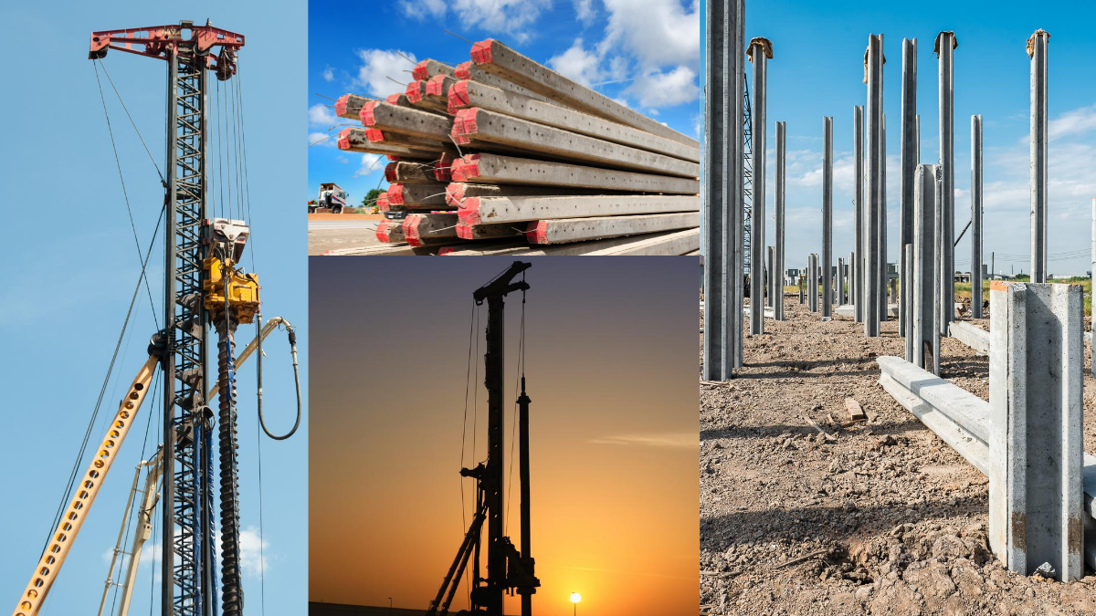
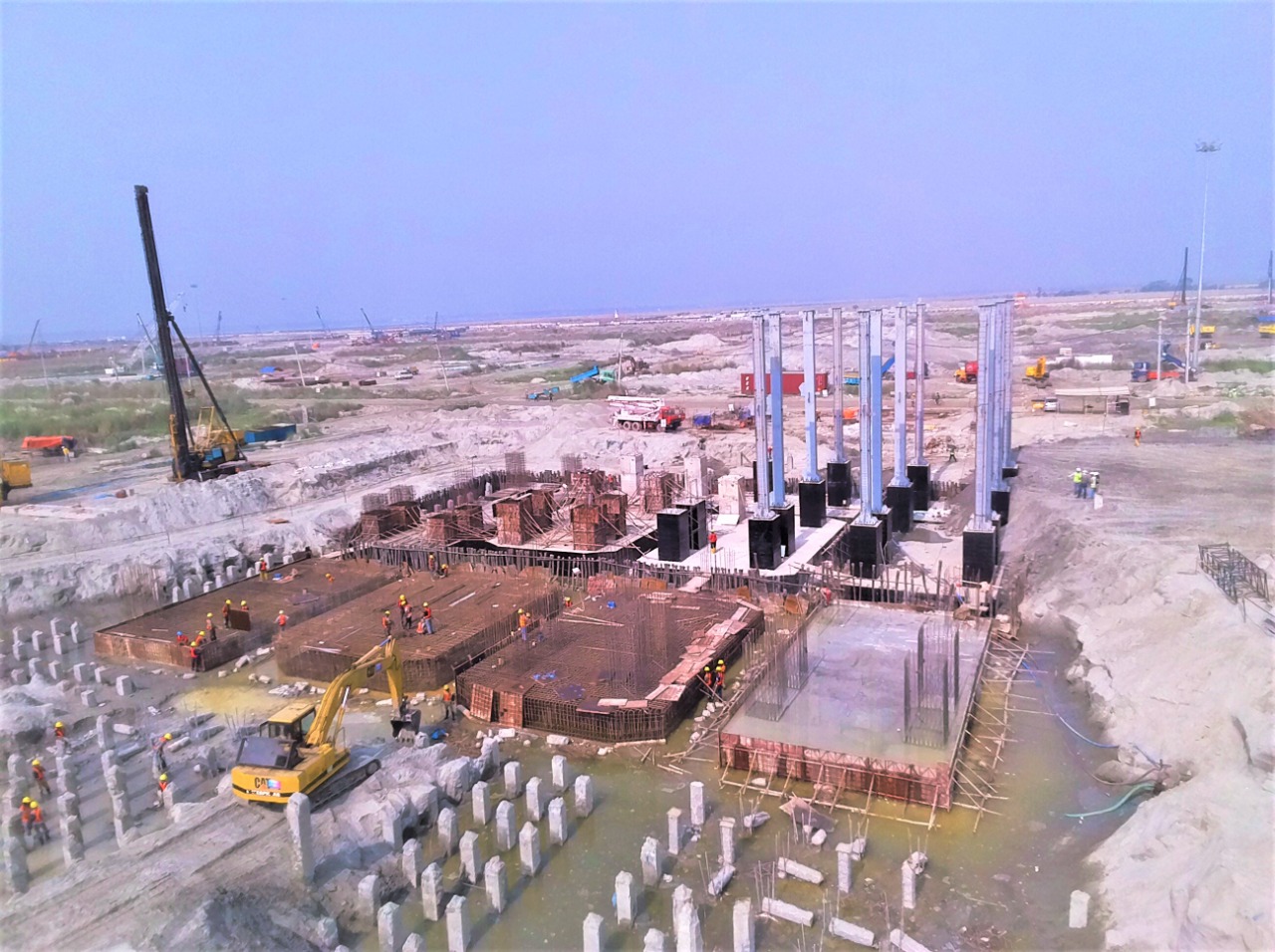
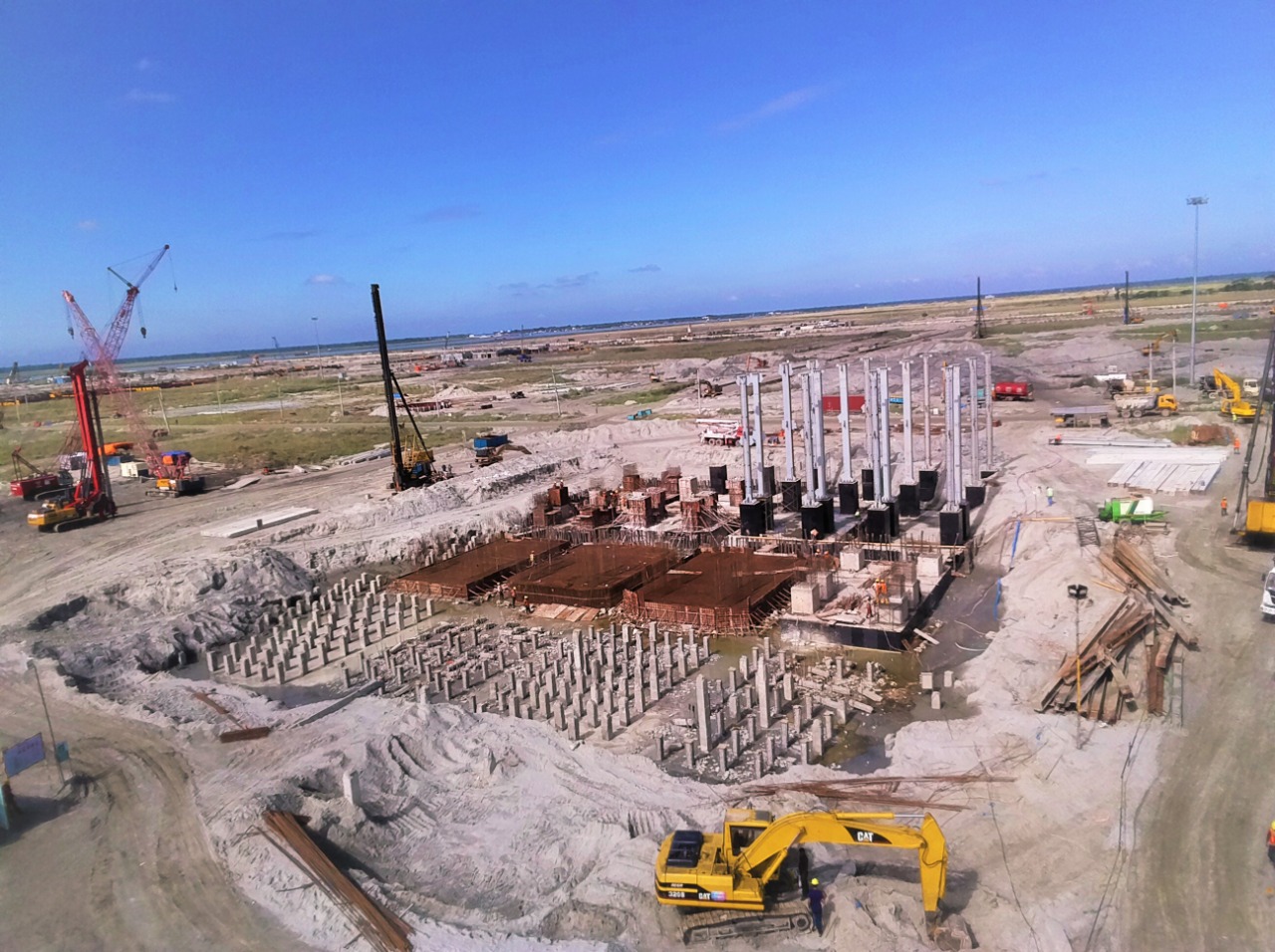
Pile Foundation
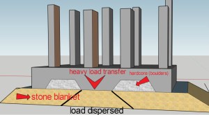
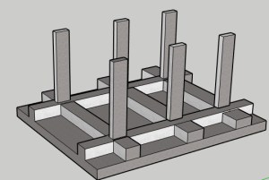
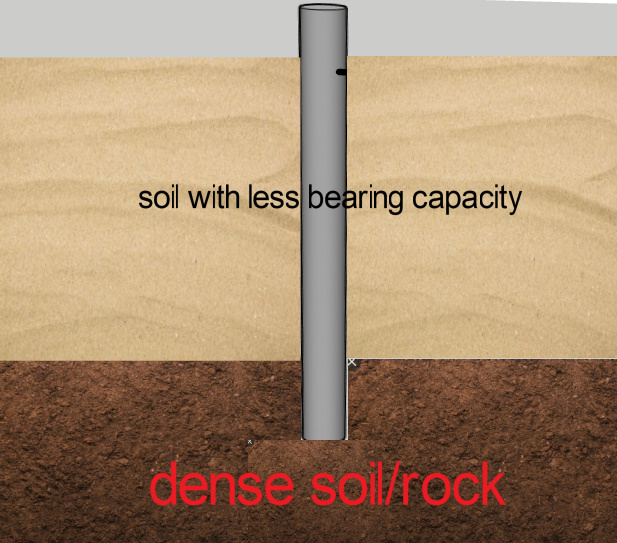
Pile foundations are long, slender members. They can be concrete, steel, or any other material. These foundations transfer the loads of a structure when the subsoil lacks the bearing capacity. The pile foundations transfer the load vertically through the less denser top layer to a high denser soil/rock layer which can negotiate the loads without failure.
What is a pile foundation? A pile foundation is a deep foundation system used to support structures. It transfers loads through weak or compressible soil layers to more stable soil or rock layers below. Pile foundations are essential in areas where surface soils cannot bear the load of the structure. There are various pile foundation types, primarily categorized into friction piles and end bearing piles. Friction piles transfer load through skin friction along their length. End bearing piles transfer load through the pile tip bearing on a strong layer of soil or rock. Understanding what are pile foundations and their types helps engineers select the appropriate system for ensuring stability and support for different types of construction projects.
In this article, we will explore pile foundation types, including friction and end bearing piles, their applications, and benefits.
- Pile Foundation
- CHOICE OF PILE FOUNDATION
- CLASSIFICATION OF PILE FOUNDATIONS BASED ON FUNCTION/LOAD TRANSFER
- CLASSIFICATION BASED ON CONSTRUCTION METHODS
- CLASSIFICATION BASED ON MATERIALS
- Key Takeaways
- Conclusion
CHOICE OF PILE FOUNDATION
Pile foundations are preferred in areas with weak or compressible soil, where surface conditions cannot support the required structural loads.
- When the groundwater table is very high, other types of open foundations require huge dewatering. This is done by the well point or deep bore well method. It turns out to be quite expensive and not feasible.
- When heavy and non uniform distribution of loads from the superstructure which causes unequal settlements in open foundations.
- The low soil bearing capacity makes the design of shallow foundations very conservative. Site conditions also contribute to making it uneconomical.
- When the settlement of soil exceeds the permissible limit while designing a shallow foundation.
- Soil washing or scouring away from the foundation sides can occur. This happen due to the presence of any underground systems. A nearby river or canal can also cause this issue.
- When any type of soil excavation is impossible due to very poor soil strata .
CLASSIFICATION OF PILE FOUNDATIONS BASED ON FUNCTION/LOAD TRANSFER
- a) END BEARING PILES
- b) FRICTION PILES
- c) FRICTION CUM BEARING PILES
- d) BATTER PILE
- e) ANCHOR PILE
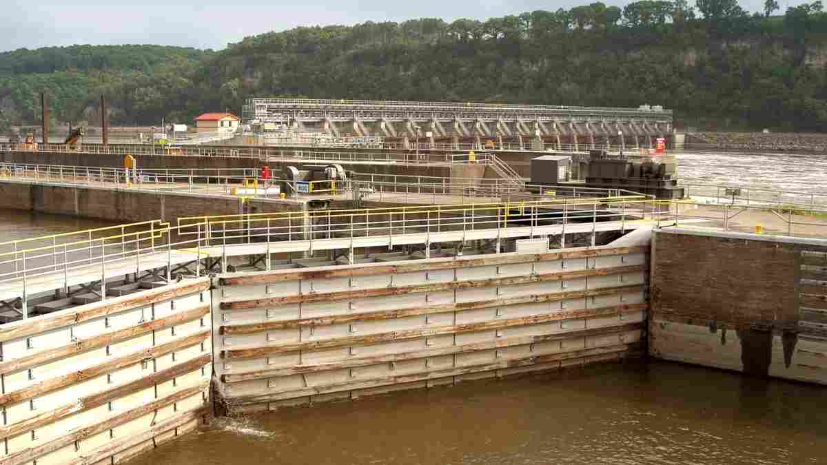
- f) SHEET PILE

END BEARING PILES
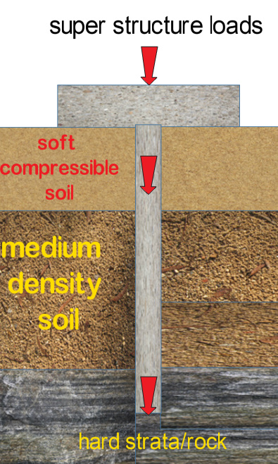
A bearing pile is a slender member/ column which transmits vertically all loads coming from the super structure. It is transmitted through a lower density weak layer of soil to a denser strata much below the ground which is capable of negotiating the loads. The pile acts as a column member which transfers the loads to the bearing strata.
FRICTION PILES

This type of pile is used when a suitable strata for negotiating the loads are available at a very deeper area and taking piles to that depth is not economically feasible. Friction piles utilises the shear stresses/skin friction along the surface of the pile. The load transfer is done through the frictional resistance between the pile surface and the surrounding soil. The total surface area of the pile is involved in the load transfer process. Greater the embedded length more is the load carrying capacity of the pile. Load carrying capacity of pile is directly proportional to its length.
FRICTION CUM END BEARING PILES
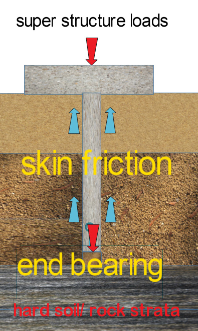
These type of piles negotiate the loads through the combined action of end bearing and skin friction . In this case the piles can be terminated in a medium or stiff clay rather than resting on a hard strata. These types of piles are preferred and considered economical hence it is the most commonly used type of pile foundation.
CLASSIFICATION BASED ON CONSTRUCTION METHODS
The execution of piling is done in two methods
- a) DRIVEN OR DISPLACEMENT METHOD
- b) BORED OR REPLACEMENT METHOD
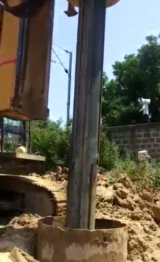
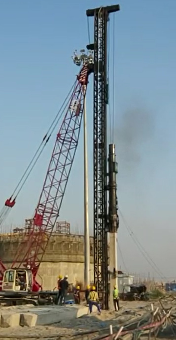
DRIVEN OR DISPLACEMENT PILES
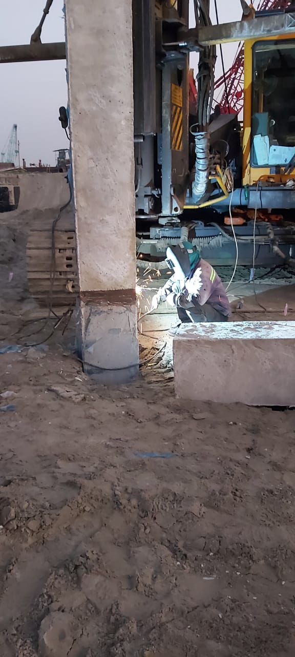
In this method the piles are driven into the soil/sand which causes lateral displacement of soil and hence it is called displacement piles. Displacement piles are basically designed to be installed without removal of soil. Special equipment are used to drive the piles and displace soil laterally. Depending on situations these types of piles are preferred over bored piles.
BORED OR REPLACEMENT PILES
In this type of foundation bores of required diameter is made and are filled using RCC. It can be a cased or uncased types depending on the collapsible nature of the soil.
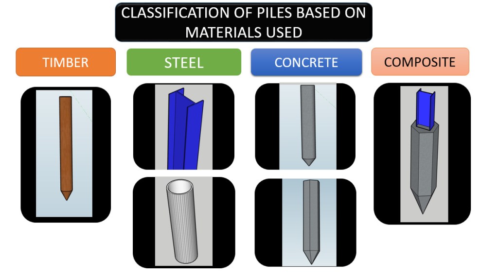
CLASSIFICATION BASED ON MATERIALS
- a) TIMBER PILES
- b) STEEL
- c) CONCRETE
- d) COMPOSITE PILES
TIMBER PILES
The timber piles are sharpened logs obtained from trees like sal, teak, deodar, babul, etc. These piles are used in water and can resist sea water better than other piles. These piles are basically friction piles and are driven into the ground. The timber pile length varies from 20-25 mtr and is designed for a load of around 20 t.
Advantages of timber piles
a) Timber piles are available in varied sizes and is cheaper than any other type of piles.
b) It is easy to install and can be cut into any size as per the requirements.
c) Timber piles is more reliable in marine works.
d) Timber piles doesn’t decay even when submerged in water for a prolonged time.
Disadvantages of timber piles
a) It is difficult to get Straight and long timber piles.
b) Timber piles may not pass through all strata. It is difficult to drive piles in hard and dense strata.
c) Timber piles can be used only as friction piles and not as end bearing piles. Splicing of a timber pile is difficult.
d) As a prevention against possible decay timber piles has to be treated with preservatives.
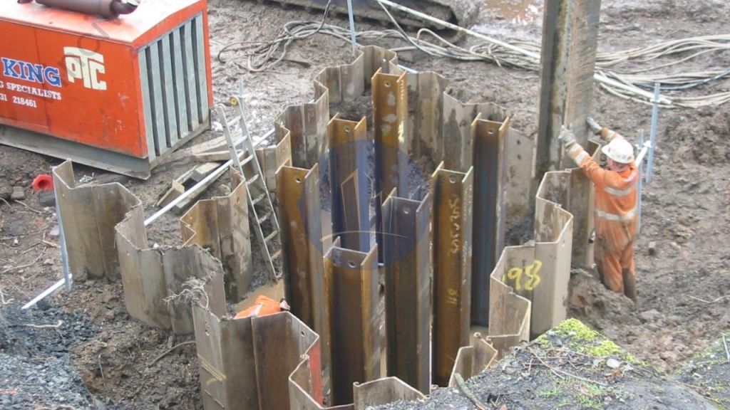
STEEL PILES
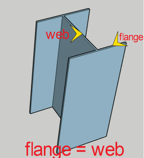
Steel piles may be of H-section or hollow pipe (Fig) . They can be used for an optimum length of 20-40 mtr. The size can be upto 600 mm dia pipes and can also done using HP sections having the same flange and web width as shown in the fig. These piles are mostly designed as end bearing piles . These piles are driven as open ended or closed ended . The closed ended pile shall be filled with concrete.
Advantages of steel piles
Steel piles are very easy to install. Due to their less cross sectional area it can penetrate through any type of soil layer with minimal soil displacement.
Splicing of steel piles are easy and it can go to any depth compared to other type of piles.
The penetrating properties of steel piles helps to go deep and hence can carry more loads than other pile types.
Disadvantages of steel piles
Steel piles are corrosion prone and has to be coated with anticorossive coatings before driving.
While encountered with a hard strata the H sections tends to deform or sometimes the verticality of pile is lost while driving.
The steel piles are very expensive.
CONCRETE PILES
Concrete is the most common material used for construction of piles due to their design flexibility and ease of execution. Concrete piles are normally used in the following categories.
DIFFERENT TYPES OF CONCRETE PILES

- a) PRECAST CONCRETE PILE
- b) PRESTRESSED CONCRETE PILE
- c) CAST IN SITU
- d) COMPOSITE PILE
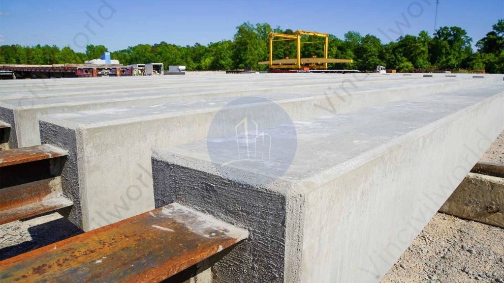
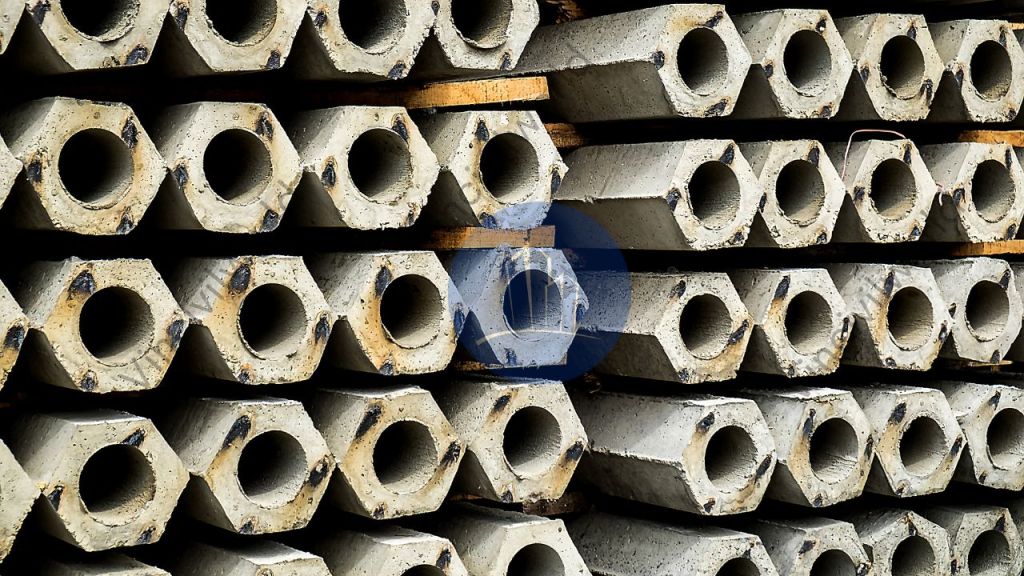
PRECAST CONCRETE PILE
Precast pile uses conventional RCC. Piles are casted in a fabrication yard and conveyed to the location for erection . Precast pile are either square or round . The rectangle or square shaped piles are casted in a horizontal fabrication bed and round pile is casted vertically. Precast piles are designed to take care of the loads/stresses developing while lifting, conveying and driving.
PRESTRESSED CONCRETE PILE
Prestressed concrete pile is preferred when the sizes of the precast piles go beyond a certain limit. Prestressing can optimise the pile size drastically making it very easy to lift ,convey and erect. Prestressing is done by stretching the tendons and pouring concrete keeping the tendons in a stretched position. Once the concrete develops full strength the tendons are released . The released tendons in the process of regaining its shape induces compressive stresses in the member.
Prestressing convert the pile into a high load carrying member which can resisting the stresses. due to the impact loads generated on driving, the uplift forces and the combined moments. These piles can be used for an optimum design depth of 25-35 mtrs.
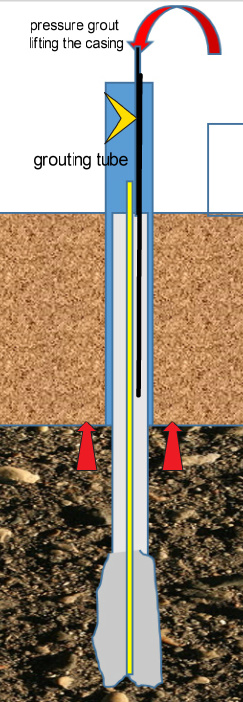
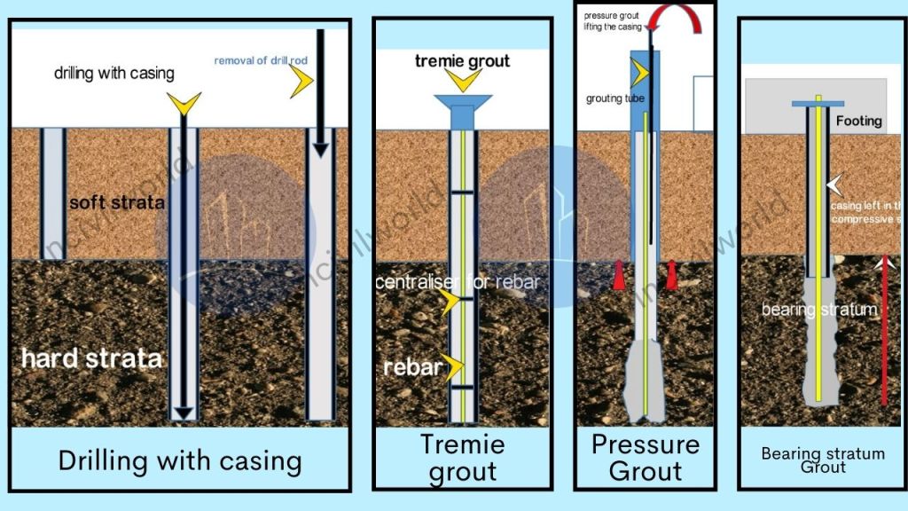
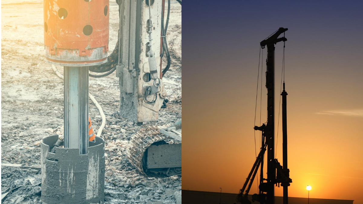
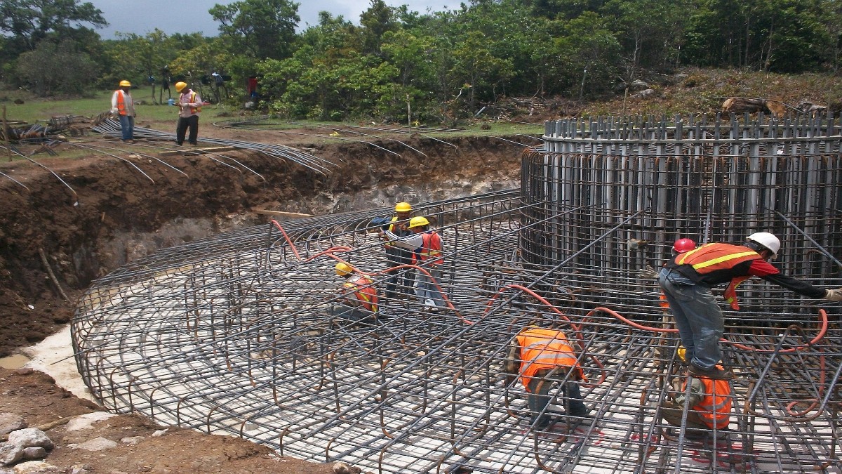
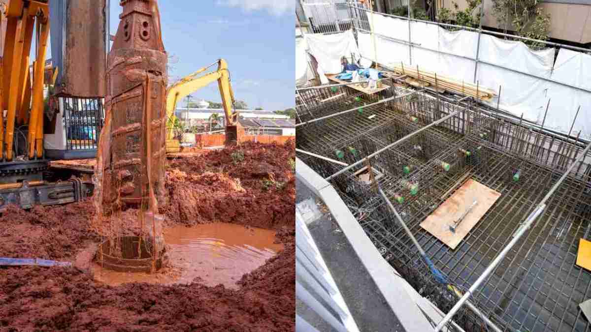
CAST IN SITU CONCRETE PILES
Cast in situ piles are constructed by drilling a bore hole to the required level and filling it with Reinforced cement concrete. The bore hole can be formed by excavating ground with the help of a rotary drilling equipment or hydraulic rigs. Casings are driven into the bores locations before drilling . The casing will be removed gradually during concreting process or sometimes left in the bore as a permanent casing
Advantages of Cast-in-Place Concrete Piles
Cast in situ piles are very flexible and the process of execution is easier compared to driven piles and other type of piles.
The reinforcement cages are light weight and easy to handle. The rebar cages are fabricated with the help of simple and conventional tools.
No chances of breakage during installation stage .
If there is some issue with the pile that prompts the customer to abandon, additional substitution piles can be done.
Disadvantages of Cast-in-situ Concrete Piles
a) Installation requires careful supervision and quality control. Because once a pile gets abandoned executing a replacement pile is expensive and time consuming.
b) Cast in situ piles generate a lot of pile muck ( mix of bentonite and soil). The pile muck has to be removed and disposed as per environmental policy . The pile head chipping also generates lot of concrete waste which has to be disposed.
c) Requires space for movement of Rigs, cranes, stocking of materials and bentonite tank.
d) Under water flow can collapse the piles.
e) Concrete quality cannot be visualized. Hence health assessment tests like pile integrity test are to be conducted to confirm the pile integrity.
COMPOSITE PILES
A composite pile is made up of two or more sections of different materials or different pile types. The top portion shall be casted using concrete and the other portions shall be of steel or timber. These type of piles are used in special applications
Key Takeaways
- Pile Foundation Definition: Pile foundations are deep foundation systems used where surface soils are weak or compressible.
- Types of Piles: Two primary types are friction piles and end bearing piles. These piles are used to transfer loads through weak soil layers to more stable ones.
- Friction Piles: Transfer loads using skin friction along the pile’s length. They are suitable for deeper layers where strong strata are not easily reachable.
- End Bearing Piles: Transfer loads through the pile tip resting on strong soil or rock layers.
- Construction Methods: Pile foundations can be driven (displacement) or bored (replacement) depending on site conditions.
- Material Variants: Piles can be made from materials like timber, steel, or concrete, each with distinct advantages and limitations.
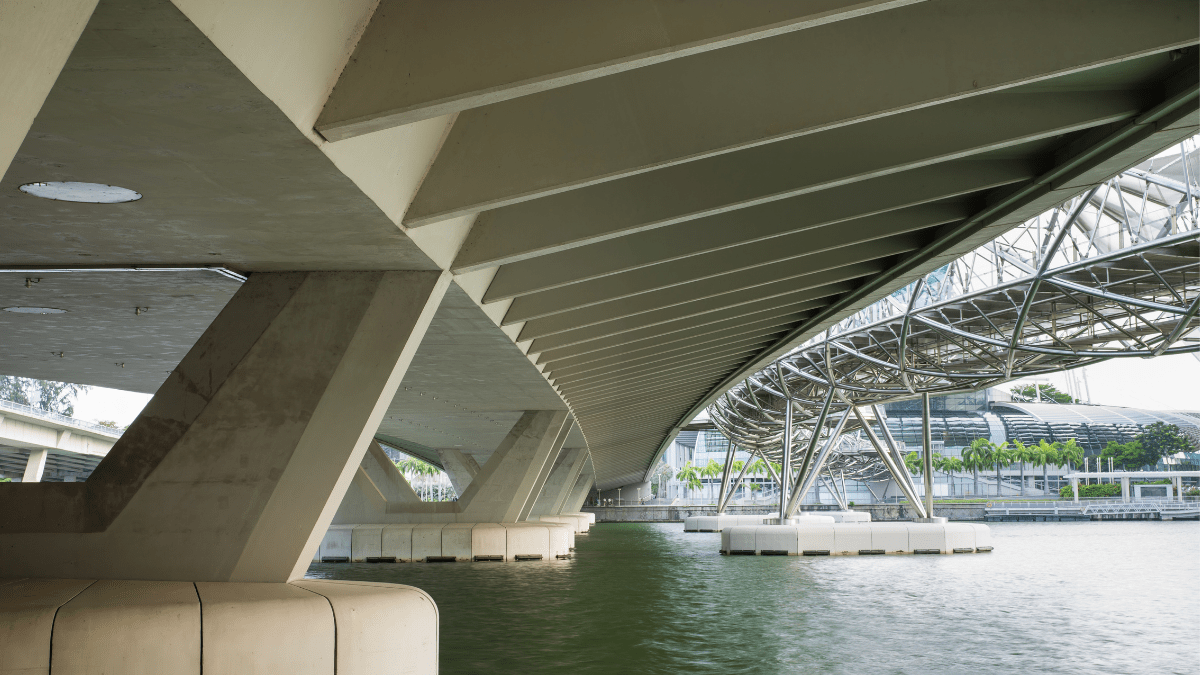
Conclusion
Pile foundations are essential in modern construction. They provide reliable support where traditional shallow foundations cannot suffice due to weak or compressible soils. Understanding what is pile foundation and the differences between friction and end bearing piles helps engineers select the appropriate foundation type for specific projects. Driven or bored methods of installation can vary based on soil conditions, while materials like timber, steel, and concrete offer unique advantages. For example, concrete piles, especially cast-in-place or prestressed, are popular due to their flexibility and high load capacity. As a versatile foundation system, pile foundations ensure structural stability in challenging geotechnical environments, making them an indispensable choice for construction in weak soil conditions.