Aqueduct || Cross Drainage Works || Types and functions

Aqueduct is a cross drainage structure constructed to channel water from the rivers or stream to the distribution points. But modern engineering aqueduct is a cross drainage system that constitutes pipes, ditches, canals, tunnels, and supporting structures. These are constructed or laid to convey water from a source to the main distribution points. Aqueducts/cross drainage systems play and important role in maintaining the strategic flow between drainage water with canal water.

Cross drainage works is a modern day aqueduct. It is constructed to intercept a drain crossing or canal crossing. This prevents the water from mixing between these sources.

  1. Significance of Aqueducts and Cross drainage works
  2. Cross drainage system/Aqueduct – Need
  3. Aqueduct /Drainage type selection
  4. Types of Cross drainage works
    1. Type 1 – irrigation canal passes over the drainage
      1. Aqueduct
        1. Advantages of Aqueduct
      2. Syphon Aqueduct
    2. Type-2- Drainage passes over the irrigation canal
      1. Super Passage
      2. Canal Syphon
    3. Type 3 – Drainage and canal intersection each other of the same level
      1. Level Crossing
      2. Inlet and Outlets or Canal Inlet
  5. Key Takeaways
  6. Conclusion

Significance of Aqueducts and Cross drainage works

Aqueducts and cross drainage works play vital roles in managing water flow and maintaining infrastructure integrity. An aqueduct was historically used to transport water across valleys and uneven terrain. It has evolved into essential modern structures. These include syphon aqueducts designed to overcome challenging topography. Cross drainage works, including culverts, bridges, and siphons, ensure efficient water management by directing flow under roads and other obstacles. This blog will explore the various types of aqueducts. It will also discuss cross drainage systems and their functions. Additionally, it will highlight their significance in infrastructure development. We’ll delve into syphon aqueducts and their unique role in hydraulic engineering, highlighting their applications.

Cross drainage system/Aqueduct – Need

The cross drainage system is an expensive structure and has to be avoided. But there may be situations when the following conditions are encountered and the cross drainage is to be provided.

  • The cross drainage design can minimise the discharge velocity at the intersection point.
  • The ideal condition of aligning the canal without intersecting the drainage is not possible. The increase in the length makes construction difficult. 
  • A canal is set between head work and the main watershed. The water supply is not intervened by providing cross drainage work.
A historic stone aqueduct featuring multiple arches, set against a backdrop of a cityscape with modern buildings and hills in the distance.
View of an ancient aqueduct showcasing its iconic arches and structure, illustrating its importance in water management.

Must Read : Components of a Dam – 12 components explained

Must Read : Methods of Irrigation – 3 methods fully explained

Aqueduct /Drainage type selection

The primary factors for drainage works are relative bed levels, water levels, canal and drainage discharge. However, the choice of drainage types can be summarised based on

  • Alignment of the canal
  • Discharge from canal and drainage 
  • Capacity of Foundation 
  • Economic condition
  • Canal head loss
  • The water level of canal and drainage

Must Read : Controlled Flooding – 6 types – Free Flooding – Basin Flooding

Types of Cross drainage works

Cross drainage works are essential in water management. They ensure that irrigation canals and drainage channels can intersect without disrupting their functions. These structures prevent flooding, erosion, and waterlogging, maintaining the efficiency of both irrigation and drainage systems. Cross drainage works are broadly classified into three types. The classification is based on how the canal and drainage interact at the crossing point. Each type is designed to handle specific hydraulic challenges, ensuring smooth water flow across different terrains.

The cross drainage works are broadly classified into three types as shown below

a )Type 1 – irrigation canal passes over the drainage

  • Aqueduct
  • Syphon aqueduct

b) Type 2 – Drainage passes over the irrigation canal

  • Super passage
  • Canal syphon

c) Type 3 – Drainage and canal intersection each other of the same level

  • Level crossing
  • Inlet and Outlet

Type 1 – irrigation canal passes over the drainage

The structures coming in this category are

  • Aqueduct
  • Siphon Aqueduct

Aqueduct

An aqueduct is a cross drainage work. It is used when the bed level of the canal is above the drainage bed level. This is shown in the figure. The canal water flows from upstream to downstream freely under gravity. The canal trough is rested on a series of piers.

An aqueduct is a structure that carries an irrigation canal over a drainage channel. It is a key component in cross drainage works, ensuring the canal water flows uninterrupted above the drainage. This design prevents the drainage water from mixing with the canal, avoiding contamination and erosion. Aqueducts are vital in areas with uneven terrain, where traditional water management methods fail. They efficiently transport water across valleys and other obstacles. Aqueducts are among the primary types of cross drainage works. This category includes syphon aqueducts, which use enclosed channels to manage higher hydraulic pressures.

Diagram illustrating an aqueduct, featuring an inspection road, RCC rectangular trough, and both Full Supply Level (FSL) and High Flood Level (HFL) indicators.
Diagram illustrating an aqueduct with key features including inspection road, RCC rectangular trough, and water levels marked as Full Supply Level (FSL) and High Flood Level (HFL).

The canal water level is known as full supply level or FSL. Drainage water level is referred to as High Flood Level or HFL. This level is below the canal bed level.

The shape of the canal is a rectangular trough or trapezoidal trough. It is similar to a bridge, railway, or roadway. 

Advantages of Aqueduct
  • They are utilized for irrigational purposes and water supply.
  • It is held over piers, made of stone or reinforced concrete.
  • The freeboard of 0.5 m is implemented.
  • The section of the trough is determined by FSL and the height of the section is determined by HFL. 
  • An inspection road is given on the sides of the trough. 

Syphon Aqueduct

A syphon aqueduct is a type of cross drainage work. The irrigation canal flows over a drainage channel through an enclosed conduit. This design uses siphonic action to maintain water flow, even across steep gradients. In the syphon aqueduct, the canal bed level is below the full supply level. The water flows from upstream to downstream through aqueduct barrels following siphonic action. A sloping apron is provided on both sides to depress the canal level.

The enclosed structure prevents water contamination and erosion, making it ideal for challenging terrains. Unlike open aqueducts, syphon aqueducts handle higher hydraulic pressures effectively. They ensure uninterrupted canal water flow while safely directing drainage beneath. Syphon aqueducts are a crucial part of cross drainage works. They provide a reliable solution in areas where traditional aqueducts not suffice.

In a syphon aqueduct, canal water is carried above the drainage. The high flood level (HFL) of drainage is above the canal trough. The drainage water flows under syphonic action and there is no presence of atmospheric pressure in the natural drain.

Syphonic aqueducts are more often constructed and better preferred than simple Aqueduct, though costlier.

Diagram illustrating a syphon aqueduct, featuring labeled components like inspection road, FSL (full supply level), HFL (high flood level), cut-off wall, and concrete floor, alongside water flow directions.
Diagram illustrating the structure of a syphon aqueduct, showcasing the relationship between canal water flow and drainage levels.
  • The section of the trough is determined by the canal water level.
  • Cut off walls are provided at both ends. 
  • The sloping apron is built by using stone or cement concrete. 
  • The bottom of the siphon aqueduct is impervious.
  • The atmospheric pressure is not taken into account. 
  • They are more prefered than an aqueduct.
  • They are expensive.

Type-2- Drainage passes over the irrigation canal

  • Super passage
  • Canal Siphon

Super Passage

The super passage is type of cross drainage work and a hydraulic structure where drainage passes over the irrigation canal. They contradict the aqueduct. The water from the drainage flows through the troughs under gravity and atmospheric pressure. 

This design allows the canal to pass beneath the drainage without interference. The structure prevents the canal from flooding and ensures effective water management. Unlike an aqueduct, the super passage prioritizes the drainage flow, allowing it to cross over the canal. It is essential in areas where drainage water must remain separate from canal water.

Diagram illustrating a super passage structure showing the banks of a canal, the full supply level (FSL), and the high flood level (HFL) with stream flow indicated.
Diagram illustrating a super passage, showing how drainage passes over an irrigation canal.

The drainage trough is constructed at the road level. These are preferred when drain discharge is less compared to canal discharge. An inspection road cannot be constructed on the sides of the trough. Thus they are not available for an open investigation.

A separate bridge is equipped for the roadway. Also, a ramp is given at the doorway. It is supported by piers. 

  • To avoid scouring, boulder pitching is given at the bed and banking. 
  • The section of the drainage is concluded by the high flood level.
  • For safety, a freeboard of 1.5 m is given.
  • The concrete foundation is provided, But the depth of the foundation is determined by the availability of soil. 

Canal Syphon

Canal syphon is implemented when the drainage passes over the canal. The canal water flows under syphonic action and no atmospheric pressure is considered. Since the canal water is under drainage, the exclusion of sediments and silts is impossible. 

Diagram illustrating a canal syphon, showing water flow through the structure with banks of the canal marked, indicating Full Supply Level (FSL) and High Flood Level (HFL).
Diagram illustrating the Canal Syphon, showing the relationship between the canal’s Full Supply Level (FSL) and the High Flood Level (HFL) of the drainage, emphasizing water flow direction.

The inspection road cannot be provided, a separate bridge is constructed for the roadway. 

  • The selection of trough is designed based on the HFL.
  • A ramp is provided for the exit. 
  • The sloping apron is seen with stone or concrete pitching. 
  • They have a high head loss. 
  • These are opposite of syphon aqueduct.

Type 3 – Drainage and canal intersection each other of the same level

  • Level Crossing
  • Inlet and outlet

Level Crossing

Level crossing is recommended when the canal level and drainage level are the same. The quality and discharge of both canal and drainage water should also be equivalent. A barrier is provided at the upstream level. A regulator is provided at the downstream side.

The components of level crossing are 

  • Crest wall
  • Drainage regulator
  • Canal regulator

The top wall of the crest is equivalent to the FSL of the canal. The crest is provided on the upstream side. 

Diagram illustrating an aqueduct system, highlighting the relationships between a drainage channel and an irrigation canal, including features like bank pitching, bed pitching, and weir wall.
Diagram illustrating the components of a level crossing in a cross drainage system, including weir walls and bank pitching.

The drainage regulator is given at the downstream side. They regulate the flow of water by an adjustable shutter. 

The Canal regulator is also kept on downstream at the crossing point. This regulator is used at the peak water supply. Thus the drainage water can be stopped behind.

In peak supply time of canal water parallel to drainage, both the regulators are opened. This clears the drainage water from that of the canal for a certain time interval. 

Inlet and Outlets or Canal Inlet

These are provided where the channel and drainage are small. Inlet and Outlet are simple openings. The inlet allows the flow of the water. While the outlet allows the water drain. 

The drainage mixed with canal travels through the canal for certain length as shown in the fig. After that the drainage solids are sucked through and outlet provided to create suction pressure disposing to the watershed nearby.

Diagram illustrating the design of a canal inlet and outlet system, showing water flow direction and structural components.
Diagram illustrating the canal inlet and outlet system, highlighting the flow and management of water between the canal and drainage.

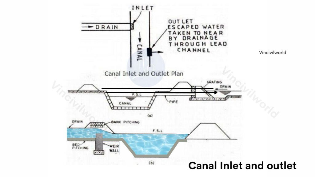
Stone pitching is provided at the bed and banks of the drainage. The maintenance cost of the inlet and outlet system is high. But the construction cost is low. The main disadvantage of this system is that they also cause soil erosion and water pollution. 

Key Takeaways

  • Cross Drainage Works: Crucial for managing the intersection of irrigation canals and drainage channels without disrupting their functions.
  • Aqueducts: Carry irrigation canals over drainage channels, preventing water mixing and ensuring stable flow, especially in uneven terrains.
  • Syphon Aqueducts: Handle higher hydraulic pressures, using enclosed conduits to maintain water flow across challenging topographies.
  • Design Considerations: Cross drainage work selection is based on factors like alignment, discharge levels, foundation capacity, and economic conditions.
  • Preventing Erosion and Flooding: These structures mitigate the risks of flooding, erosion, and waterlogging, contributing to efficient water management systems.

Conclusion

Cross drainage works, particularly aqueducts and syphon aqueducts, play a crucial role in modern water management. These structures are designed to maintain the integrity of irrigation and drainage systems, ensuring uninterrupted water flow across different terrains. Aqueducts, by carrying canals over drainage channels, prevent contamination and erosion. Syphon aqueducts, handling higher pressures, offer advanced solutions for challenging landscapes. These systems are indispensable for maintaining efficient and sustainable water management, safeguarding both agricultural productivity and infrastructure longevity.

Highway Engineering- Definition, Importance and Construction Details

Highway engineering is the branch of civil engineering that oversees the planning, design, construction and maintenance of roads and highways, a critical discipline enabling modern infrastructure. At its core, highway engineering ensures that road networks are safe, efficient, and durable. This is true whether for local streets or major expressways. When readers ask “what is highway engineering” or seek a highway engineering definition, they find that it includes geometric road layouts. It also spans pavement design, drainage, and traffic-flow planning. Understanding the importance of highway engineering becomes clear when you realize how it supports trade, mobility, and national development by facilitating swift movement of people and goods. A dedicated section on highway engineering construction shows how design transforms into physical roads that serve communities and economies.

In this article, we will also explore what highway engineering entails, its key components, and its significance in modern infrastructure. We’ll also delve into the essential aspects of road and highway engineering. We will highlight its importance in the development of safe and efficient transportation systems.

  1. Overview of Highway Engineering
    1. Importance of Highway Engineering in Modern Infrastructure
  2. What is Highway Engineering ?
  3. Importance of Highway Engineering
  4. Planning and Development of Highway Engineering
    1. What are Highway Plans?
  5. Construction of Highways: Key Aspects
    1. Technological Components
    2. Commercial Components
  6. Maintenance of highways
  7. Highway Engineering Safety
  8. Key Takeaways
  9. Conclusion

Overview of Highway Engineering

Highway engineering involves the planning, design, and construction of roads and highways, ensuring safe and efficient transportation. It covers a range of activities, from initial route selection to the final construction phase. This field combines technical expertise with practical solutions to address the needs of modern traffic systems. Road and highway engineering plays a pivotal role in enhancing connectivity, boosting economic growth, and improving overall quality of life.

Importance of Highway Engineering in Modern Infrastructure

Highway engineering is vital to the development and maintenance of modern infrastructure. It facilitates the safe and efficient movement of people and goods, supporting economic activities and social development. Engineers apply advanced techniques in road and highway engineering. They ensure that transportation networks are reliable. They also ensure that they are sustainable and capable of meeting future demands. The strategic design and construction of highways are crucial for reducing congestion, improving safety, and promoting environmental sustainability.

Highway engineering

What is Highway Engineering ?

Highway engineering is a subset of highway engineering. It deals with the planning, development, and upkeep of various types of roads, tunnels and bridges. It plays an important role in ensuring safe and efficient transport of people and goods. Highway engineering is a specialized field within civil engineering. It focuses on the planning, design, construction, and maintenance of highways and roads.

It plays a crucial role in ensuring the safety and efficiency of transportation networks. Understanding what is highway engineering involves recognizing its impact on daily travel and commerce. Highway engineering encompasses various aspects, including pavement design, traffic management, and environmental considerations. As a fundamental part of road and highway engineering, it addresses challenges related to traffic flow, safety, and sustainability. This makes it essential for the development of modern infrastructure.

It entails researching the following topics:

1) Highway planning, location, and growth.

2) The materials needed to build a highway.

3) The performance of highway traffic and its regulation.

4) Road drainage, etc.

Before we jump on to the details, let me tell you the importance of highway engineering.

Importance of Highway Engineering

Highway engineering is crucial for developing efficient transportation networks, enabling safe and rapid movement of people and goods. It enhances connectivity, reduces travel time, and supports economic growth. Understanding highway engineering is essential in designing roads that meet modern infrastructure needs. Road and highway engineering are vital for progress.

The Importance of roads is summarised below.

1. They provide transportation for people, commodities, raw materials, and other items to various parts of the world.

2. In hilly areas, they are the only means of contact.

4. Assists in the upkeep of law and order in a government.

Let’s talk a bit about the planning of highways in the next section.

Planning and Development of Highway Engineering

Planning and development in highway engineering focus on designing road networks that meet safety, efficiency, and environmental standards. By mastering the principles of highway engineering, engineers can optimize road and highway projects. This ensures these projects accommodate current and future traffic demands. It also minimizes environmental and community impacts.

Highway planning involves predicting existing and potential traffic volumes on a road network. This prediction is crucial for the success of highway engineering. It also forms a fundamental basis for highway construction. Highway engineers work diligently to anticipate and assess all potential civil consequences of highway systems.

Environmental impacts are key considerations in road and highway engineering. Factors such as noise pollution, air pollution, and water pollution must be addressed, along with other ecological impacts.

What are Highway Plans?

In highway engineering, highway plans or highway drawings are essential documents. They are created from data obtained during various surveys aimed at locating a highway. These plans include the main map, index map, preliminary survey plans, and other sketches related to the road project. Detailed plans for additional works like bridges, culverts, and railway crossings are also prepared.

Purposes and Objectives of Highway Plans:

  1. To understand how the highway will function.
  2. To estimate the cost of the road project.

Now, let’s explore the construction phase.

Construction of Highways: Key Aspects

Understanding what is highway construction is vital for ensuring that highways can handle traffic demands and minimize environmental impact. The following are the key aspects of construction of highways.

  • Planning and Design: In highway engineering, careful planning and design are crucial to ensure safety, efficiency, and durability.
  • Site Preparation: The initial step in road and highway engineering involves clearing, grading, and preparing the site.
  • Foundation Laying: Establishing a strong foundation is essential to support the road structure.
  • Surface Construction: Laying the road surface, typically with asphalt or concrete, completes the construction process.

In most cases, extensive surveys and subgrade planning precede highway construction. There are many aspects of highway design that can be broken down into technological and commercial components.

The following are some examples of each:

Technological Components

Technological components in highway engineering include advanced construction machinery, GPS-guided equipment, and smart traffic management systems. These technologies enhance efficiency, precision, and safety in road and highway projects.

  • Material quality
  • Installation techniques
  • Traffic

Commercial Components

Commercial components involve project financing, procurement of materials, and contract management. They ensure the economic viability of road and highway engineering projects by balancing costs, timelines, and resource allocation. 

  • Environmental considerations in contracts
  • Aspects of politics and law
  • Concerns from the public

Regardless of the project type, highway construction usually starts at the lowest elevation of the site and progresses upward. By looking over the project’s geotechnical requirements, we get an idea about the following:

  • Current ground condition.
  • Specific equipment requirement for excavation, grading, and material transportation to and from the site.
  • Properties of material to be excavated.
  • For below-grade work, dewatering requirement.
  • Excavation safety criteria
  • Quantities of water for dust control and compaction

How about the maintenance of highways? I will show you in the next section.

Maintenance of highways

The ultimate goal of highway maintenance is to correct flaws and maintain the structure and usability of the pavement. In order to construct an adequate maintenance plan, defects must be identified, recognised, and registered. Flexible and rigid pavements have different defects.

The four primary goals of highway maintenance are as follows:

  1. Repairing functional pavement defects helps to prolong the pavement’s functional and structural life. 
  2. Ensure road protection and signage.
  3. Keep the highway in a usable state
  4. Highway systems and all of their components can be kept in initial, as-built condition by following routine maintenance procedures.

Last, but not the least a bit about the safety.

Highway Engineering Safety

Highway engineering safety is important since it involves the life of people. Automated traffic signals can be used to further ensure this.

Highway under construction
  • Safety management is a comprehensive approach to reducing the frequency and severity of traffic incidents. 
  • The key to improving highway safety is to design, develop, and maintain highway structures. These structures need to be much more tolerant of the average range of man/machine interactions with highways.
  • Over time, technological advances in highway engineering have enhanced the methods used in design, construction, and maintenance.

Key Takeaways

  1. Highway Engineering: Essential in civil engineering, focusing on the design, construction, and maintenance of roads and highways.
  2. Modern Infrastructure: Plays a critical role in developing safe, efficient transportation systems that support economic growth.
  3. Environmental Considerations: Addressing noise, air, and water pollution is crucial in road and highway engineering.
  4. Technological Components: Advanced machinery and smart traffic systems enhance construction efficiency and safety.
  5. Commercial Components: Project financing, material procurement, and contract management ensure the economic viability of highway projects.

Conclusion

Highway engineering is a pivotal discipline in civil engineering, central to developing modern transportation networks. It encompasses planning, design, construction, and maintenance, with a strong emphasis on safety, efficiency, and environmental sustainability. Understanding the key aspects of road and highway engineering is crucial. This includes technological advancements and commercial considerations. These factors are essential for building infrastructure that meets current and future demands. By balancing these elements, highway engineering supports economic growth. It also enhances the quality of life through improved connectivity and reduced environmental impact. This field remains vital in shaping the future of global transportation systems.

MSE Retaining Walls – Components & advantages.

MSE Retaining Walls are also known as Mechanically Stabilised Earth (MSE) retaining walls. Commonly referred to as RE walls, they are a popular choice in modern construction due to their durability and cost-effectiveness. MSE retaining walls consist of layers of soil. The soil is reinforced with materials like geogrids or steel strips. This reinforcement provides essential stability against earth pressures. In this blog, we will explore the meaning of MSE walls, delve into their key components, and highlight their advantages. Additionally, we will examine real-world applications of MSE retaining walls and discuss important design considerations. By comparing RE walls with other retaining wall systems, you will gain a clear understanding of their features. This will help you decide their suitability for various construction projects.

MSE retaining walls means mechanically stabilised earth or reinforced earth. This is an earth retaining system where compacted granular soil is reinforced with horizontal layers of steel strips or geo-synthetic materials. This compacted earth is held together with thin facing elements made of Precast concrete, shotcrete or weld mesh reinforced panels. They are used extensively for constructing retaining walls, bridge abutments, highway wall systems, dykes, etc. MSE retaining walls cost almost half what a concrete structure would have cost for similar uses.

  1. What is an MSE Retaining Wall?
  2. Design basis of RE walls/MSE walls
  3. Components of a MSE retaining wall
    1. Reinforcement element
    2. Back fill materials
    3. Facing elements
    4. Drainage layer
    5. Jointing and filling materials
  4. Advantages of MSE walls
  5. Disadvantages of MSE retaining walls.
  6. Key Takeaways
  7. Conclusion

What is an MSE Retaining Wall?

An MSE retaining wall is also known as a Mechanically Stabilised Earth retaining wall. It is a structure designed to retain soil using layers of reinforced materials. MSE walls consist of compacted soil, reinforced with elements like geogrids or steel strips, providing stability against earth pressures. Often referred to as RE walls, these structures are popular due to their durability and cost-efficiency. To grasp the meaning of MSE walls, it’s essential to understand that the reinforcement materials bind the soil. This binding makes the wall robust and stable. MSE retaining walls are widely used in various construction projects, offering a reliable solution for earth retention.

Design basis of RE walls/MSE walls

When designing an MSE retaining wall, consider soil properties, such as bearing capacity and drainage, to ensure stability. Select appropriate reinforcement materials like geogrids or steel strips based on load requirements. Proper wall height and slope must be determined to manage earth pressures. Additionally, incorporate effective drainage systems to prevent water buildup behind the RE wall.

Components of a MSE retaining wall

An MSE retaining wall consists of several critical components that work together to provide stability and strength. These RE wall components include reinforced soil layers, facing panels, and drainage systems. The mechanically stabilised earth retaining wall relies on the interaction between the soil and reinforcement materials. Examples of these materials include geogrids or steel strips. This interaction helps to withstand earth pressures. Understanding these key elements is essential for designing a durable and effective MSE wall. The key components of a RE wall system is as follows.

a) Reinforcing element

b) Back fill materials

c) Fascia element

MSE walls or RE walls
MSE Walls or RE walls (Typical Section)
Typical section of MSE Retaining wall

Reinforcement element

The reinforcing elements of an MSE retaining wall are vital for its stability and strength. These elements typically include geogrids, steel strips, or geotextiles, which are embedded within the soil layers. The reinforcing materials work by binding the soil, creating a unified mass that resists earth pressures. In a mechanically stabilised earth retaining wall, these elements effectively distribute loads and prevent the wall from shifting or collapsing. The careful selection and installation of reinforcing elements are crucial for ensuring the long-term durability and performance of the RE wall.

The reinforcements are used to reinforce and provides the requisite tensile strength to hold the soil together. Two types of reinforcing elements are used in MSE walls. They are metallic and polymeric reinforcements. Metallic reinforcements (In-extensible) include Galvanised iron ribbed strips (50mm-100mm) or ladder strip arrangements.

Polymeric reinforcement (Extensible reinforcement) could be geo-grids or geo-textiles, which are preferred in corrosive environments. For any vertical and horizontal obstructions, reinforcements are bend at an angle, not more than 15 degrees.

Geo grids for reinforcing RE walls
Geo grids for RE walls

Appropriate connections hooks are embedded behind the fascia walls for the anchorage of geo-grids and metal reinforcements.

Back fill materials

For an MSE retaining wall, it is essential that the selected backfill materials are cohesionless. They must meet strict criteria, including gradation, plasticity, organic content, and electrochemical properties. These materials must be free-draining with minimal fine content. The soil friction angle for the MSE retaining wall must be verified by shear tests. The angle of interface friction between the compacted fill and the reinforcing element should be no less than 30 degrees, as specified by IS 13326 Part 1.

Fly ash Backfill

FLY ASH BACK FILL

Fly ash can be used as backfill for the RE wall, provided it adheres to applicable standards. The selected backfill should be placed parallel to the MSE retaining wall. It should start approximately three feet from the back of the wall panels. The backfill should be compacted in 6-inch lifts. Additionally, soil materials may be placed without reinforcement between the stabilised zone and the natural ground surface. This is known as retained backfill. It ensures the stability and effectiveness of the mechanically stabilised earth retaining wall.

Facing elements

Facing elements in an MSE retaining wall serve to retain filled materials. They prevent local slumping on steeply sloping faces. They also align with both structural and aesthetic requirements. These facings are commonly made of materials such as precast reinforced cement concrete, plain concrete hollow blocks, or similar components.

Facing elements
Facing Element of RE walls

Drainage layer


For the RE wall, it is essential to incorporate a suitable drainage system in the embankment area. This prevents water logging. A drainage layer, approximately 2-3 feet wide, is installed on the backside of the mechanically stabilised earth retaining wall. This layer uses free-draining material to facilitate proper water drainage from the reinforcement zones. This ensures the stability and effectiveness of the MSE retaining wall.

Drainage layer (image courtesy : Science direct)

Jointing and filling materials

Rubber or wooden bearing pads are used between horizontal joints of facing elements. This ensures there shall not be any concrete to concrete joints. The interior panel joints are sealed with geotextile filler cloth in the horizontal and vertical directions as shown in fig. This is done to ensure that no interior back fill materials sweep through the joints.

RUBBER PADS AND GEO TEXTILE LAYER

Advantages of MSE walls

MSE walls, or Mechanically Stabilised Earth walls, are favored for their economic and construction benefits. They enable rapid and efficient construction with minimal disruption to traffic and other services. MSE retaining walls offer a variety of materials and customization options, enhancing their popularity as earth-retaining systems. The fascia elements, backfill, and reinforcing system work together to form a gravity retaining structure. This structure relies on the self-weight of the reinforced soil mass. It resists lateral pressures from earth, service loads, seismic forces, and hydrostatic pressure. The flexibility and efficiency of RE walls make them a top choice in modern construction.

  • Heavy Load Capacity: Can support extremely heavy loads such as bridge abutment footings, crane loads, and service loads.
  • Seismic and Dynamic Resistance: Designed to resist seismic and dynamic forces, distributing bearing pressure over a wide area.
  • Faster Construction: Enables quicker construction compared to conventional retaining walls.
  • Minimal Site Preparation: Requires less site preparation and can be built in confined areas where other retaining walls are impractical.
  • No Additional Supports: No need for additional supports, finishes, or curing time.
  • Free Drainage: Granular backfill facilitates free drainage through panel joints, reducing hydrostatic pressure.
  • Lightweight and Precast Fascia: Fascia walls are lightweight, precast, and easily transported and lifted using simple equipment.
  • Customizable: Can be made to any height, customized for designs and logos, and adjusted to manage obstructions.
  • Versatile Construction: Can be tailored to any geometry, requiring no heavy machinery or specialized workers.
  • Durable Service Life: Provides a long service life even under extreme loading and complex conditions.

Disadvantages of MSE retaining walls.

  • MSE retaining walls require granular material in huge quantities. Areas where there is a scarcity of granular material the construction cost increase and make the structure uneconomical.
  • The corrosion or reinforcement and deterioration of geo-grids on exposed to sunlight has to be addressed. The reinforced component must be designed to withstand erosion and corrosion processes. These processes can highly deteriorate the mechanical behavior of the composite structure.
  • Proper drainage system should be provided.
  • The wall must obtain a minimum width in order to acquire adequate stability

Key Takeaways

  1. MSE Walls: Mechanically Stabilised Earth (MSE) retaining walls, also known as RE walls, offer durability and cost-efficiency.
  2. Components: Include reinforcing elements (geogrids, steel strips), backfill materials, facing elements, drainage layers, and jointing materials.
  3. Load Capacity: Capable of supporting heavy loads like bridge abutment footings and crane loads.
  4. Seismic Resistance: Designed to handle seismic and dynamic forces effectively.
  5. Construction Speed: Allows for rapid and efficient construction with minimal disruption.
  6. Customization: Flexible design options for various geometries and aesthetics.
  7. Free Drainage: Ensures effective water management to prevent hydrostatic pressure buildup.
  8. Durability: Long service life even under extreme conditions.

Conclusion

MSE retaining walls, or Mechanically Stabilised Earth walls, present a robust and economical solution for earth retention in modern construction. Their design incorporates various components, including reinforcing elements, backfill materials, and drainage systems, to ensure stability and functionality. MSE walls excel in supporting heavy loads, resisting seismic forces, and allowing rapid construction with minimal disruption. Customizable and versatile, they offer long-term durability and can be adapted to diverse project requirements. However, challenges such as the need for granular material and addressing potential reinforcement corrosion must be managed. Overall, MSE walls are a valuable option for efficient and effective retaining wall systems.

Construction Joints in Concrete | Types and applications

Construction joints in concrete are a crucial and fundamental part of civil engineering and construction. Changes in temperature and moisture can cause concrete to expand and contract. Because concrete is weak in tension, shrinkage and volume change in concrete cause cracks. The construction joints installed at strategic locations prevent the formation of cracks in concrete and the development of tensile stresses.

Understanding the types and purposes of these joints is vital for effective concrete construction. Transitioning from design to installation, proper management of construction joints ensures a long-lasting and resilient concrete structure.This article discusses the significance of construction joint types in concrete structures like slabs and pavements etc and their applications and features

  1. What is a construction joint in concrete ?
  2. Construction joints in concrete – Significance
  3. Types of Joints in Concrete
    1. Construction Joints in Concrete: Purpose and Types
    2. Types of Construction Joints in concrete
    3. Expansion joints in concrete
    4. Types of Expansion Joints
  4. Contraction Joints in Concrete: Purpose and Types
    1. Types of Contraction Joints
  5. Summary of Differences – Joints in concrete
    1. Intentionality
  6. Movement Accommodation
    1. Reinforcement Continuity
  7. Design Considerations for Construction Joints
    1. Factors Influencing Joint Placement
    2. Design Guidelines and Best Practices
  8. Material choice for Joints
  9. Construction and Installation Techniques
    1. Preparing the Site and Surface
    2. Installing Construction Joints: Step-by-Step
  10. Common Challenges and Solutions
  11. Key Takeaways
  12. Conclusion

What is a construction joint in concrete ?

A construction joint is a type of concrete joint used when a new section of concrete is poured next to an already set section of concrete. The purpose of a construction joint is to allow for some horizontal movement. It remains rigid against rotational and vertical movement. Concrete slab construction joints help control cracking and accommodate shrinkage or thermal expansion.

Construction joints in concrete – Significance

Construction joints in concrete are vital for the stability and longevity of concrete structures. These joints, like concrete construction joints and slab construction joints, help manage the stresses and movements. Concrete undergoes changes during curing and environmental changes. Properly placed concrete slab construction joints prevent uncontrolled cracking and make sure that construction joints in concrete slabs work effectively. They allow for natural expansion and contraction while maintaining structural integrity. Builders can address potential issues by understanding and implementing the right type of construction joints. This leads to more durable and reliable concrete structures. Hence, effective management of these joints is crucial for successful concrete construction.

Types of Joints in Concrete

Construction joints in concrete are crucial for managing movement and stress in concrete structures. Different types serve various functions, each ensuring the durability and performance of the structure. On the basis of functions construction joints in concrete are classified as follows.

  • Construction Joints
  • Expansion Joints/Control Joints
  • Isolation Joints

Related posts from vincivilworld

Construction Joints in Concrete: Purpose and Types

Construction is often a time-consuming process. Construction joints in concrete play a crucial role in managing this. They separate large concrete work into smaller, more manageable units. These joints are particularly useful in locations where construction stops at the end of the day’s work. A construction joint is a specific type of concrete joint. It is used when a new section of concrete is poured next to an already set section. These joints ensure effective bonding between different pours while accommodating structural movement. They are vital for preventing cracks and maintaining the overall integrity of the structure.

Types of Construction Joints in concrete

  1. Butt Joints: Connect two concrete slabs without overlapping.
  2. Tongue and Groove type or Keyed Joints: Feature interlocking sections for added strength.
  3. But type Construction joints with dowel bars or Dowel Joints: Use dowels to align and transfer loads between slabs.
  4. Groove Joints: Formed by creating grooves in fresh concrete for controlled cracking.

Properly placed construction joints in concrete slabs ensure that the structure remains stable and durable over time.

Concrete construction joints in concrete
Illustration of different types of construction joints in concrete, including butt joints and tongue and groove joints.

On the basis of the structure, the construction joint can be vertical, horizontal and inclined. It is suitable for the construction of large slabs, irrigation channels, etc. These joints consist of keys at definite intervals. These keys help in resuming the work the next day. It also helps in uniform load distribution.

Expansion joints in concrete

Concrete construction often faces challenges due to the expansion of concrete from temperature and moisture changes. This expansion can lead to cracks and even structural failure. To address this, construction joints in concrete, particularly expansion joints, are used. These joints, also known as control joints, allow for controlled expansion of the concrete without causing stress, thus preventing cracks. For buildings longer than 45 meters, it’s common to include one or more expansion joints. In India, the recommended spacing is 30 meters. The joints are created by leaving a space between concrete slab construction joints. This space is typically at a depth of one-fourth the slab thickness. These concrete construction joints can be installed either before or after the concrete is laid. Effective performance is ensured by cutting the joints deeply.

Types of Expansion Joints

  1. Compression Seal Joints: Use flexible materials that compress and expand with temperature changes.
  2. Sliding Plate Joints: Feature metal plates that slide over each other, allowing movement.
  3. Strip Seal Joints: Use rubber strips to absorb movement and seal against moisture.
  4. Bellows Joints: Use a flexible, accordion-like structure to accommodate movement in multiple directions.

These types of expansion joints are essential for maintaining structural integrity. They include construction joints in concrete slabs. They prevent cracks and ensure long-term durability in concrete structures. Proper placement and installation of these joints are crucial for the success of any concrete construction project.

Expansion joints are essential in bridges, pavements, and railway tracks. They are also vital in other large concrete structures. They ensure durability and prevent stress-related damage over time.

A concrete expansion joint depicted on a roadway, featuring a zigzag pattern to accommodate movement, ensuring structural integrity and preventing cracks.
Expansion joint in concrete pavement, designed to accommodate temperature-induced movement.

Contraction Joints in Concrete: Purpose and Types

Concrete is weak in tension, so when it contracts during hardening, it induces stress that can lead to cracks. To prevent unnecessary cracking, contraction joints in concrete are essential. These construction joints are installed before the concrete is laid. They are particularly useful in projects such as roads, retaining walls, floors, tunnels, and canals. Typically, contraction joints are spaced between 5m to 10m apart. Jointing tools are used for their installation. In reinforced concrete, contraction joints can often be avoided. In un-reinforced or lightly reinforced slabs, these joints are crucial. They minimize crack formation and maintain the structural integrity of the concrete.

Types of Contraction Joints

  1. Sawed Joints: Created by sawing a groove into the hardened concrete slab.
  2. Tooled Joints: Formed by hand-tooling a groove into the concrete while it’s still wet.
  3. Pre-molded Joints: Use pre-molded inserts placed into the concrete slab construction joints to create a controlled crack.
  4. Formed Joints: Created by placing a strip of material in the concrete before it hardens to guide controlled cracking.

These types of contraction joints are vital in concrete slab construction joints, ensuring that the structure remains durable and free from random, damaging cracks. Proper placement of these joints helps maintain the structural integrity and appearance of the concrete.

Diagram illustrating a contraction joint in concrete, labeled with a plastic or hardboard preformed strip.
Illustration of a contraction joint in concrete, highlighting the use of a plastic or hardboard preformed strip for effective stress management.

Summary of Differences – Joints in concrete

Intentionality

Intentional Joints: Contraction, Isolation, Expansion, and Construction joints are deliberately incorporated into design. They help manage structural behavior. These joints also facilitate building processes.

Unintentional Joint: Cold joints arise from unplanned delays and require remediation to ensure structural soundness.

Movement Accommodation

  • Contraction Joints: Control crack locations due to shrinkage.
  • Isolation Joints: Allow independent movement in all directions between connected structures.
  • Expansion Joints: Accommodate expansion and contraction primarily due to temperature changes.
  • Construction Joints: Facilitate construction without necessarily accommodating movement unless designed to do so.
  • Cold Joints: Do not accommodate movement and may pose structural issues if not addressed.

Reinforcement Continuity

Interrupted Reinforcement: Isolation and sometimes expansion joints interrupt reinforcement to allow for movement.

Continuous Reinforcement: Contraction and construction joints typically allow reinforcement to pass through, maintaining structural continuity.

Affected Reinforcement: Cold joints may inadvertently disrupt reinforcement continuity due to placement delays.

Design Considerations for Construction Joints

Factors Influencing Joint Placement

Factors influencing the placement of construction joints in concrete include load requirements, environmental conditions, and the size of the structure. Proper placement ensures effective stress management and minimizes the risk of cracking. Consideration of these factors helps in deciding the type and location of concrete construction joints.

Design Guidelines and Best Practices

Designing construction joints in concrete involves ensuring proper alignment and spacing to manage stresses effectively. Best practices include adhering to recommended joint spacing and depth, using proper sealing materials, and coordinating joint placement with construction phases. This approach helps maintain the structural integrity of concrete slab construction joints.

Material choice for Joints

Selecting appropriate materials for construction joints in concrete is crucial for ensuring durability and performance. Common materials include joint sealants, fillers, and reinforcement products. The choice depends on the joint’s role and environmental exposure. This ensures that concrete slab construction joints perform effectively under various conditions.

Construction and Installation Techniques

Effective construction and installation of construction joints in concrete involve several steps. Proper site and surface preparation is essential. You should follow detailed installation procedures. By doing so, you can address common challenges. These steps help ensure that concrete construction joints are functional and durable. Adhering to these techniques minimizes the risk of issues in concrete slabs.

Preparing the Site and Surface

Preparing the site and surface for construction joints involves cleaning and leveling the area where joints will be placed. This step ensures proper adhesion and alignment of concrete slab construction joints. It is essential for achieving a smooth finish. This also prevents future issues in the concrete structure.

Installing Construction Joints: Step-by-Step

Installing construction joints in concrete involves several steps: marking the joint locations, placing formwork, pouring concrete, and finishing the surface. Accurate placement of concrete construction joints is crucial. Proper finishing techniques ensure they function as intended. These aspects enhance structural durability.

Common Challenges and Solutions

Common challenges with construction joints in concrete include misalignment, insufficient sealing, and inadequate curing. Solutions involve meticulous planning, using quality materials, and following best practices for installation. Addressing these issues helps maintain the integrity of construction joints in concrete slabs and ensures long-term performance.

Key Takeaways

Construction joints in concrete are essential for managing stress and movement within concrete structures. Properly placed concrete construction joints, such as slab construction joints and concrete slab construction joints, help prevent cracks and maintain structural integrity. Understanding the types of construction joints in concrete slabs—expansion joints, contraction joints, and others—ensures effective control of movement and stress. Key factors influencing joint placement include load requirements, environmental conditions, and structure size. By implementing best practices in design, material selection, and installation, builders can enhance the durability and performance of concrete structures, leading to long-lasting and reliable results.

Conclusion

Incorporating construction joints in concrete is crucial for the stability and longevity of concrete structures. These joints manage the stresses and movements that concrete undergoes during curing. This includes concrete construction joints and slab construction joints. Environmental changes also affect the movements. Proper placement of various types of joints is crucial to control cracking. Understanding expansion and contraction joints is essential to maintain structural integrity. Builders should adhere to design guidelines and select appropriate materials. They must also follow correct installation techniques. These actions ensure that construction joints in concrete slabs function effectively. This comprehensive approach not only addresses potential issues but also contributes to the overall durability and reliability of concrete structures.

GATE Exam 2024 CE | Date, Application Process, online coaching

The Graduate Aptitude Test in Engineering (GATE) is one of the most prestigious national-level entrance exams in India. Each year, the Indian Institute of Science (IISc) and seven Indian Institutes of Technology (IITs) take turns conducting the exam. The GATE exam tests the aptitude of engineering and science graduates aspiring for higher education and jobs in the field of engineering, technology, and research. In this article, we will discuss the GATE CE Exam Notification 2024, including the exam date, application process, syllabus, eligibility criteria, gate exam score and result.

  1. Introduction to GATE exam.
  2. GATE CE Exam Notification 2024
  3. Eligibility Criteria
  4. Exam Date and Schedule
  5. Application Process
  6. Exam Pattern and Syllabus
  7. Admit Card and Exam Centers
  8. Result and Scorecard
  9. Cut-Off Marks and Qualifying Criteria
  10. Counselling and Admission Process
  11. GATE CE Exam Online Coaching
  12. Conclusion

Introduction to GATE exam.

The GATE exam administers 27 computer-based tests, including one for Civil Engineering (CE). The GATE CE exam tests candidates’ understanding of civil engineering topics. It includes Structural Engineering, Geotechnical Engineering, and Water Resources Engineering. The exam also covers Environmental Engineering, Transportation Engineering, and Construction Management.

GATE EXAM 2024

GATE CE Exam Notification 2024

The Indian Institute of Science (IISc) released the GATE CE Exam Notification 2024 on August 10, 2023. For further details, visit the official website for GATE 2024 at gate.iisc.ac.in. The notification includes all essential information about the exam. Specifically, it covers the exam date, schedule, eligibility criteria, syllabus, application process, exam pattern, admit card, exam centers, result, scorecard, and cut-off. Additionally, the notification provides guidance on how to navigate each aspect of the exam, ensuring that candidates are well-prepared and informed.

Eligibility Criteria

The eligibility criteria for the GATE CE exam are as follows:

  • The candidate must have a Bachelor’s degree in Engineering/Technology/Architecture or Master’s degree in any relevant Science subject.
  • The candidates appearing in the final year of their qualifying exam are also eligible to apply.
  • There is no age limit to appear for the GATE exam.
GATE EXAM -2024

Exam Date and Schedule

The GATE CE exam is scheduled to be held on February 3, 4, 10, and 11, 2024. The exam will be conducted in two sessions, i.e. The forenoon session from 9:00 am to 12:00 pm and the afternoon session from 2:00 pm to 5:00 pm.

Application Process

The application process for the GATE CE exam is entirely online. Candidates can apply for the exam by visiting the official website at gate.iisc.ac.in. Furthermore, the application fee is Rs. 1500 for General and OBC candidates, whereas it is Rs. 750 for SC, ST, and PwD candidates. Therefore, candidates should ensure they meet the eligibility requirements and submit their applications before the deadline to avoid any inconvenience. The last date to apply for the exam is September 15, 2023.

Exam Pattern and Syllabus

The GATE CE exam consists of 65 questions for a total of 100 marks. The exam is divided into two sections, i.e., General Aptitude (15 marks) and Technical (85 marks). The Technical section consists of two types of questions, i.e., Multiple Choice Questions (MCQs) and Numerical Answer Type (NAT) questions.

The syllabus is divided into seven broad sections.

  • Engineering Mathematics
  • Structural Engineering
  • Geotechnical Engineering
  • Water Resources Engineering
  • Environmental Engineering
  • Transportation Engineering
  • Construction Management.

Each section has several topics, and the detailed syllabus is available on the official website.

Admit Card and Exam Centers

The GATE CE exam admit card will be available for download on the official website. Candidates should download and print the admit card and bring it to the examination center. Additionally, they must carry a valid photo ID as proof of identity.

The exam centers for the GATE CE exam will be spread across multiple cities in India and a few international cities. Candidates can choose up to three exam centers in order of preference during the application process. The exam conducting authority will allocate the exam center based on availability and feasibility.

Result and Scorecard

The official website declared the result of the GATE CE exam 2024 on March 30, 2024. Candidates can download their scorecards from April 1, 2024, onwards. The scorecard will include the candidate’s name, registration number, marks obtained, and the All India Rank (AIR). Additionally, the GATE score is valid for three years from the result declaration date.

Cut-Off Marks and Qualifying Criteria

The GATE CE exam cut-off marks are the minimum marks that candidates need to obtain in order to qualify for the exam. The cut-off marks vary every year based on factors such as the difficulty level of the exam and the number of candidates appearing for the exam. The qualifying criteria for the GATE CE exam is that the candidate should obtain a minimum of 25 marks out of 100.

Counselling and Admission Process

The GATE CE exam score is accepted by several institutes and universities in India for admission to postgraduate courses in Civil Engineering and related fields. Additionally, the counseling and admission processes vary among different institutes and universities. Consequently, candidates need to apply separately to the institutions of their choice. Furthermore, they must navigate each institution’s specific counseling and admission procedures. Thus, it is essential for candidates to stay informed about the requirements of each institute or university to ensure a smooth admission process.

GATE CE Exam Online Coaching

If you’re aspiring to crack the GATE CE exam, then opting for GATE CE online coaching can be a game-changer for you. With the convenience of learning from anywhere and anytime, online coaching offers a plethora of benefits to students. Not only do you get access to expert faculty members, but also high-quality study material and mock tests that are crucial for exam preparation. Additionally, online coaching also saves you the time and effort of commuting to a physical classroom, allowing you to utilize that time for self-study and revision. So, enrol in a reliable GATE CE exam online coaching program today, and give yourself the best chance of acing the exam.

Conclusion

The GATE CE exam is an important examination for aspiring Civil Engineers. It provides a platform for candidates to showcase their knowledge and skills in the field of Civil Engineering and helps them to get admission to some of the most reputed institutes and universities in India. Candidates should prepare well for the exam by following the exam pattern and syllabus, practising the previous year’s question papers, and taking mock tests. They should also keep themselves updated with the latest exam notifications and announcements.ouncements.

Pervious Concrete | Innovative Water Management Solution

Pervious concrete is a modern eco-friendly solution for outdoor surfaces, tackling drainage issues like standing water and surface flooding. While it’s more expensive than traditional concrete, it provides effective water management and environmental benefits. Discover more about pervious concrete mix design, functionality, benefits, drawbacks, and cost considerations.

  1. What Is Pervious Concrete?
  2. Pervious concrete – How Does It Work?
  3. Benefits of Pervious Concrete
    1. Minimal Runoff
    2. Reduced Pollution
    3. Lower Need for Drainage Systems
    4. Cooler Surface
    5. Reduced Freezing Risk
    6. Environmental impact and sustainability
  4. Best practices for annual maintenance of pervious concrete
  5. Drawbacks of Pervious Concrete
    1. Lower Strength
    2. Maintenance Needs
    3. Challenges for DIY Projects
    4. Soil Compatibility
  6. Pervious Concrete pavements
  7. Cost Considerations of Pervious Concrete
  8. Conclusion

What Is Pervious Concrete?

Pervious concrete, used for “flat work” such as patios, driveways, sidewalks, walkways, and sometimes parking lots, is defined by ACI 522R as a zero-slump, open-graded material.

Pervious concrete mix design includes portland cement, coarse aggregate, minimal fine aggregates, admixtures, and water.

These components create a hardened material with interconnected pores (0.08 to 0.32 inches or 2 to 8 mm), allowing for easy water infiltration.

Pervious Concrete
Pervious Concrete

The void content ranges from 18% to 35%, with compressive strengths of 400 to 4000 psi (2.8 to 28 MPa).

The drainage rate varies with aggregate size and mixture density, generally falling between 2 to 18 gallons per minute per square foot (81 to 730 liters per minute per square meter).

Pervious concrete – How Does It Work?

Unlike regular concrete, pervious concrete contains minimal to no sand in its composition. The absence of sand creates a larger volume of voids (15% to 25% of the total aggregate volume), making it more porous. This increased porosity enables water to drain through the material instead of collecting on the surface.

Pervious concrete can effectively drain water, storing up to 1 inch of rainwater within its voids with a 5-inch thick surface, and up to 3 inches when poured over a 6-inch sub-base of gravel or crushed rock.

Preamble concrete drains water at a rate of 3 to 8 gallons per square foot per minute, providing efficient drainage even during heavy rainfall.

Benefits of Pervious Concrete

  • Pervious concrete offers significant advantages due to its ability to manage water effectively and reduce runoff.
  • It promotes groundwater recharge, minimizes surface flooding, and supports environmentally sustainable construction practices, making it a valuable choice for various outdoor applications.

Let us dive into the details..

Minimal Runoff

Pervious concrete directs water into the soil rather than stormwater drains, making it ideal for areas prone to overwhelmed drainage systems during heavy rainfall. This can be particularly helpful in urban areas where outdated or undersized drainage systems can get overwhelmed by rainfall.

Pervious Concrete

Reduced Pollution

Pervious concrete typically requires fewer sealers or bonders than traditional concrete, resulting in cleaner stormwater runoff and reduced environmental contaminants. According to the National Library of Medicine, this leads to fewer contaminants in stormwater runoff, providing a significant environmental benefit.

Lower Need for Drainage Systems

Its natural drainage capabilities often eliminate the need for additional drainage systems, potentially lowering installation costs. In some cases, drainage systems are required in or around driveways, patios, and parking lots. Since pervious concrete drains water naturally, it often doesn’t need any additional system installed, which means lower installation costs in some cases.

Cooler Surface

The voids in pervious concrete reduce heat retention, providing a cooler walking surface during warmer weather. This can be beneficial for outdoor spaces like patios and walkways, enhancing comfort during hot summer months.

Reduced Freezing Risk

Due to minimal water accumulation on its surface, pervious concrete reduces the risk of freezing and becoming a slippery hazard. Consequently, it provides a safer option for areas susceptible to freezing temperatures and ice formation.

Environmental impact and sustainability

  • Pervious concrete contributes positively to the environment by promoting groundwater recharge and reducing stormwater runoff, which helps mitigate urban flooding and water pollution.
  • Its sustainable attributes extend to lower heat island effects due to reduced heat retention, and less reliance on drainage infrastructure, thus conserving resources.
  • With proper maintenance, pervious concrete can offer long-term durability, supporting eco-friendly construction practices that enhance urban resilience and environmental sustainability.

Best practices for annual maintenance of pervious concrete

  • Annual maintenance of pervious concrete is crucial for preserving its drainage efficiency and longevity.
  • Best practices include regular vacuuming to remove debris, especially from the surface and within pores, to prevent clogging.
  • Pressure washing with low-pressure water helps clear out finer particles without damaging the concrete.
  • Inspecting and repairing any cracks promptly ensures structural integrity and prevents water from pooling on the surface.
  • Applying a new layer of sealer as needed helps maintain permeability.
  • Overall, proactive maintenance ensures that pervious concrete continues to function effectively in managing stormwater and supporting sustainable urban infrastructure.

Drawbacks of Pervious Concrete

While beneficial, pervious concrete has limitations that may restrict its use in certain projects:

Lower Strength

Without fine aggregates, pervious concrete is weaker than traditional concrete, limiting its use to non-structural applications. It’s not suitable for heavily trafficked surfaces like roadways or structural purposes like foundations.

Maintenance Needs

Voids in pervious concrete can clog with debris over time. This needs annual maintenance to preserve its drainage efficiency. Regular cleaning and upkeep are necessary to prevent blockages and maintain optimal performance.

Challenges for DIY Projects

Larger applications of permeable concrete can be challenging for DIYers due to precise mixing requirements and installation techniques. However, proper knowledge and expertise are essential to ensure successful installation and functionality.

Soil Compatibility

Pervious concrete may not be suitable over expansive soils like clay, which can affect its structural integrity and performance. Soil expansion and contraction can lead to cracking and compromise the concrete’s strength.

Pervious Concrete pavements

They are best suited for flat work applications such as pavements for

  • Driveways
  • Walkways
  • Patios
  • Parking Lots

Additionally, it is used in various other applications, including:

  • Streets and Road Shoulders: Enhances drainage and reduces surface water accumulation.
  • Bridge Embankments: Minimizes erosion risks by managing water flow and stabilizing soil.
  • Edge Drains: Provides effective water capture and drainage solutions along pavements.
  • Tennis Courts and Swimming Pool Decks: Ensures safe and functional surfaces with efficient water drainage.
  • Golf Cart Paths: Supports golf cart traffic while maintaining natural water drainage patterns.
  • Greenhouse Floors: Facilitates efficient water management and soil health in agricultural settings.
  • Zoo Areas and Animal Barns: Improves animal habitat conditions by aiding natural water filtration and drainage.

Cost Considerations of Pervious Concrete

Pervious concrete typically costs between $8 and $20 per square foot, including materials and labor—approximately double the cost of traditional concrete.

  • Driveway: $1,440 to $5,280
  • Walkway: $640 to $5,600
  • Patio: $1,340 to $7,200

While initial costs are higher, long-term savings may be realized through reduced need for drainage systems and lower maintenance expenses. Additionally, using pervious concrete can potentially lower overall project costs by eliminating the need for extensive drainage infrastructure.

You’ll likely find that the total cost of hiring a local concrete contractor for a larger project like a driveway or parking lot will often be less expensive when using pervious concrete. Using permeable concrete will demand a thicker slab to be poured for strength, but the lack of a drainage system beneath the concrete can end up saving money overall.

Conclusion

Pervious concrete provides a sustainable solution for water runoff management and improving outdoor living areas. Knowing its advantages, disadvantages, and costs will help you determine if it’s the right choice for your project and environmental concerns.

As cities grow and environmental challenges increase, permeable concrete will play a growing role in sustainable construction practices, helping to build resilient communities worldwide. Its ability to facilitate groundwater recharge, reduce surface runoff, and support green infrastructure makes it an essential component in modern urban planning and development, particularly in the construction of pervious concrete pavements (PCP). Check out the blog for details on design considerations, performance factors, and limitations of PCP.

Updates in civil engineering, architecture finishes, building construction, Environmental Engineering