Thermal Bridging in Buildings occurs when heat transfers through parts of a structure. This happens where insulation is reduced or interrupted. In construction practice, thermal bridges often happen at junctions, edges, and penetrations. High thermal conductivity materials allow heat to escape in these areas. Understanding the types of thermal bridging helps designers identify repeating, geometric, and point bridges within building envelopes. The causes of thermal bridging often include poor design detailing, structural elements passing through insulation, and improper installation practices. Over time, the effects of thermal bridging lead to heat loss, higher energy consumption, surface condensation, and mould growth. Additionally, thermal bridging insulation issues reduce overall thermal performance and occupant comfort. Addressing these aspects early improves energy efficiency, durability, and sustainability in modern building design.
Thermal bridging can have a major impact on a dwelling’s overall thermal efficiency, even in very well-insulated homes. According to recent studies, thermal bridging has been found to be responsible for up to 30% of a home’s heat loss.
In this blog, I will show you what exactly is thermal bridging, its consequences, causes, types and strategies to reduce them. Let’s get started.
- What is a thermal bridges in Buildings and Construction ?
- Effects of Thermal Bridging
- Thermal Bridging Causes
- Types of Thermal Bridging
- Why should we avoid thermal bridging?
- Strategies to reduce Thermal Bridging
- Key Takeaways
- Conclusion
What is a thermal bridges in Buildings and Construction ?
A thermal bridge is a part of an object that has a higher thermal conductivity than the surrounding areas. This allows heat to flow through it with the least amount of resistance. The object’s thermal resistance is reduced as a result of thermal bridges. It is also known as a cold bridge, heat bridge, or thermal bypass.
Thermal Bridging occurs when heat flows away easily through a part of the construction. This part has much less thermal resistance compared to its surroundings. This leads to uneven heating in a building.
Thermal bridges in buildings and construction are areas within a structure where heat flows more easily. This happens due to breaks or weaknesses in insulation. These bridges usually occur at junctions between walls, floors, roofs, balconies, and around openings such as windows and doors. When materials with high thermal conductivity pass through insulated layers, they create paths for heat loss during winter. They also lead to heat gain in summer. As a result, thermal bridges reduce energy efficiency. They increase heating and cooling demand. They may also cause surface condensation and mould growth. Identifying and minimizing thermal bridges in buildings and construction is essential for improving thermal performance, occupant comfort, and long-term building durability.
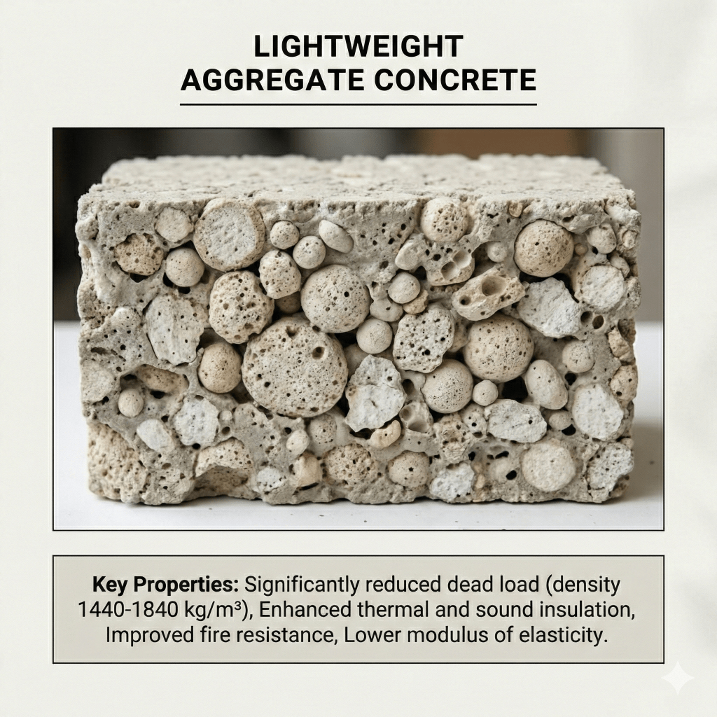
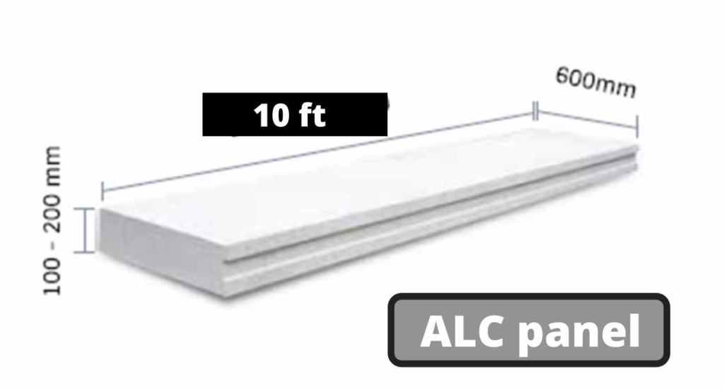
Also read : ALC Panels – Aerated Light Weight Concrete panels- Overview
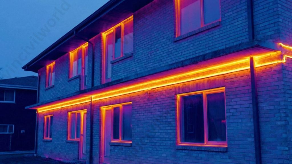
Effects of Thermal Bridging
Effects of thermal bridging significantly influence the energy performance and durability of buildings. Thermal bridging occurs when heat transfers through areas with reduced insulation, creating unwanted heat loss or heat gain. In buildings and construction, these weak points lower thermal efficiency and negatively affect indoor comfort. Understanding the effects of thermal bridging helps engineers and designers improve insulation detailing, reduce energy consumption, and enhance building performance.
- Thermal bridging in buildings will increase the amount of energy needed to heat and cool a room.
- Results in condensation of moisture inside the building envelope
- Cause thermal discomfort.
- Causes additional heat losses in colder climates and require more energy to mitigation
- Increased heat loss in winter and heat gain in summer
- Higher energy consumption and utility costs
- Reduced overall thermal performance of the building envelope
- Formation of cold spots on internal surfaces
- Risk of surface condensation
- Growth of mould and mildew
- Discomfort for occupants due to temperature variations
- Degradation of building materials over time
- Reduced lifespan of insulation systems
- Failure to meet energy efficiency standards and regulations
Thermal Bridging Causes
Thermal bridging causes arise mainly from design and construction gaps where insulation is interrupted. This interruption allows heat to pass through structural elements and junctions. As a result, energy efficiency in buildings is reduced.
- The points where the wall and the floor come together
- Wall-to-roof junctions
- Pipe and cable access holes in the building envelope
- Window and door reveals
- Steel wall links in masonry work, (e.g. cavity walls)
Types of Thermal Bridging
Types of thermal bridging describe the different ways heat flows through building elements where insulation is reduced or interrupted. Identifying these types helps designers control heat loss, improve energy efficiency, and prevent moisture-related problems in buildings and construction.
There are several types of thermal bridges, which can be further classified as follows:
- Geometric thermal bridging
- Material thermal bridging
- Structural thermal bridging
- Repeating thermal bridging
- Point thermal bridging
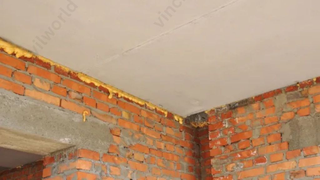
Geometrical Thermal Bridges
Geometrical thermal bridges are induced by the building’s geometry, as the name implies. They are more likely to occur with complex building forms. So it’s best to keep the overall design as simple as possible to avoid them. The examples include:
- Corners of exterior walls
- Wall-to-floor junctions
- Wall-to-roof junctions
- Junctions between adjacent walls
Material Thermal Bridging
Material thermal bridging occurs when building materials with high thermal conductivity pass through or replace insulation layers. Materials such as steel, concrete, and aluminum allow heat to transfer more easily than insulating materials. As a result, heat escapes in winter and enters the building during summer, reducing energy efficiency. Material thermal bridging commonly occurs in wall studs, beams, columns, and fasteners. Identifying and minimizing material thermal bridging is essential to improve insulation performance, reduce energy loss, and enhance indoor comfort in buildings and construction.
Structural Thermal Bridging
Structural thermal bridging occurs when structural elements penetrate the building envelope and interrupt continuous insulation. Elements such as balconies, floor slabs, columns, and cantilevered beams create direct heat flow paths. These structural connections significantly increase heat loss and may cause surface condensation and thermal discomfort. Structural thermal bridging is common in reinforced concrete and steel structures. Proper detailing, thermal breaks, and improved design strategies help reduce structural thermal bridging and improve overall thermal performance in buildings.
Repeating Thermal Bridges
Repeating thermal bridges follow a trend. And it is “repeated” over a large area of the building’s thermal envelope. The examples include:
- Steel wall ties used in masonry cavity wall construction
- Ceiling joists used in cold pitched roofs when insulating at the ceiling level
- Split created by timber framing when insulation occurs between the studs

Repeating thermal bridges are normal and predictable. But still, they result in significant heat loss. Because of that, we should consider thermal bridging when calculating the U-value and during planning, design, and construction.
Point thermal bridging
Point thermal bridging occurs at localized points where small but highly conductive elements penetrate the insulation layer. Common examples include metal fasteners, anchors, screws, and fixing brackets used in building construction. Although each point bridge is small, their combined effect can lead to noticeable heat loss and reduced thermal performance. Point thermal bridging may also cause cold spots on interior surfaces, increasing the risk of condensation. Minimizing point thermal bridging through proper detailing and low-conductivity fixings improves energy efficiency and overall building performance.
Non Repeating Thermal Bridges
- Thermal bridges appear periodically. And, they are located where the building’s thermal insulation has a split in it.
- Non-repeating thermal bridges can form where materials with different thermal conductivity come together to form the envelope.
- Examples include reveals around windows and doors, loft hatches, and other openings in the building’s thermal envelope.
Why should we avoid thermal bridging?
Let me give you a set of reasons that would prompt you to avoid thermal bridges during construction of a building.
Decreased Insulation Effectiveness
- Buildings that are airtight and have high levels of insulation may be more vulnerable to thermal bridges.
- When high levels of air tightness and insulation are present, thermal bridges can account for up to 30% of heat loss.
- During the warmer months of the year, thermal bridges can actually cause an increase in heat gain. This can contribute to overheating of the indoor room.
Increased expenditure of energy
The amount of heat lost depends on the intensity and frequency of thermal bridges. it’s best to design and construct buildings with no thermal bridges. If you don’t, you’ll end up spending more money to maintain a constant and comfortable indoor air temperature. This will undermine the intention of installing energy efficiency measures in the first place.
Greater risks of Condensation, mould, and rot
- Thermal bridges can cause interstitial condensation within walls and other building elements.
- Since it cannot be seen from the inside or outside of the house, interstitial condensation can be extremely hazardous.
- As the interior temperature falls below the dew point, moisture in the warm air condenses into water droplets.
- Mold growth is one of the most common side effects of condensation.
- Invisible mold can develop out of reach, resulting in poor indoor air quality and negative health effects for building occupants.
Strategies to reduce Thermal Bridging
Depending on the source, site, and form of construction, there are many methods that have been proven to minimise or eliminate thermal bridging. The aim of these approaches is:
- Either create a thermal break where a building component would otherwise stretch from outside to inside.
- Or, minimise the amount of building components that span from outside to inside.
These are some of the strategies:
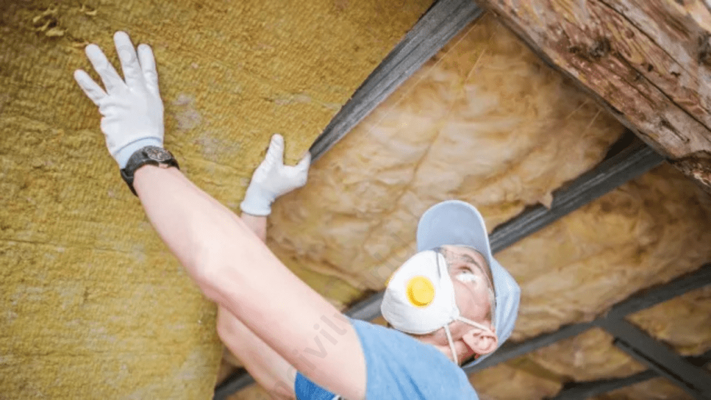
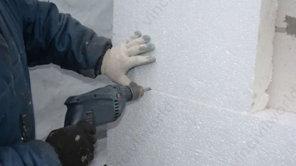
- Using a continuous thermal insulation layer, such as rigid foam board insulation in the thermal envelope.
- Lapping of insulation where direct continuity is not feasible.
- Usage of Wall assemblies with double and staggered walls.
- Using Insulating Concrete Forms (ICFs) and Structural Insulated Panels (SIPs).
- Reduce the framing factor by removing unnecessary framing members.
- Increased insulation depth by using raised heel trusses at wall-to-roof junctions.
- Installation of high-quality insulation with no voids or compressed insulation.
- Adding a gas filler and a low-emissivity coating to double or triple-pane windows.
- Installing windows with thermally broken low conductivity frames.
Keep this strategies in mind so that they can help you construct a building with zero thermal bridges. Hope you found them useful. Let’s know in the comments.
Key Takeaways
- Thermal bridging in buildings occurs where insulation is reduced or interrupted, allowing heat to flow easily.
- It can account for up to 30% of total heat loss, even in well-insulated structures.
- Thermal bridges commonly form at junctions, edges, penetrations, and structural connections.
- Major effects of thermal bridging include increased energy consumption, condensation, mould growth, and occupant discomfort.
- Thermal bridging causes often relate to poor design detailing, material choices, and construction practices.
- The main types of thermal bridging include geometric, material, structural, repeating, and point thermal bridges.
- Repeating and point thermal bridges may appear minor individually but cause significant cumulative heat loss.
- Proper identification during design is critical.
- Continuous insulation and thermal breaks reduce risks.
- Accurate detailing improves energy efficiency and building durability.
Conclusion
Thermal bridging is a critical factor that directly affects the energy efficiency, comfort, and durability of buildings. Thermal bridges in buildings and construction allow uncontrolled heat flow due to insulation gaps, material conductivity, and poor detailing. Understanding the types of thermal bridging, along with the causes of thermal bridging, enables designers and engineers to address weak points in the building envelope. The effects of thermal bridging, such as heat loss, condensation, mould growth, and increased energy costs, highlight the importance of proper planning and execution. By adopting effective strategies like continuous insulation, thermal breaks, and improved construction detailing, thermal bridging insulation issues can be significantly reduced. Addressing thermal bridging early ensures sustainable, energy-efficient, and comfortable buildings that meet modern performance standards.