Glass Fibre Reinforced Concrete or GFRC is made up of portland cement, fine aggregate, water, acrylic copolymer, alkali-resistant glass fibre, reinforcement, and additives. Glass fibre-reinforced concrete or GFRC is a type of fibre-reinforced concrete. The glass fibres used in Glass Fibre reinforcement concrete give this distinctive compound its strength. Alkali-resistant fibres serve as the primary tensile load-carrying member, while the polymer and concrete mix holds the fibres together. It assists in the transfer of load from one element to another.
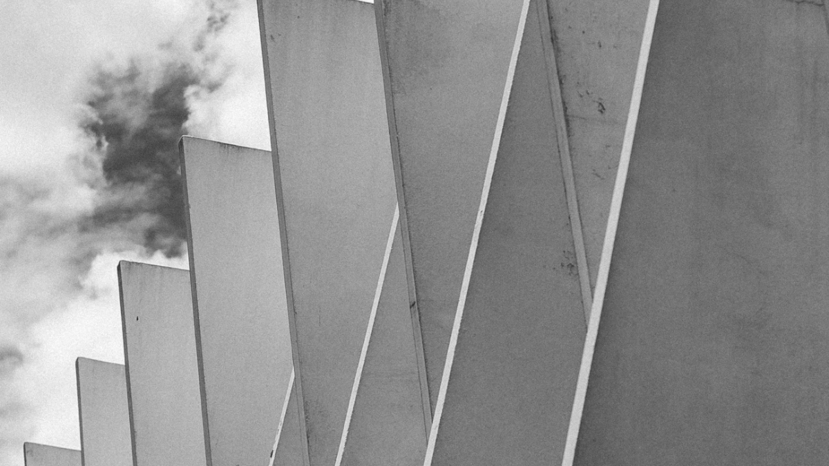
These are mainly used in exterior building façade panels and as architectural precast concrete. Somewhat similar materials are fibre cement siding and cement boards. They consist of high-strength, alkali-resistant glass fibre embedded in a concrete matrix.
In this form, both fibres and matrix retain their physical and chemical identities, while offering a synergistic combination of properties that cannot be achieved with either of the components acting alone.
Let’s get into each of them now.
- Glass Fibre Reinforcement Concrete – Ingredients
- Fibre Glass reinforced concrete – Casting Process
- Glass Fiber Reinforced Concrete Advantages
- Applications of Glass Fibre Reinforced Concrete
- Conclusions
Glass Fibre Reinforcement Concrete – Ingredients
The main ingredients used in Glass Fibre Reinforced Concrete are as follows
- Cement
- Fine aggregates
- Polymer
- Water
- Glass fibre
Related contents from vinciviworld


Cement
- Ordinary Portland cement is normally used
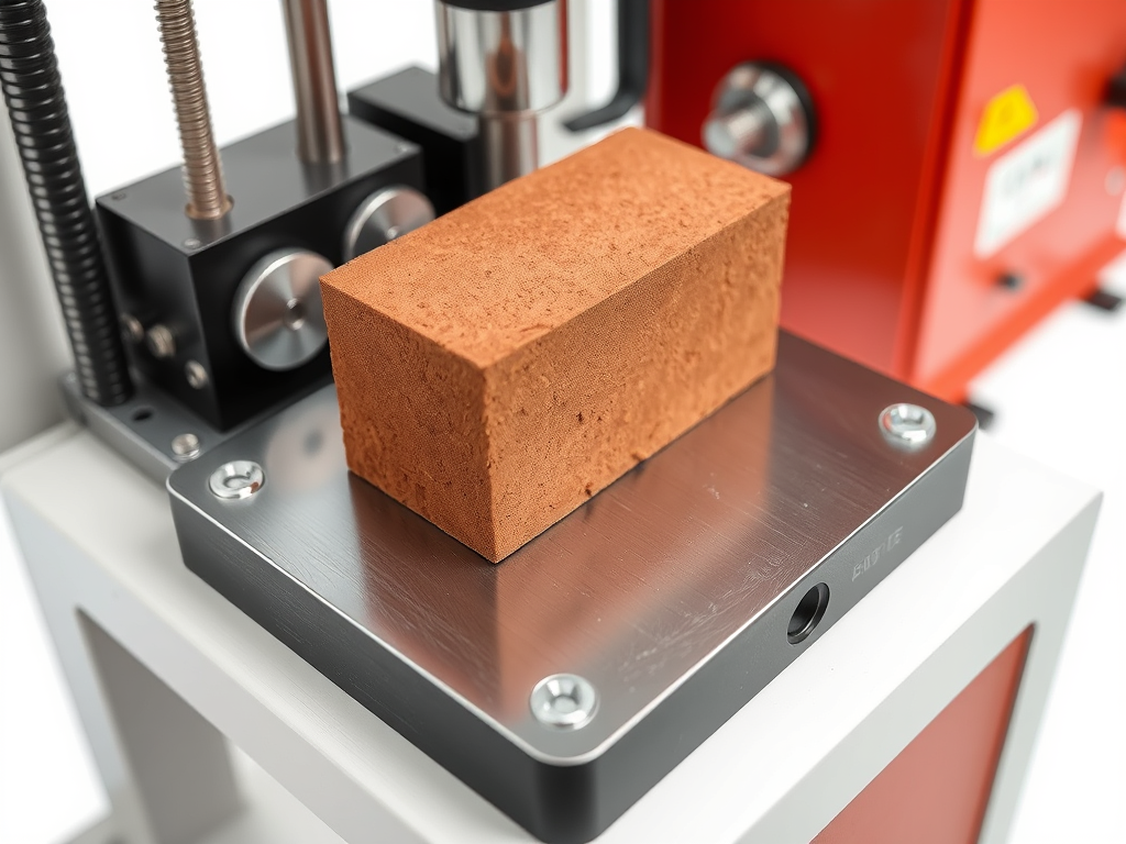
- It was tested for its physical properties in accordance with IS standards.
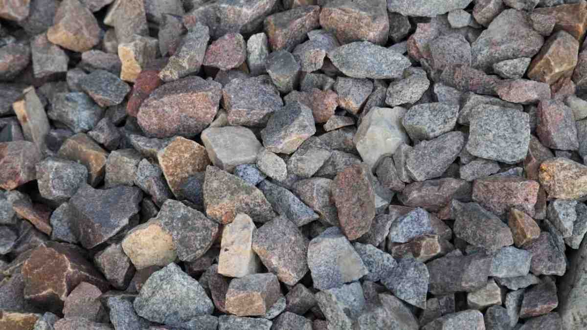
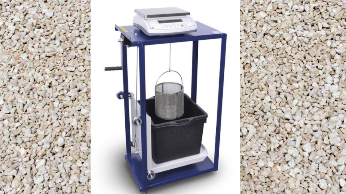
Fine Aggregates
- The fine aggregates usually should be river sand.
- The fine aggregates used passed through a 4.75mm sieve and had a specific gravity of 2.68. The fine aggregates belonged to Zone II according to IS 383. 2
Polymers
- Acrylic polymer is typically preferred over EVA or SBR polymers for GFRC. Acrylic is non-retweetable, so once dry, it will not soften or dissolve, nor will it yellow from exposure to sunlight.
- The solids content of most acrylic polymers used in GFRC ranges from 46% to over 50%.
- Typically, the polymer dose is 4%- 7% solids by weight of cementitious material depending on the design.
Water
Ordinary tap water which is safe and potable for drinking and washing was used to produce the concrete
Glass Fibre
- Glass fibre, also known as fibreglass is made from extremely fine fibres of glass.
- It is a lightweight, extremely strong and robust material. Glass fibre, the most popular of the synthetics, is chemically inert, hydrophobic, and lightweight.
- They are manufactured as continuous cylindrical monofilaments that can be cut to specific lengths or cut as films and tapes before being formed into fine fibrils with rectangular cross-sections. Glass fibres that can withstand alkalis are a crucial part of GFRC. When using the spray-up method of casting, your sprayer will automatically cut the fibres and add them to the mixture as you apply it. If you’re casting with a premix or a hybrid method, you’ll have to mix the fibres along with other ingredients.
- Although fibre content varies, it usually ranges from 3% to 7% of the total cementitious weight. High fibre content increases strength but decreases workability. Unlike most concrete mix design ingredients, fibres in GFRC are not calculated as a percentage of dry cementitious weight. Instead, they are calculated as a percentage of total weight. As a result, calculating fibre load in GFRC mix designs becomes quite complicated. Glass fibre, when used at a rate of at least 0.1 per cent by volume of concrete, reduces plastic shrinkage cracking and subsidence cracking over steel reinforcement.
Other Admixtures
- Other ingredients to consider include pozzolans (such as silica fume, metakaolin, or VCAS) and superplasticizers.
So, we dug deep into the inside of Glass fibre-reinforced concrete. Next, let me walk you through the advantages of GFRC.
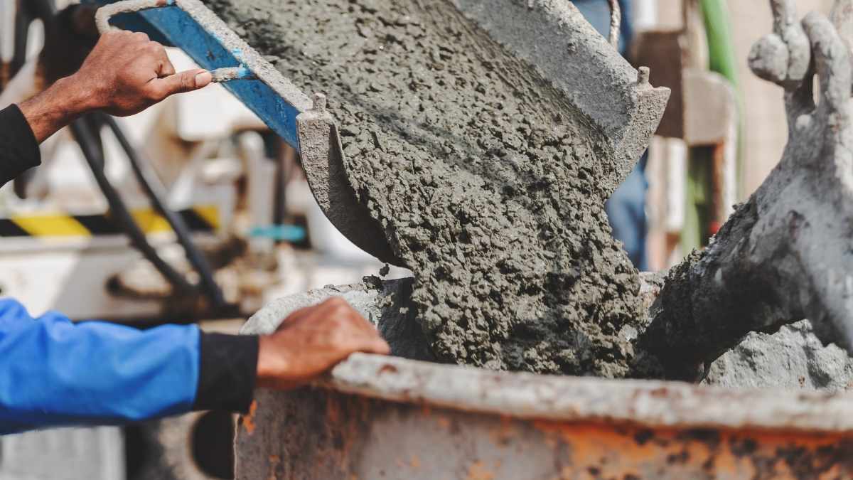
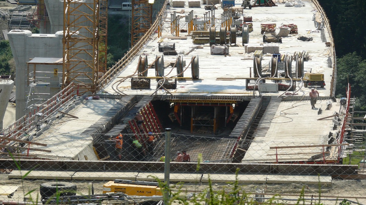
Fibre Glass reinforced concrete – Casting Process
GFRC is typically cast using two methods ie: spray up and premix. Let’s take a quick look at both, as well as a less expensive hybrid option.
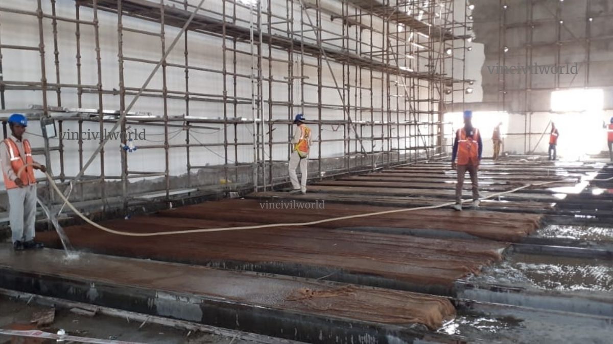
Spray-Up
The fluid concrete mixture is sprayed into the forms, similar to shotcrete. The process employs a specialised spray gun to apply the fluid concrete mixture while simultaneously cutting and spraying long glass fibres from a continuous spool. Spray-up produces very strong GFRC due to the high fibre load and long fibre length, but the equipment is very expensive.
Premix
Premix incorporates shorter fibres into the fluid concrete mixture before it is sprayed or poured into moulds. Spray guns for premix do not require a fibre chopper, but they can be very expensive. Premix has less strength than spray-up because the fibres are shorter and distributed more randomly throughout the mix. The cost and strength are comparatively lesser than the spray-up method.
Hybrid method
An inexpensive hopper gun can be used to apply the face coat while a handpicked or poured backer mix is used to create GFRC using a hybrid technique. A thin, fibre-free face (referred to as a mist coat or face coat) is sprayed into the moulds, and the backer mix is then packed in by hand or poured in, much like ordinary concrete. This is the method most concrete countertop manufacturers employ. This is an inexpensive way to get started. However, it is critical to carefully create both the face mix and the backer mix. This is to ensure similar consistency and makeup, as well as to know when to apply the backer coat. While doing so the backer coat can adhere properly to the thin mist coat without tearing it.
This method is comparatively inexpensive when compared to the r two methods. The face and backer mix are applied at different times ensure to have similar make-up of mixes to prevent curling
Glass Fiber Reinforced Concrete Advantages
The main advantages are,

Low weight and high strength of Glass Fiber Reinforced Concrete
- Self-weight of structures decreases when Glass Fiber Reinforcement Concrete (GFRC) is used and demands on foundations are reduced.
- GRC cladding is suitable even for very high-rise buildings and offers good performance under seismic loading.
Freedom of shape of Glass Fiber Reinforced Concrete
- GRC is easily moldable into a wide range of shapes, including intricate grilles, panels with a double curvature and 3-D objects.
- The high freedom of shape permits the production of structurally very efficient elements.
- Easily cast, it can produce items with very fine details and reproduce very complex features and elements of both modern and historic buildings.
3. Durability
- Basic reinforcement is non-ferrous and the GRC products are not susceptible to corrosion as in traditional reinforced concrete.
- Low permeability and a very slow rate of carbonation offer protection against the corrosion of steel in adjacent reinforced concrete.
- GFRC has an inherently high resistance to extreme exposure conditions (freeze/thaw, fire etc.)
The appearance of Glass Fiber Reinforced Concrete
- An extremely wide range of attractive surface finishes is available.
- It satisfies the highest requirements for an aesthetic appearance of new structures and is capable of matching the colour and texture of surfaces of existing buildings.
- Durable and brightly coloured surfaces with enhanced self-cleaning can be achieved in a variety of textures and shapes.
Environment
- The relatively low weight of GRC products reduces CO2 emissions associated with their transport.
- There are no Volatile_organic_compounds or other pollutants emitted from the material itself, neither in production nor in use.
- GRC is fully recyclable into concrete and other applications.
- In addition, the photocatalytic E-GRC reduces directly and significantly the concentration of pollutants in the surrounding air, leading to a better quality of the environment.
- This is good especially in congested urban centres and at a minimal additional cost.
Also read: 3 d Printing buildings |Concrete Printing & Contour Crafting Methods Full Guide
Now, how about a quick glance through the applications?
Applications of Glass Fibre Reinforced Concrete
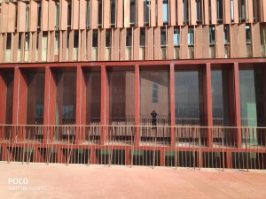
Due to its versatility the range of GFRC is growing.
- All the categories of buildings have been constructed using GFRC
- Small, simple and unsophisticated items for everyday use are made using GFRC on a large-scale
- Architects prefer GFRC to fulfil high structural complexity, size of construction elements, and freedom of shape to achieve spectacular appearance, durability and the highest quality
- Positive environmental performance
That’s it. Time to sum up.
Conclusions
- GFRC has a large scope of application and research and development is going on
- It is a very versatile material and the freedom of shape makes it the number one choice by architects
- Glass fibre reinforced concrete is used from small scale household products to large-scale buildings of structural complexity
So, how is our buddy GFRC? Let me know your thoughts in the comments.
Also read: Shotcrete – An overview| Shotcrete vs Gunite
Happy learning!