The splitting tensile strength test is performed on hardened concrete to determine its tensile strength. Marginal variations in water to cement ratio, ingredient proportioning, increase in a slump, etc impacts the desired concrete strength. This in turn affects the strength and stability of structures. There are several tests to determine the strength of concrete.
Quality tests are to be conducted on concrete at various stages starting from the production stage to the hardened stage, and on structures. Quality tests play an important role in ensuring the construction quality. This article covers splitting tensile strength test for deriving the strength of concrete
Quality tests on concrete
The Quality tests are done on different stages like production stage, hardened stage and Non destructive tests.
In this article we deal with the Splitting tensile strength test of concrete.
Splitting tensile strength test – Significance
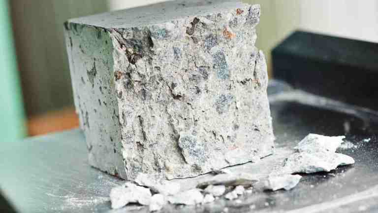
Since concrete is brittle, it is weak in tension and can cause cracks. So it is essential to conduct the tensile strength test of concrete. A method of determining the tensile strength of concrete using a cylinder which splits across the vertical diameter. It is an indirect method of testing tensile strength of concrete. At least three samples should be tested and an average value is calculated. The main objectives of this test are as follows
For determining the tensile strength of concrete.
To provide the information on the use of sand and aggregate.
To determine the uniform stress distribution.
For studying the behaviour of concrete.
Relevant code
IS 5816: 1999
ASTM C496
splitting tensile stress
Apparatus used
Testing machine
Plate or Supplementary Bearing bar
Bearing strips
Cylinder specimen
Tamping rod
The testing machine should apply continuous load without shocks. So for this test, two bearing strips with 3.2 mm thick and 25 mm wide are used. The dimension of the cylindrical specimen is 150 mm in diameter and 300 mm in height.
Splitting tensile strength
Test procedure of Splitting tensile strength test
The first step is to prepare the concrete mix for making the cylindrical specimen.
Grease the inside surface of the mould and Pour the mix into the mould as layers.
Compact each layer using a tamping rod. Tap each layer 30 times.
Uniformly stroke the concrete mix and remove the excess concrete.
Then immerse the casted specimen in water for 24 hours at 27-degree celsius.
After that remove the specimen from the mould and immerse it in freshwater.
The splitting tensile strength of concrete should be conducted at 7, 28 days of curing.
Before starting the test, take the specimen from the immersed water and wipe the water.
Then note the dimension and weight of the specimen.
Place plywood strip above and below the specimen
After that place the specimen on the testing machine.
Then gradually apply load at a rate of 0.7 to 1.4 MPa/min (1.2 to 2.4 MPa/min based on IS 5816 1999).
Record the load at which the specimen breaks.
Calculation – Splitting tensile strength test
Splitting tensile strength of concrete, T= 2P/ Ω LD
The unit of tensile strength is N/mm. The splitting test is easy to perform and we can get uniform results. It is a simple, reliable and convenient method to determine the strength of concrete.
Compressive strength of concrete is the ability of the concrete to withstand loads without cracking or deformation. Compressive Strength of concrete is defined as the Characteristic strength of 150 mm size concrete cubes @28 days. Marginal variations in water to cement ratio, ingredient proportioning, increase in a slump, etc impacts the desired concrete strength which in turn affects the strength and stability of structures.
Quality tests are to be conducted on concrete at various stages starting from the production stage to the hardened stage, and on structures. Quality tests play an important role in ensuring the quality of a particular construction. This article covers the types of tests conducted on concrete at various stages.
Quality tests on concrete
Quality tests are done on different stages as listed below,
Production stage quality tests ( On fresh concrete before placing)
This article is about compressive strength test of concrete, its significance and procedure.
Compressive strength test of concrete – significance
As a construction material, concrete should be able to withstand heavy loads. The concrete material beneath compression tends to reduce its size. Concrete gains its strength over time. The compressive strength depends on cement strength, water-cement ratio, concrete quality etc. The test gives an idea of the overall strength and above-mentioned factors. Through conducting this test, one can easily judge the concrete strength and quality of concrete produced. We can calculate the compressive strength from the failure load and the cross-sectional area of the specimen.
Concrete compressive strength for general construction varies from 15 MPa (2200 psi) to 30 MPa (4400 psi) and more than that in case of commercial, industrial structures and special structures.
The compressive strength helps in determining
Quality control
Acceptance of concrete
Evaluation of curing
For determining the in-place concrete strength.
Age of concrete, etc.
Formula for compressive strength
Compressive strength formula for any material is the load applied at the point of failure to the cross-section area of the face of the concrete specimen (cube or cylinder) on which load was applied.
Compressive Strength = Load / Cross-sectional Area
Relevant IS code
IS: 516-1959
Apparatus used
Compression testing machine or Universal testing machine
Cube or cylinder specimen
Weighing machine
Vibrating machine
Trowel
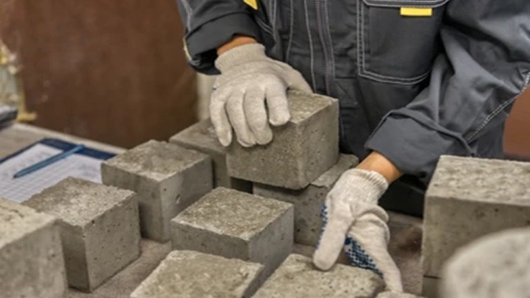
Compressive strength test of concrete
The specimen for this test can be cubic or cylindrical. The dimension of the specimens is as follows.
Cube = 150mm x 150mm x 150mm
Cylinder = 150mm diameter, 300mm height
The mould is made up of cast iron or steel. Cubical moulds are preferred for most works.
Compression testing of cubes – Procedure
Mixing of materials.
The first step is to prepare the test specimen by mixing the ingredients.
Mix the cement, coarse aggregate and fine aggregate in dry condition uniformly.
Mixing of the materials is by using batch mixer or by hand mixing.
Ingredients shall be bought to room temperature, before commencing the test.
Preparation of Test specimen
Clean the cube mould and apply the lubricant inside the mould.
Make at least three specimens from each batch.
After mixing the concrete, fill the specimen in the mould in three-layer at 50 mm thickness.
After that stroke 35 times and compact the concrete using a vibrating machine.
Then remove the excess concrete using a trowel.
After that mark the date, grade of concrete etc and immerse the specimen in freshwater.
Then store the specimen at a temperature of 27-degree Celsius for 24 hours.
Procedure for testing
The specimens should be tested using the compression testing machine at 3, 7 and 28 days.
Before starting the test take the specimen from water and remove the mould.
The test should be conducted in the wet condition of the specimen.
Record the weight and dimension.
Then place the specimen in the testing machine.
Gradually apply load on the specimen at a rate of 140 kg/ cm2 per minutes.
Note down the load at which the specimen breaks.
Compressive strength test of concrete
Calculation for Compressive strength test of concrete
The compressive strength of the concrete = Load at which the concrete breaks / Cross-sectional area of the specimen.
The compressive strength is expressed in N/mm2. The cube specimen is tested at 7, 14 & 28 days.
Calculation of compressive strength
Size of cube = 15cm x 15cm x 15cm
Area of specimen = 225 cm2
Expected maximum load = fck x area x f.s
Calculation shall be repeated for 7, and 28 days.
Results shall be furnished as average compressive strength of cube = …………… N/mm2 (7 days and 28 days)
Conclusion
The compressive strength of concrete cube gives and idea about the characteristics of concrete. With this single test we can judge the concrete quality and hence preferred for major construction works.
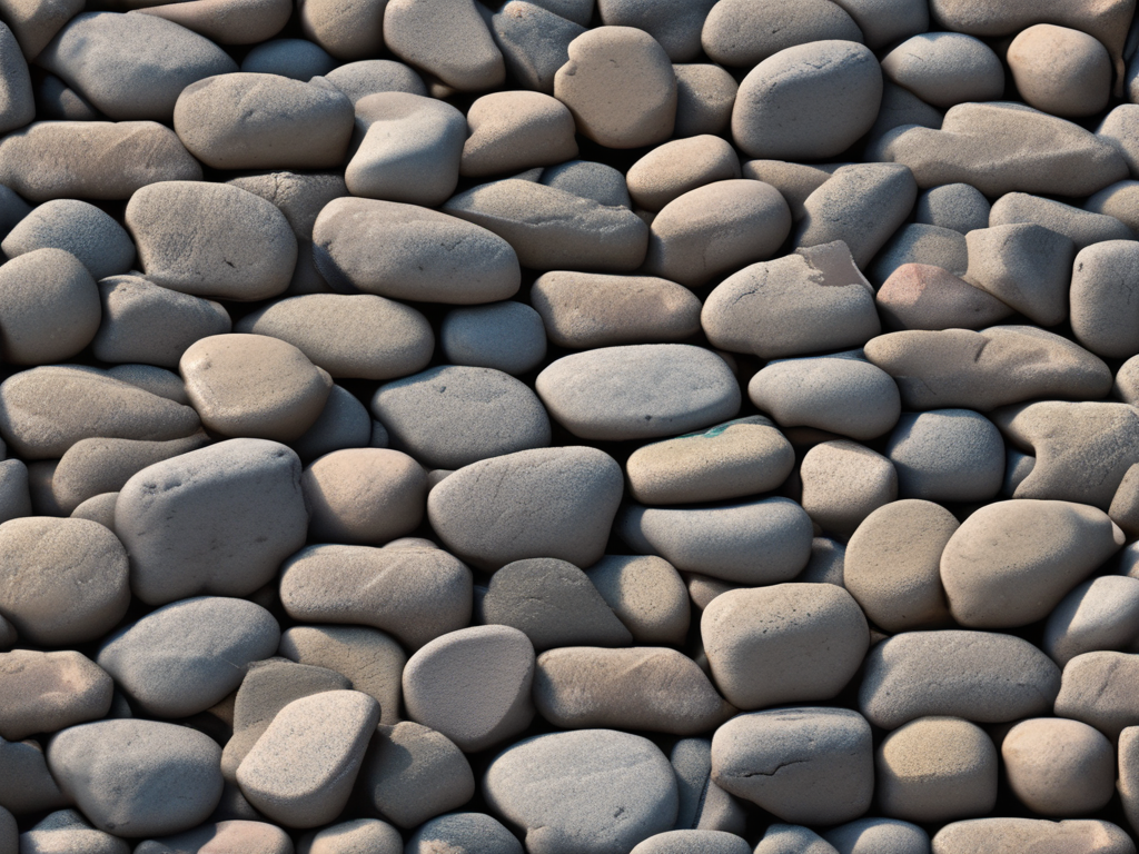
Stones are the form of rocks from the earth’s crust. They find their application in the construction of residential and public buildings, dams, harbours, face-work of structures, road metal, and railway ballast. Besides, stones have good strength and durability.
Quality tests on stones are crucial for construction projects. Testing stone ensures that it meets the necessary standards for strength and durability. There are various tests for stones that assess different properties. These tests for stones include crushing strength, water absorption, and abrasion resistance. By performing these tests, engineers can decide the suitability of the stone for specific uses. Properly testing stone helps prevent structural failures and ensures long-lasting constructions. In this blog, we will explore the different types of stones and the procedures for each quality test. This information is essential for anyone involved in construction and material choice.
Granite is a hard, durable stone, ideal for high-stress applications. Tests on stones, like crushing strength tests, highlight its robustness. Limestone is versatile but porous, requiring water absorption tests. Marble is prized for aesthetics, with abrasion resistance tests ensuring durability. Sandstone, used in paving and walls, needs strength and porosity tests. Slate, known for durability, is tested for impact resistance and is used in roofing and flooring. Proper testing stone ensures suitability for construction.
Qualities of Good Stone
We consider good-quality stones for the construction of important engineering structures. The next are the prime requirements of good-quality stones.
The heavy stones have less porosity and high compactness. Thus the specific gravity of stones should be high.
Uniform and appealing colour stones are employed for decorative works.
Should have a homogeneous composition and should have less water absorption.
It should have the ability to get good polish.
Moreover, it should be free from iron oxides and calcium carbonate to resist fire.
The dense compaction of rocks can withstand the consequences of external agencies.
A good stone must be free from quarry sap.
Test on stones
Testing stone is essential to make sure durability and strength in construction. These tests for stones assess various properties. Proper tests on stones prevent structural issues.To conclude the strength, durability and other engineering properties of the stone, the following tests are performed.
Acid test
Attrition test
Crushing test
Crystalline test
Freezing and thawing test
Hardness Test
Impact test
Water absorption test
Microscopic Test
Smith’s Test
Acid test
The acid test is a crucial procedure in testing stone for quality. Tests on stones help to determine the durability and suitability. Proper tests for stones ensure reliable construction materials.The acid tests determine the presence of calcium carbonate in rocks. The test method is as follows,
Take some 50 to 100g specimen randomly.
Then place them in the solution of sulphuric acid and hydrochloric acid having 1% strength for about one week.
Frequently mix the solution and immerse the specimen fully.
Subsequently, observe the specimen.
Specimen with high lime content causes efflorescence due to the presence of an acid solution.
Attrition test on stones
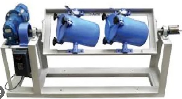
The attrition test indicates the rate of wear of the stone under the sudden impact of loads. Another name of the attrition test is the abrasion test. The apparatus for the attrition test is Devel’s testing machine.
Take some sample specimen and break them into small pieces having 60mm size.
Now take 50N of stones and place them in the cylinder of the testing machine.
Then close the cylinder and rotate them for 5 hours at a rate of 30 rpm.
After 5 hours, take the samples outside and sieve them through a 1.5 mm mesh.
Weigh the amount of material retained in the sieve and calculate the percentage of wear using the following formula.
Percentage of wear = ( Loss in weight / Initial weight ) x 100
Thus, we get the percentage of wear.
Crushing test on stones
The crushing test gives the strength of the stones. These tests are performed for stones to be used at the bottom of heavy structures.
For this test, cut the stone specimens into 40mm x40mmx 40mm and dress the sides.
Minimum of three specimens are needed for this test.
Before starting, place the specimen in water for 72 hours.
Then cover the load-bearing surface of the specimen with a plywood layer.
Now place the specimen in the testing machine.
Simultaneously, apply load axially at a rate of 13.7 N/mm2 per minute.
Note down the load at which the stone breaks. Calculate the strength using the following formula.
Crushing strength = Maximum load at which stone breaks / Loaded area
However even weak stone possess high compression strength. For example, the crushing strength of stone for ordinary building works should not exceed 1N/mm^2.
Stone Crystalline test
This test defines the weathering nature of stones. To conduct this test we need at least 4 cubes with 40mm size. The crystallisation of Calcium sulphate causes eroding of stones
To start with first, immerse the samples in a solution of sodium sulphate at normal room temperature.
After that dry them at 100 degree Celsius and repeat these steps 5 times.
Then note down their difference in weight in the percentage of the original weight.
The difference in weight shows the weathering quality of the stones.
Freezing and Thawing Test
As stones in the construction work are exposed to sunlight, wind, rain etc. This test is necessary to carefully study the behaviour of stone. The test procedure is as follows.
Take the specimen and immerse it in water for 24 hours.
Then place it in a freezing mixture at 12 degree Celsius for 24 hours.
Frequently repeat the above two steps and observe the stone quality.
Besides, perform this test only in the shade to prevent the consequences of rain, sunlight, etc.
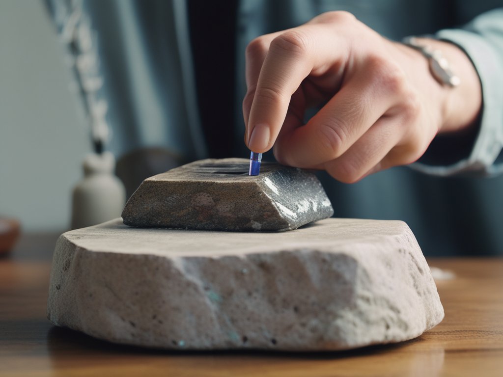
Hardness Test
The hardness of the stone is its ability to resist scratch or rebound.
For this test, we use a penknife. This can not make a scratch on pard stones like granite.
Moh’s scale value determines the hardness of the specimen.
For example, Moh’s scale value is 1. Since it is easily scratchable.
Likewise for Quartz, Moh’s scale value is 7. Since it cannot be scratched with a knife.
Impact test
The impact test determines the toughness of the stone. The impact testing machine is the apparatus used for this test. The test procedure is as follows.
Take a specimen in a cylindrical shape with 25mm diameter and 25mm height.
Then place it on the cast iron anvil of the machine
After that, allow a steel hammer of 20N to fall vertically over the specimen
The first blow height is at 1cm. For the second blow height, it is 2cm and so on.
Gradually increase the height of the blow. Finally, note down the height at which the specimen breaks.
The height at which the specimen breaks is the toughness index.
Water absorption test
Through this test, we can determine the porosity as well as moisture content. The water absorption test is as follows
Prepare a stone sample and record its weight asW1
Then immerse the cube in distilled water for 24 hours.
After that wipe the water with a damp piece of cloth. Again weigh the sample as W2.
Now suspend the cube freely in water and record its weight as W3.
Subsequently, place the cube in boiling water for five hours. Again weigh the cube and record its weight as W4.
From the above data, we can also calculate the percentage absorption of water and saturation coefficient using the formula.
Percentage absorption by weight after 24 hours = (W2- W1)/ W * 100
Percentage absorption by volume after 24 hours = (W2 – W1)/( W2 – W1) * 100
Saturation coefficient = Water absorption / Total porosity = (W2- W1) – ( W4- W1)
Microscopic tests on stones
This test helps to study the geology of the stone. The sample is placed for microscopic examination to analyse the below properties.
Mineral components
Texture and nature of stones
Presence of malicious substance
Determining defects and pores
Size calculation, etc.
Smiths tests
Smith’s test calculates indicates the presence of earth matter in stones.
In this test firstly, break the specimen into small pieces.
Then take a test tube with clear water and place these pieces in it.
Vigorously shake the test tube. The muddy colour of the water shows the presence of earthy matter.
Key Takeaways
Quality tests on stones are essential for ensuring their suitability in construction projects. Testing stone involves various tests, including crushing strength, water absorption, and abrasion resistance. Each test stone procedure is designed to assess specific properties, such as strength, durability, and weather resistance. Granite, limestone, marble, sandstone, and slate are commonly used stones that undergo these tests for stones. Procedures like the acid test, attrition test, and freezing and thawing test help determine the stone’s durability and resistance to environmental factors. Proper tests on stones prevent structural issues and ensure long-lasting constructions. Understanding these tests for stones is crucial for anyone involved in construction and material selection.
Conclusion
In conclusion, performing quality tests on stones is a fundamental step in construction to ensure the materials’ strength and durability. Testing stone through various procedures, such as crushing strength, water absorption, and impact tests, provides critical information about the stone’s properties. These tests for stones help in selecting the right material for different construction purposes, ensuring safety and longevity. Types of stones like granite, limestone, marble, sandstone, and slate each require specific testing methods. Therefore, incorporating these tests on stones into the construction process is vital for achieving reliable and robust structures. Properly testing stone materials guarantees their performance and enhances the overall quality of construction projects.
Wastewater treatment is an area where a lot of experts have carried out in-depth research. According to The United Nations World Water Development Report (WWDR), about 80% of wastewater is released into the water bodies without proper treatment on a global scale.
In the previous blog, I showed you some innovative ways to conserve water. Today we are going to dig deeper into the journey of wastewater through a wastewater treatment plant.
In the first section, let me introduce you to the wastewater treatment process.
Wastewater Treatment Process
The method of removing pollutants from wastewater or sewage and converting it into an effluent that can be added to the water cycle is known as wastewater treatment. In wastewater treatment plants, pollutants in wastewater are reduced to a degree that nature can accommodate.
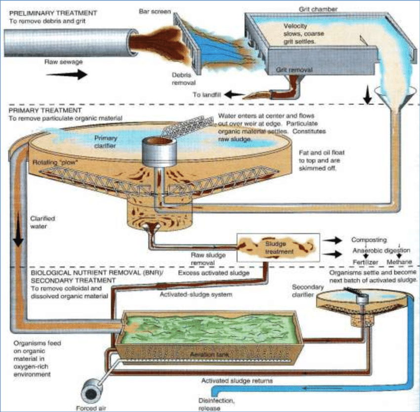
Here’s a step-by-step guide to explain what happens at each point of the treatment process and how contaminants are neutralised or removed to help keep our rivers and streams safe.
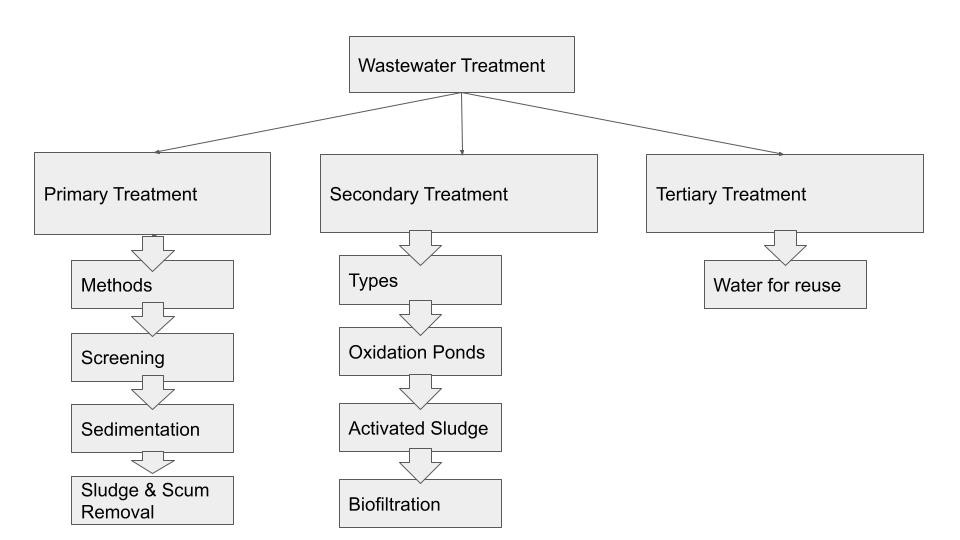
As shown in the diagram, the three main stages in the treatment of wastewater are:
Primary Treatment
Secondary Treatment
Tertiary Treatment
Let’s analyse what happens in each of the stages in detail.
Primary Treatment of Wastewater
Wastewater reaching a treatment plant through pipes first undergoes primary treatment irrespective of its source. About 60% of the suspended solids are removed from the wastewater during primary treatment along with aeration or stirring in the water to put oxygen back. It includes the following steps:
1. Screening
The majority of the floating materials are removed from the wastewater using screens of 10 mm openings and settling tanks.
The floating materials include stone, rocks, sticks and even dead animals. Solid materials make up about a third of the wastewater.
As a result, eliminating solid waste at the initial stage makes subsequent treatment procedures easier. Also, they may cause problems later in the treatment process if they are not removed.
Solid waste is collected and disposed of in landfills after the screening process.
2. Sedimentation
The sewage then flows through the grit trap or grit chamber which collects sand, cinders, and small stones at the bottom.
The wastewater is then directed to sedimentation ponds, settling tanks, or clarifiers after the settled grit have been removed.
Organic and inorganic matter, as well as suspended solids, are removed in this process.
The suspended particles begin to fall to the bottom and form a solid mass known as sludge.
3. Sludge Removal
In the sedimentation tanks, sludge (the organic solid component of the sewage) settles out of the wastewater.
Mechanical scrapers in the tank’s base continuously move accumulated sludge to a hopper, where it is pumped to sludge treatment facilities.
The thickening step removes some of the water before the sludge is processed in digesters.
4. Scum Removal
Lighter materials rise to the surface as sludge settles to the bottom of the sedimentation tanks.
Grease, oils, plastics, and soap are among the ‘scum.’
Scum is skimmed off the surface of the wastewater by slow-moving rakes.
Scum is thickened before being poured into the digesters with the sludge.
Around 90% of suspended solids, 55% of faecal coliforms, and 50% of biological oxygen demand are removed during the primary treatment process. The waste must be subjected to secondary treatment in order to be completely free of toxic substances. Let’s see how to do that.
Source: researchgate.net
Secondary Treatment of Wastewater
Secondary wastewater treatment is designed to significantly degrade the biological content of the waste by aerobic biological processes, and it operates at a deeper level than primary treatment.
During secondary wastewater treatment, about 85% of the organic matter in sewage is eliminated.
The method entails combining the wastewater with bacteria and oxygen at high pressures.
Bacteria digest organic matter with the aid of oxygen.
Secondary wastewater treatment reduces common biodegradable pollutants to acceptable levels, allowing for cleaner release into the nearby water bodies. It is done in one of three ways:
1. Biofiltration
Sand filters, contact filters, and trickling filters are used in biofiltration to ensure that any excess sediment is extracted from the wastewater.
A trickling filter consists of a bed of stones that is about 6 feet tall.
Sewage coming out of the sedimentation tank is permitted to pass through this stone sheet.
The bacteria congregate on these stones and begin to multiply and evolve until all of the organic matter in the sewage has been consumed.
Following the process, the clean water is piped out and directed to another sedimentation tank.
2. Oxidation Ponds
Oxidation ponds, also known as lagoons or stabilisation ponds, are large, shallow ponds that use the interaction of sunlight, bacteria, and algae to treat wastewater.
Algae use the sun’s energy, as well as carbon dioxide and inorganic compounds released by bacteria in the water, to grow.
During photosynthesis, algae release oxygen, which is needed by aerobic bacteria.
Mechanical aerators are often used to provide even more oxygen, reducing the size of the pond needed.
Dredging is needed to remove sludge deposits in the pond.
Filtration or a combination of chemical treatment and settling will kill any residual algae in the pond effluent.
The air and sludge are allowed to come into close contact with the bacteria during this process and then passed into the settling tank.
The sewage from the settling tank is first sent to an aeration tank, where bacteria are added to the air and sludge.
The entire setup is left alone for several hours, during which time the bacteria decompose the organic matter into toxic by-products.
The sludge, which has been activated by billions of bacteria, is returned to the aeration tank to handle fresh sewage.
The previously treated wastewater is pumped to the sedimentation tank, which filters out any bacteria.
We have seen the primary and secondary treatment of wastewater. Now it’s time to see what happens in the tertiary treatment of wastewater.
Tertiary Treatment of Wastewater
The aim of tertiary wastewater treatment is to improve the water’s quality to meet domestic and industrial standards, as well as to meet specific criteria for water discharge safety. It can be done by ion exchange, reverse osmosis, chemical precipitation, membrane filtration etc. In the case of municipally treated water, the tertiary treatment also includes the elimination of bacteria, ensuring that the water is safe to drink.
In some cases, quaternary treatment is also done. This stage deals with contamination levels of a few parts per million to billions of parts per billion, and it often includes oxidation or fine filtration.
Wastewater Treatment
Shall we wrap up?
Conclusion
Wastewater treatment refers to the purification of sewage from various sources and converting it into a reusable form. It involves mainly 3 stages namely primary, secondary and tertiary.
Primary treatment involves screening, sedimentation, sludge and scum removal. Secondary treatment deals with the removal of biological contaminants using oxidation ponds, trickling filters or activated sludge process. Finally, the Tertiary treatment converts water into a reusable form.
The management of wastewater is inextricably related to the availability of clean and adequate water sources. Far from being anything to discard or neglect, wastewater will play an important role in meeting the increasing water demand in rapidly expanding cities, improving energy production and industrial growth, and promoting sustainable agriculture.
Earthquake Engineering though not a mainstream engineering branch, is a widely researched topic now. Though all of us wouldn’t have experienced an earthquake most of us must have seen news and videos about the tremendous loss it causes. Looks scary, right? That’s exactly what makes Earthquake Engineering a subject of immense possibilities and research.
In this blog let me walk you through what is Earthquake Engineering and the relevant topics in Earthquake Engineering.
What is Earthquake Engineering?
Earthquake engineering is a branch of civil engineering that considers the impacts of earthquakes while designing and analysing engineering structures. The ultimate aim is to make such structures more earthquake resistant.
In a major earthquake, an earthquake (or seismic) engineer attempts to construct structures that will not be affected by slight shaking and will prevent significant damage or failure. Earthquake engineering is a scientific area concerned with reducing seismic risk to appropriate socioeconomic levels to protect society, the natural environment, and the built environment from earthquakes.
The main objectives of earthquake engineering include:
Anticipate the effects of powerful earthquakes on urban areas and civil infrastructure.
Design, construct and maintain structures so that they function as expected and per building codes when exposed to earthquakes.
Isn’t it amazing that a properly designed structure need not be extremely strong or costly? Instead, it just has to be carefully designed to withstand seismic forces while sustaining a minimum amount of damage. In this blog, I will show you how exactly this can be done.
Earthquake Engineering Relevant Topics
Let me give you a brief description of earthquake engineering’s relevant topics.
Seismic Performance in Earthquake Engineering
Seismic Vibration Control in Earthquake Engineering
Earthquake Engineering- Seismic Performance
The ability of a structure to maintain its key functions, such as protection and serviceability, during and after an earthquake exposure is referred to as earthquake or seismic performance. If a structure does not threaten the lives and well-being of those in or around it by partially or fully collapsing, it is considered secure.
Earthquake Engineering- Seismic Vibration Control
The term “seismic vibration control” in Earthquake Engineering refers to a range of technological methods for reducing seismic vibrations in both building and non-building structures. There are three types of seismic vibration control devices: passive, active, and hybrid.
Passive control devices have no feedback capability between them, structural elements and the ground
Active control devices incorporate real-time recording instrumentation on the ground coupled with earthquake input processing equipment and actuators inside the structure.
Hybrid control devices combine the functionality of active and passive control systems.
Due to reflections, as ground seismic waves reach up and begin to penetrate a building’s foundation, their energy flow density drops dramatically: usually by up to 90%. The residual portions of the incident waves after a major earthquake, on the other hand, also have significant destructive potential.
There are a variety of ways to monitor seismic waves once they reach a superstructure to mitigate their damaging effects and increase the building’s seismic efficiency, for example:
Dissipating wave energy within a superstructure using properly designed dampers.
To spread wave energy over a wider frequency range.
By absorbing the resonant portions of the entire wave frequencies band with mass dampers.
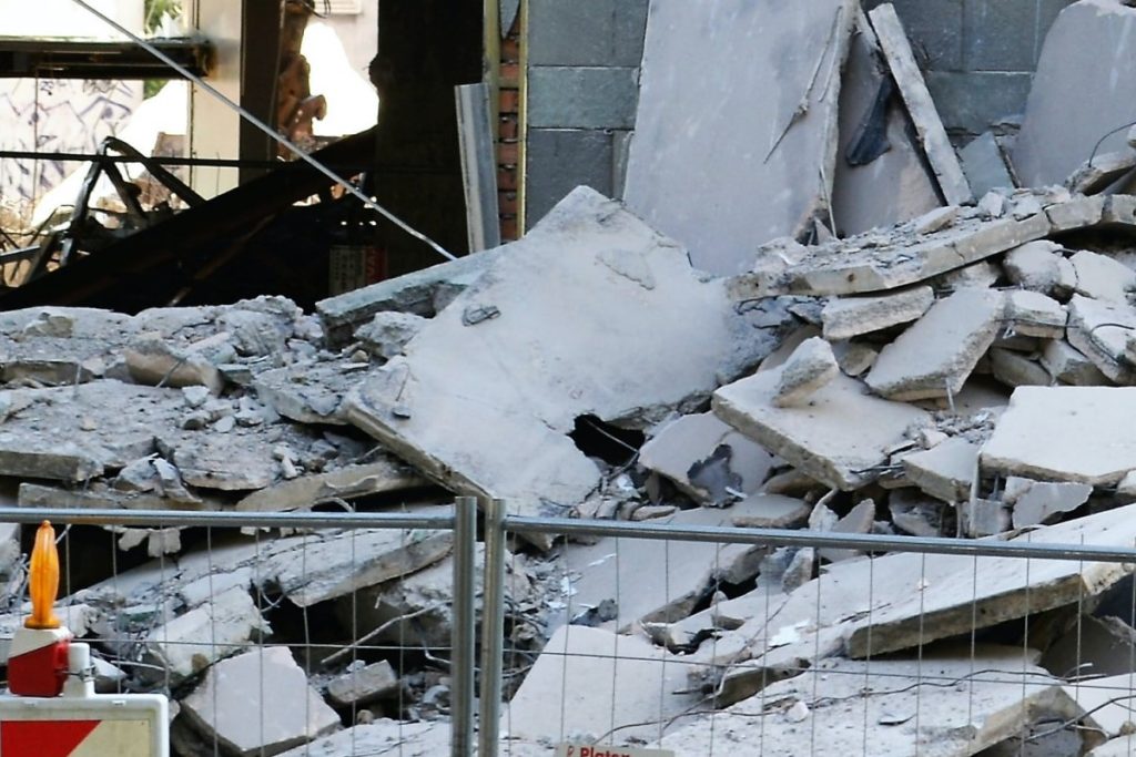
Losses due to Earthquake
Let’s see how to apply these principles in the construction field.
Earthquake Resistant Construction
Earthquake resistant construction refers to the use of seismic design to ensure that buildings and non-built structures withstand earthquakes to the best of their abilities and in accordance with relevant building codes.
Detailing of the members and their relations should be as straightforward as possible to achieve good workmanship. Earthquake design, like any other form of construction, entails the construction, retrofitting, or assembling of infrastructure using the materials available.
Adobe Structures
Timber frame structures
Light frame structures
Reinforced Masonry Structures
Reinforced concrete structures
Adobe Structures
About a third of the world’s population lives or works in Adobe structures.
Adobe mud bricks are one of the most popular and oldest building materials.
Adobe is widely used in some of the world’s most vulnerable areas, including the Indian subcontinent, and other parts of Asia.
The following are important factors to consider when improving the seismic efficiency of adobe construction:
Construction quality.
Box-like and compact layout.
Seismic reassurance.
Timber frame structures
Timber framing has been used in many parts of the world for thousands of years.
The use of timber framing in buildings provides the building’s full skeletal framing, which has structural advantages because the timber frame if properly designed, lends itself to better seismic survivability.
Timber framed structure
Light Frame Structures
Rigid plywood shear walls and wood structural panel diaphragms provide seismic resistance to light-frame structures.
For all engineered wood structures, special provisions for seismic load-resisting systems include consideration of diaphragm ratios, horizontal and vertical diaphragm shears, and connector/fastener values.
Collectors, or drag struts, are often used to distribute shear along a diaphragm length.
Reinforced masonry structures
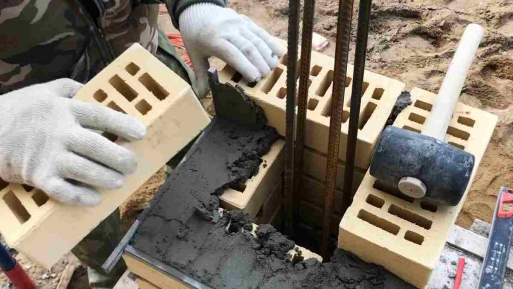
Reinforced masonry is a building method in which steel reinforcement is inserted in masonry mortar joints or put in holes and then filled with concrete or grout.
This can be achieved using a variety of methods and techniques in which the reinforced hollow unit masonry is the most common form.
The shear strength of the wall must be greater than the flexural strength to achieve ductile action in masonry.
Reinforced Masonry structures
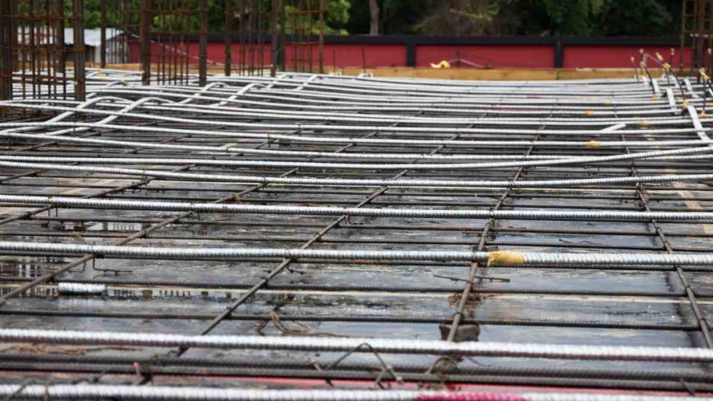
Reinforced concrete structures
Steel reinforcement bars (rebars) or fibres are inserted into reinforced concrete to strengthen a brittle composite. It can be used to make beams, columns, floors, and bridges, among other things.
Prestressed concrete is a form of reinforced concrete that is used to overcome the natural weakness of concrete in strain. It can be used for beams, floors, and bridges with longer spans than ordinary reinforced concrete allows.
Post Tension – slabs
Prestressing tendons are used to apply a clamping load to the concrete compression member, resulting in compressive stress that compensates for the tensile stress that would otherwise be applied by a bending load. A typical reinforced concrete frame should have ductile joints to avoid catastrophic failure in response to earth-shaking.
Now you have seen the basic aspects of Earthquake Engineering. How do you feel about it? Let’s know in comments.
Green Airport has been in the news for quite some time as more and more airports are going green. According to studies by ATAG, the global aviation industry produces 2% of all anthropogenic carbon dioxide emissions. When it comes to climate change, the aviation industry is under increasing pressure to clean up its act, but gas-guzzling planes aren’t the only culprits.
As airports grow, so does their carbon footprint and emissions. As new terminals, ground transportation vehicles, and facilities are built, the energy demand increases.
As a result, many airports around the world have incorporated greener elements into their designs and operations strategies, as well as pledged to support environmentally sustainable initiatives thereby transforming into green airports. Before we dig into the details about various green airports around the globe I will show you what exactly a green airport is.
What is the Green Airport concept?
Green airport is an airport that complies with the latest sustainability criteria, reduces the effects of airport activities on the environment, and mitigates the impact of climate change on related facilities and operations.
In this blog let me take you on a trip to various green airports in the world and we will analyse the key features that make each one a green airport.
Green Airports in the world
A number of airports around the world have begun to implement “green” programmes in order to make their buildings greener and more environmentally friendly. Here are 5 such airports that have earned international recognition for their sustainable and green initiatives.
Its Terminal A has heat-reflective roofing and pavement surfaces, as well as water-saving low-flow bathroom fixtures.
One of the airport’s runways was resurfaced with environmentally friendly asphalt that could be heated at a lower temperature during the construction process which would result in a 2,000t reduction in carbon emissions over the lifetime of the project.
The airport’s offices are topped with a fleet of 6ft tall wind turbines that generate about 3% of the energy required for operations.
Seems like Boston Airport is pacing really fast towards being a green airport, right? Let’s look at the other ones which are turning into green airports.
2. Galapagos Ecological Airport, Galapagos Islands – World’s first completely Green Airport.
Built to operate entirely on solar and wind energy, with windmills providing 65% of total energy and photovoltaic panels on walkways providing 35%
Steel pipes taken from oil extraction fields were used to build 80% of the infrastructure.
Wood and metal structures from the airport’s previous home, Seymour, were reused, and furniture was made with environmentally friendly materials.
A desalination plant is also present at the airport, which collects seawater and purifies it for use in the terminal.
The wastewater is then pumped back into the treatment facility for future use by travellers.
Green Airport
3. Singapore Changi Airport, Singapore
Singapore’s Changi Airport is not only one of the best in the world, but it also has a reputation for being environmentally friendly.
With skylights to enhance natural light, air conditioners located closer to the floor, and an abundance of greenery.
The recently opened Terminal 4 features a green wall with over 20,000 plant species, which lowers the temperature of the airport and increase air quality.
Energy-efficient motion sensors and lighting, water-efficient fittings, and roof-mounted solar panels are among the other features installed at Changi.
4. Stockholm Arlanda Airport, Sweden- First Green Airport to achieve carbon neutrality
The only airport in the world with an environmental permit that includes a limit on carbon dioxide emissions.
In this green airport, hangars and airfield buildings are heated with a special biofuel system to conserve energy.
A collection of wells connected to an underground aquifer collect water and sends it to the terminal’s air conditioning system in the summer.
This approach is often used to heat cement pads near the airport’s hangars, preventing ice from forming on the doors and ramps.
5. Delhi Indira Gandhi Airport, India
The 5.4 million-square-foot Terminal 3 at the airport features well-lit departure lounges, 1,200 low-power LCD displays, 300 rainwater harvesting stations, and erosion-control storm drains.
Passengers are transported between terminals and baggage claim using battery-powered vehicles.
Indira Gandhi Airport recently received two awards for its environmental stewardship,
Wings India Award for the ‘Most Sustainable and Green Airport,’
ACI’s designation as the world’s best airport with over 40 million passengers a year.
Through this blog, we have taken a closer look at some green airports that are setting a precedent for other aviation hubs to emulate by sustainable practices and the use of renewable fuel sources. What do you think of these features and what other energy-saving measures and sustainable practices can be adopted to uplift our airports to the status of a green airport? Let me know in the comments.