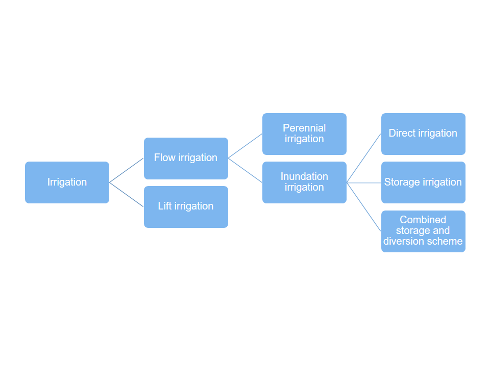
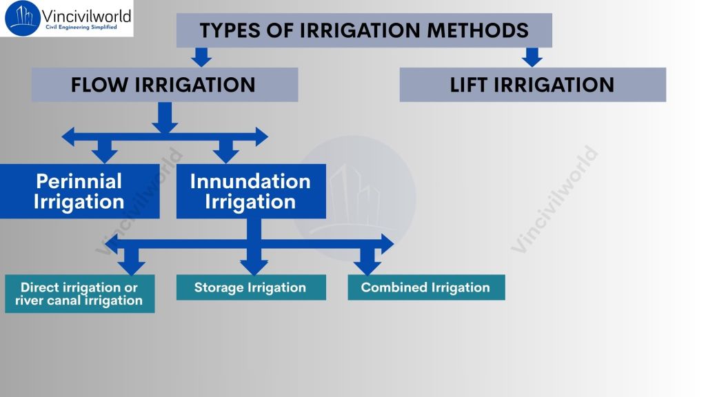
Types of irrigation are mainly divided into two- Lift irrigation and flow irrigation. Flow irrigation is further divided into perennial and inundation irrigation. Inundation irrigation is again subdivided into three. They are direct irrigation, storage irrigation and combined System. We are going to meet the huge family in the blog.
Irrigation is crucial for sustainable agriculture, ensuring crops receive water even when rainfall is uncertain. Two predominant systems are widely implemented today: flow irrigation and lift irrigation. In flow irrigation, water naturally moves from rivers or canals to fields by gravity. This includes inundation irrigation and perennial irrigation methods. These methods make it cost-effective and widely accessible. On the other hand, lift irrigation uses pumps or other means to raise water from lower sources. It offers solutions in areas where gravity canals can’t reach. Understanding the difference between lift irrigation and flow irrigation, the mechanics behind a flow irrigation system. This article covers all aspects, helping farmers and professionals choose the right irrigation strategy for their fields.
- Types of Irrigation methods
- Flow irrigation- Major among types of irrigation
- Lift irrigation- second among types of irrigation
- Choice between types of irrigation
- Difference between Lift irrigation and Flow irrigation
- Key takeaways
- Conclusion
Types of Irrigation methods
Irrigation is crucial for ensuring crops receive adequate water when rainfall is lacking. Various irrigation methods have been developed to deliver water efficiently to fields. Each method is designed to suit different landscapes. These methods also consider diverse water sources and agricultural requirements.
Irrigation is mainly two types.
- Flow irrigation
- Lift irrigation
The figure below is a schematic diagram showing the types of irrigation.
Let’s get into each of them in detail.
Flow irrigation- Major among types of irrigation
Flow irrigation is that type of irrigation in which the supply of irrigation water available is at such a level that it is conveyed on to the land by the gravity flow. The Flow irrigation is an irrigation method where water supply is conveyed to agricultural fields by gravity flow from sources like rivers or canals, without external energy. It includes perennial irrigation and inundation irrigation, making it cost-effective and widely used. Understanding flow irrigation systems and its difference with lift irrigation is crucial for efficient water management.
- Perennial irrigation system
- Inundation or flood irrigation system
So, what are these? Relax. We will take one at a time and learn.
Perennial irrigation system
In perennial irrigation system, the water required for irrigation is supplied in accordance with the crop requirements throughout the crop storage. Weirs or barrages are required to store the excess water during floods and release it to the crops as and when it is required.
The perennial irrigation system supplies water continuously throughout the crop’s growth period, matching irrigation to crop needs. It uses storage structures like dams, barrages, or weirs to store excess water during floods and releases it as required. This system ensures reliable water availability year-round; consequently, it promotes steady crop growth and higher yields. Moreover, it is particularly suitable for areas with consistent water sources.
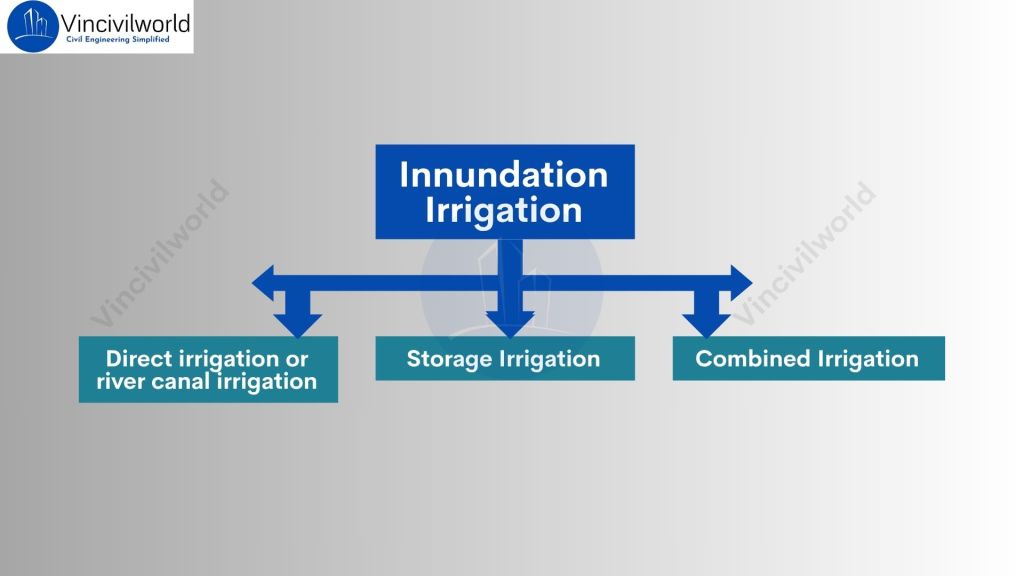
Inundation irrigation
Inundation irrigation is carried out by deep flooding and thorough saturation of the land to be cultivated which is then drained off prior to the planting of the crop.
The Inundation irrigation is a traditional method. Floodwater from a river overflow during the rainy season is diverted to agricultural land through a canal. This process occurs without any regulating structure. The canal’s bed level is fixed so water flows only when the river level exceeds it, and irrigation stops when the water level falls. Because there is no head regulator, over-irrigation may damage crops. It relies solely on gravity and natural flooding events for water supply.
Depending upon the source from which the water is drawn, inundation irrigation can be further subdivided into 3 types.
- Direct irrigation or river canal irrigation
- Storage irrigation
- Combined System
Now, what? Let’s peep into each of them to make friends with them.
Direct irrigation or river canal irrigation
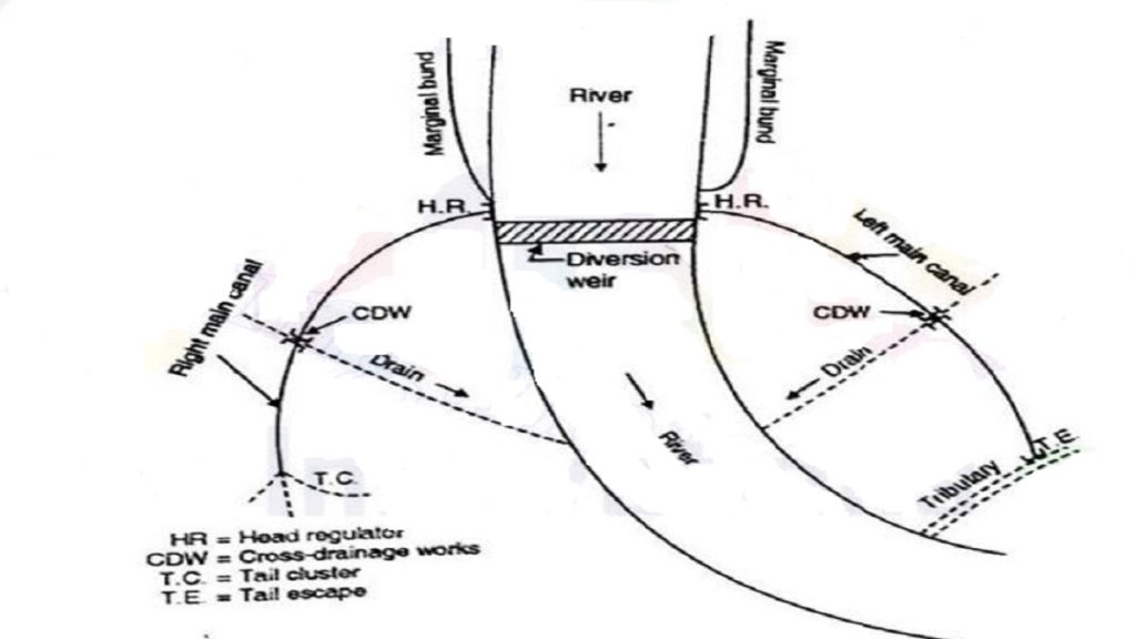
We are going to jump right into the details of direct irrigation now.
- In this direct irrigation system, water is directly diverted to the canal without attempting to store the water. For such a system, a low diversion weir or diversion barrage is constructed across the river.
- This raises the water level in the river and thus diverts the water to the canal taking off upstream of the weir, as shown in figure.
- Generally, a direct irrigation scheme is of a smaller magnitude, since there are no rigid controls over the supplies. One or two main canals may take off directly from the river.
- Cross- drainage works are constructed wherever natural drains or distributary streams cross the canals. In a bigger scheme, there may be branch canal taking off from the main canal
Learnt about direct irrigation, right? Let’s move on to storage irrigation next.
Storage irrigation
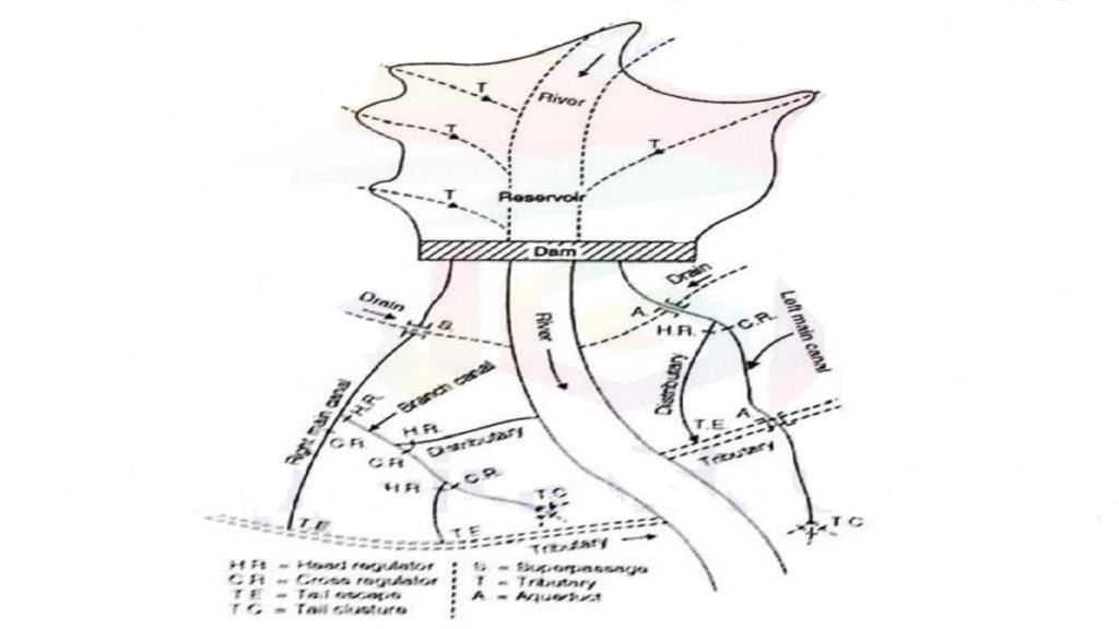
What are we waiting for? See the basic knowledge about storage irrigation now.
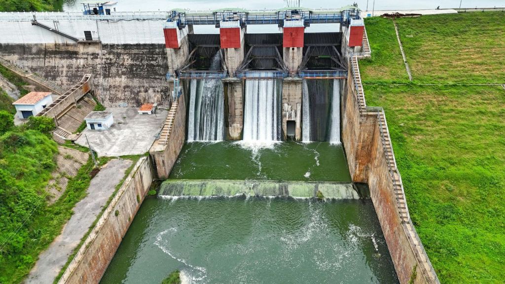
- In storage irrigation system, a solid barrier, such as a dam or a storage Weir is constructed across the river and water is stored in the reservoir or lake so formed.
- Depending upon the water requirements of crops, or the hydroelectric power generation, and upon the flow of water in the basin at the site construction, the elevation storage curve for the reservoir is known.
- The height of the dam is then decided from this curve, corresponding to the storage- volume required.
- Storage irrigation scheme is comparatively of a bigger magnitude, and involves much more expenditure than a direct irrigation scheme.
- One or two main canals take off from the reservoir. Due to the formation reservoir, some land property may be submerged to the upstream of the dam.
- A network of canal system convey water to the agricultural fields, through various regulatory works.
- Cross-drainage works such as aqueducts, syphon aqueducts, super passages and canal syphons are constructed wherever natural drains cross the canals
Time to meet the last member in flow irrigation system. Who’s that? Of course, combined system.
MUST READ: Concept of Green Building- 4 comprehensive concepts easy read!
Combined System
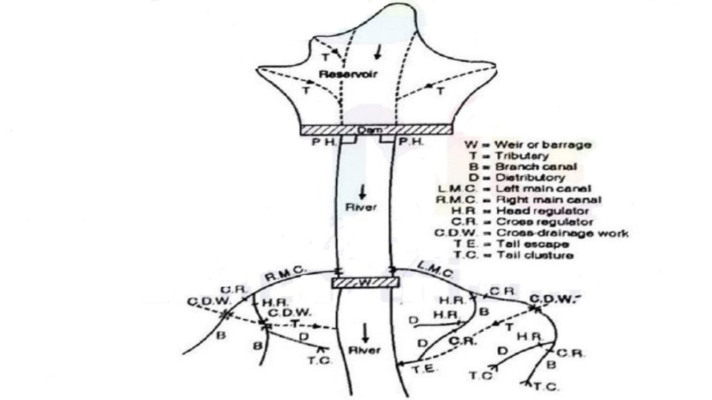
We have seen that in the storage irrigation system, water is stored in the reservoir, since the river is not perennial, while in the direct irrigation system, the river is perennial and hence the water is diverted from the river to the canal.
Sometimes, a combined scheme is adopted in which the water is first stored in the reservoir formed at the upstream side of the dam, and this water is used for water power generation.
The discharge from the power house is fed back into the river, to the downstream side of the dam. Thus, sufficient quantity of flow is again available in the river.
At a suitable location in the downstream, a pick up weir is constructed. This weir diverts the water from the river to the canal.
How can we leave the second main among the types of irrigation alone? Shake your hands with lift irrigation now.
Lift irrigation- second among types of irrigation
Lift irrigation is practiced when the water- supply is at too low a level to run by gravitation on to the land.
In this irrigation method, water is mechanically lifted from a lower-level source. It can be a river, well, or canal. The water is then moved to higher elevation fields using pumps or other lifting devices. Unlike gravity-fed systems, pumps carry the water first to a main delivery chamber. This chamber is at the highest point of the command area. From there, water is distributed by gravity through pipelines or canals to agricultural lands. The system is designed around topography, often dividing fields into blocks for fair water allocation. Lift irrigation is energy-intensive. It requires careful planning for distribution. However, it enables irrigation in areas lacking natural gravity flow. It expands cultivable zones and improves water access.
In such a circumstances water is lifted by mechanical means. Irrigation from wells is an example of lift irrigation, in which sub- soil water is lifted up to the surface and is then conveyed to the agricultural fields.
Now that you know all types of irrigation, how do you choose the right one for your requirement?
Choice between types of irrigation
Direct irrigation scheme is adopted in the circumstances where the river is perennial and has a normal flow throughout the irrigation season, never less at any time than the requirements of the field.
On the contrary, storage irrigation system is adopted when the river flow is either not perennial, or where flow is insufficient during certain parts of the crop season for irrigation requirements.
In a multistage river valley development, a combined storage- cum diversion scheme is more useful.
Difference between Lift irrigation and Flow irrigation
| Aspect | Flow Irrigation | Lift Irrigation |
|---|---|---|
| Water Movement | Water flows by natural gravity from higher to lower levels. | Water is mechanically lifted from lower to higher elevations. |
| Energy Requirement | Minimal; uses gravity, no pumps needed. | High; requires pumps and energy (electric, diesel, solar). |
| Terrain Suitability | Suitable for sloping or river command areas. | Suitable for flat or elevated lands without gravity flow. |
| Infrastructure Cost | High initial costs due to hydraulic structures (dams, canals). | Lower initial cost; no large hydraulic structures needed. |
| Operational Cost | Relatively low maintenance and energy costs. | Higher energy and maintenance costs due to pumping. |
| Water Losses | Higher losses from seepage and evaporation in open canals. | Lower losses due to closed pipelines after lifting. |
| Water Control | Less precise; depends on natural flow and canal design. | More precise; water delivery controlled via pumps/valves. |
| Complexity | Simple and economical system. | More complex, needs technical operation and monitoring. |
| Examples | Perennial and inundation irrigation. | Pumping from wells, rivers, or canals to irrigate highlands. |
This table highlights the core differences in mechanics, cost, terrain applicability, and water management between the two. Lift irrigation offers flexibility for challenging terrains. However, it incurs higher energy and operational costs. Flow irrigation relies on natural gravity. It is typically simpler but limited by topography.
Key takeaways
- Irrigation is vital for sustainable agriculture, ensuring crops receive sufficient water regardless of rainfall variability.
- Irrigation types mainly divide into Flow Irrigation and Lift Irrigation.
- Flow irrigation uses natural gravity flow from sources like rivers or canals. It encompasses perennial irrigation (continuous supply) and inundation irrigation (seasonal flooding).
- Inundation irrigation subdivides into direct irrigation, storage irrigation, and combined systems, depending on water source and storage method.
- Lift irrigation mechanically raises water using pumps to higher elevation fields, then distributes it by gravity, enabling irrigation on otherwise unreachable terrain.
- Flow irrigation is cost-effective, energy-efficient, and suited for sloping lands with reliable water sources.
- Lift irrigation offers flexibility on flat or elevated land but requires energy and technical management.
- Understanding the difference between lift irrigation and flow irrigation helps farmers choose the best system based on topography, water availability, and cost.
Conclusion
Irrigation systems are essential tools for stabilizing agricultural production and managing water resources efficiently. Flow irrigation, relying on gravity-fed water movement, remains the predominant method due to its low energy requirements and suitability for perennial and seasonal water availability. Its subdivision into perennial and inundation irrigation allows adaptation to various water flow conditions. In contrast, lift irrigation addresses challenges in flat or elevated terrains where gravity flow is impossible, mechanically lifting water to irrigate diverse lands. While lift irrigation demands higher operational costs and technical expertise, it significantly expands cultivable areas. Choosing the appropriate irrigation system depends on landscape, water source reliability, infrastructure capacity, and crop requirements. Understanding these distinctions empowers farmers and water managers to optimize irrigation efficiency, conserve water, and sustain agricultural productivity under changing climatic and geographic conditions.
MUST READ: Innovative Water Conservation Methods Unlocked.
So, loved the article on types of irrigation? Let me know if i missed out anything in the comments.