The Heat of Hydration of Cement plays a major role in determining concrete temperature, early strength, and long-term stability. The heat of hydration is the heat liberated from the reaction between cement and water. When water combines with cement compounds, it triggers the Cement Hydration Process, releasing heat that varies across different Hydration Stages of Cement. These stages influence setting behaviour, strength formation, and temperature rise in both normal and mass concrete. Understanding the Factors Affecting Heat of Hydration is crucial. Factors such as cement composition, fineness, water-cement ratio, and environmental conditions help engineers control excessive heat generation. This control helps avoid thermal cracking. In large pours like dams and raft foundations, Low Heat Cement Applications become essential to manage temperature gradients and ensure structural durability. By studying these principles, professionals can produce safer, stronger, and long-lasting concrete structures.
This article covers the Heat of Hydration of Cement and the Cement Hydration Process. It also details the Hydration Stages of Cement. Additionally, it discusses Factors Affecting Heat of Hydration and Low Heat Cement Applications.
- Tests on Cement (Field Tests and Lab Tests)
- What is heat of hydration?
- Hydration stages of cement
- Relevant Codes for measuring Heat of hydration
- Heat of Hydration test as per IS 11209
- Heat of hydration as per ASTM
- Factors Affecting Heat of Hydration
- Conclusion
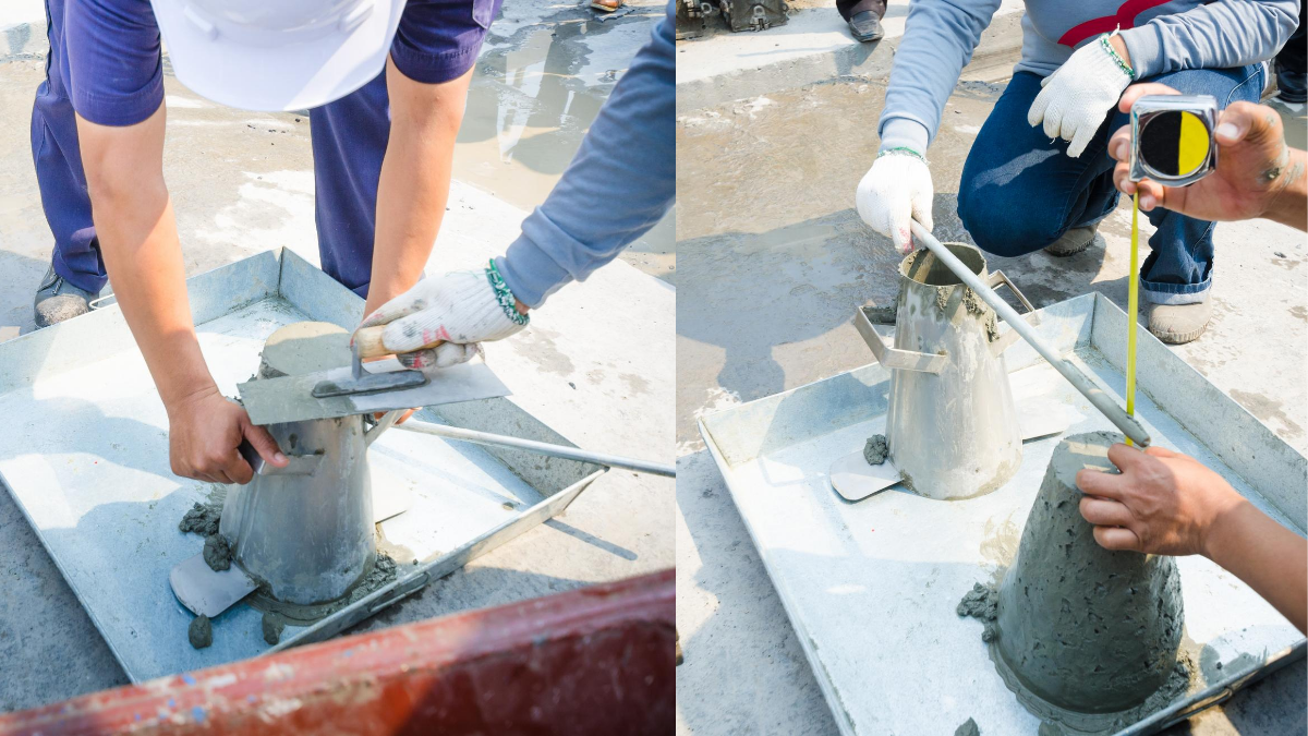
Tests on Cement (Field Tests and Lab Tests)
Tests on cement play a vital role in ensuring its quality, consistency, and suitability for construction. Field tests offer quick assessments of basic properties like colour, smoothness, and physical behaviour, helping engineers make immediate decisions on-site. Laboratory tests, conducted under controlled conditions, provide accurate information about cement’s strength, setting characteristics, durability, and chemical performance. Together, field tests and lab tests ensure that only high-quality cement is used in concrete production.
- Field tests for cement
- Laboratory tests
Field tests on Cement
Simple field tests quickly indicate cement quality without advanced equipment. By checking colour, smoothness, and basic behaviour, we can immediately judge whether the cement should be accepted or rejected.
- Checking manufacturing date
- Visual checking of lumps
- Feel test
- Heat of cement
- colour
- Water float test
- Setting test
These basic tests give an approximate characteristic of cement. These are easy and quick but not accurate, however help in concluding the acceptance of cement for works. For more details about field tests you can go through our earlier article
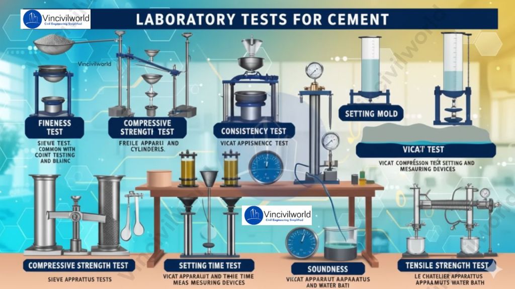
Laboratory tests for Cement
The laboratory tests define the physical and chemical properties of cement. So it is not possible to check all the cement properties at the site. Laboratory tests on concrete offer accurate evaluations of strength, durability, and physical properties. These tests help engineers verify performance and ensure quality. They also predict the long-term behaviour of structural concrete. The main laboratory tests conducted on cement is as follows.
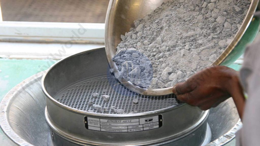
- Fineness Test
- Compressive Strength Test
- Consistency Test on cement
- Setting time
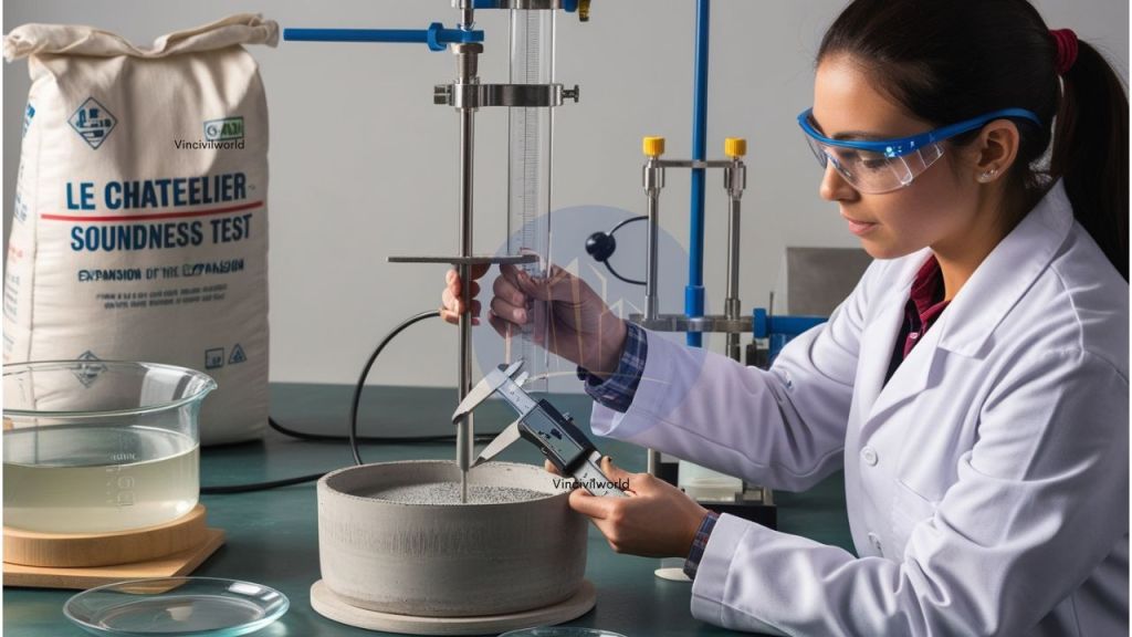
- Soundness Test
- Tensile strength Test
- Heat of hydration
Lab tests require time. But it provides accurate results.
What is heat of hydration?
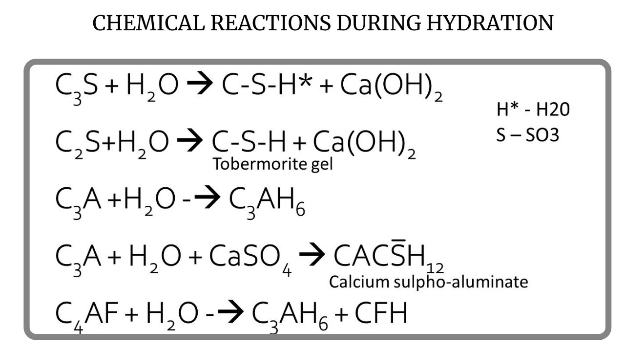
Cement contains several key chemical compounds that govern its setting and hardening behaviour. These major compounds—Alite (C3S), Belite (C2S), Celite (C3A), and Felite (C4AF)—are collectively known as the Bogue compounds, formed during the clinkering stage of cement production. Although these compounds remain inactive in dry form, they react vigorously when water is added, initiating the hydration process. Hydration is an exothermic chemical reaction, meaning it releases a considerable amount of heat as the compounds dissolve and form new binding products.

Typically, cement hydration liberates about 89–90 cal/g of heat within the first seven days and 90–100 cal/g by 28 days. The physical properties and overall performance of cement depend greatly on the rate and completeness of this hydration reaction; inadequate hydration can lead to reduced strength and long-term structural deterioration. The key chemical compounds responsible for hydration include the primary Bogue constituents listed below.
- Tricalcium silicate, C3S
- Dicalcium silicate, C2S
- Tricalcium aluminate, C3A
- Tetracalcium aluminoferrite, C4AF
- Gypsum, CSH2
This heat is highly important in concrete engineering because it influences setting time, early-age strength, and temperature rise in both thin and massive concrete elements. Properly understanding the Factors Affecting Heat of Hydration helps engineers prevent thermal cracking and select suitable Low Heat Cement Applications for large pours, dams, and raft foundation
Hydration stages of cement
The hydration stages of cement detail the progression of chemical reactions after adding water. This process influences heat release, setting behaviour, and the long-term strength development of concrete.
Initial Reaction
The hydration process begins instantly when water meets cement. During this stage, a rapid chemical reaction occurs on the surface of the cement particles. It is intense and releases a sudden burst of heat. This reaction is short-lived but crucial, as it triggers the formation of early hydration products and initiates the overall setting process.
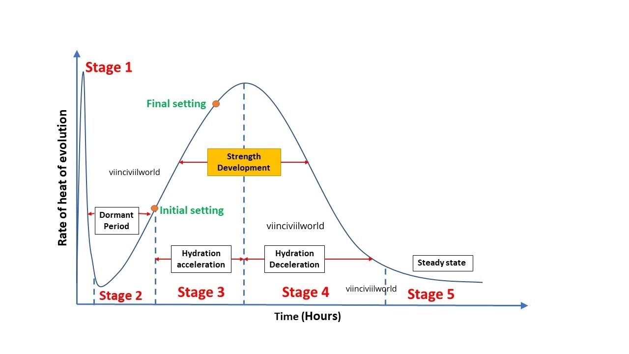
Dormant / Induction Period
After the initial reaction, the hydration activity slows down significantly and enters the dormant or induction period. This phase typically lasts 2 to 5 hours, during which the concrete remains workable and can be transported, placed, and compacted. Although the reaction rate is low, hydration continues slowly around the nuclei of the cement grains.
Acceleration Period
The acceleration stage marks a sharp increase in hydration activity. During this phase, major binding compounds such as Tobermorite gel (C-S-H gel), calcium hydroxide, and other minor products form rapidly. These substances begin depositing around the outer surface of partially hydrated cement grains, contributing to strength development.
Deceleration Stage
As the hydration layer thickens, the reaction rate begins to decrease, marking the deceleration stage. The reduced speed occurs because the growing C-S-H gel creates a barrier that slows further water penetration into the cement particles. Strength continues to develop but at a slower pace.
Steady-State of cement Hydration process
In the final stage, hydration proceeds very slowly over days, months, and even years. The reaction gradually stops once the cement particles are fully hydrated. By this time, Tobermorite gel occupies nearly 50–60% of the volume of the hydrated cement, making it the dominant contributor to long-term strength and durability.
Relevant Codes for measuring Heat of hydration
Indian Standards (IS)
- IS 11209 – Method for Determining Heat of Hydration of Hydraulic Cement
- IS 269 – Specification for Ordinary Portland Cement (includes heat categories)
ASTM Standards (USA)
- ASTM C1702 – Heat of Hydration of Hydraulic Cement (Isothermal Calorimetry)
- ASTM C1753 – Evaluating Heat of Hydration in Adiabatic Conditions
- ASTM C150 – Standard Specification for Portland Cement (heat limits)
European Standards (EN)
- EN 196-9 – Heat of Hydration by Isothermal Conduction Calorimetry
- EN 197-1 – European Cement Specification (heat classes)
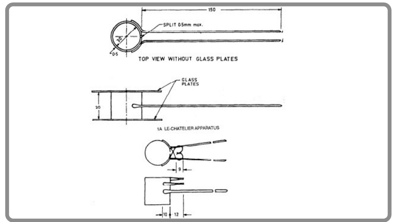
Heat of Hydration test as per IS 11209
The heat of hydration test is conducted at a standard room temperature of 27 degrees celsius. The apparatus for this test is
- Calorimeter
- Mortar and pestle
- Glass/Plastic vials
- Stopwatch or timer
- Sieve
- Muffle furnace
- Weighing balance

Heat of hydration test
The calorimeter determines the heat of the paste. Glass vial has a dimension of 80×20 mm. Muffle furnace maintains the temperature. Before performing the test, the calorimeter temperature is to be made uniform. The heat of hydration should be determined at the 7th and 28 days.
Procedure for heat of hydration test
- To find the heat of hydration, firstly we have to measure the heat released from the unhydrated cement using a calorimeter.
- Then we have to measure the heat of hydration from hydrated cement
- For that take 60 grams of cement and add 24 ml of water.
- Then fill this mixture in three glasses and seal them with wax to avoid the entry of air.
- The standard temperature should be 27 degrees celsius.
- Then measure the heat of the solution using a calorimeter.
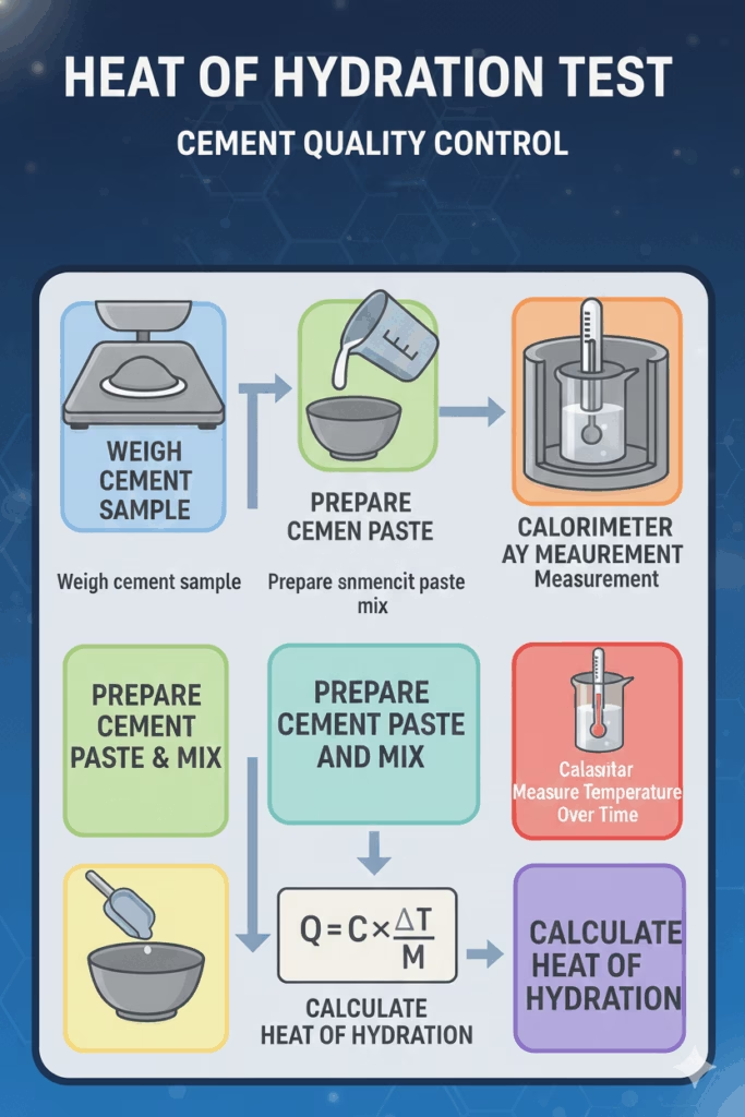
Heat of hydration = Heat released from hydrated cement – Heat released from unhydrated cement
For low heat cement, The heat of hydration for 7 days should not be greater than 66 cal/g and for 28 days should not be greater than 75 cal/gm.
Heat of hydration as per ASTM
ASTM methods measure the Heat of Hydration using precise isothermal calorimetry, providing accurate data on cement’s heat release, hydration behaviour, and performance in concrete.
Apparatus Required
- Isothermal calorimeter (high-precision)
- Sample ampoules or containers
- Precision weighing balance
- Thermometric sensors
- Mixing tools
- Temperature-controlled environment
- Distilled water
- Data acquisition system or software
Test Procedure (ASTM C1702)
- Weigh the required mass of cement sample accurately.
- Place the sample in the calorimeter ampoule.
- Add the specified quantity of water.
- Seal the ampoule to prevent moisture exchange.
- Insert ampoule into the isothermal calorimeter.
- Start data logging for heat flow measurement.
- Monitor heat release continuously for the required duration.
- Save heat-time curve data for interpretation.
Calculation
Total Heat of Hydration (J/g) = Integral of heat-flow curve ÷ Mass of cement
(Software usually calculates the cumulative heat automatically.)
Factors Affecting Heat of Hydration
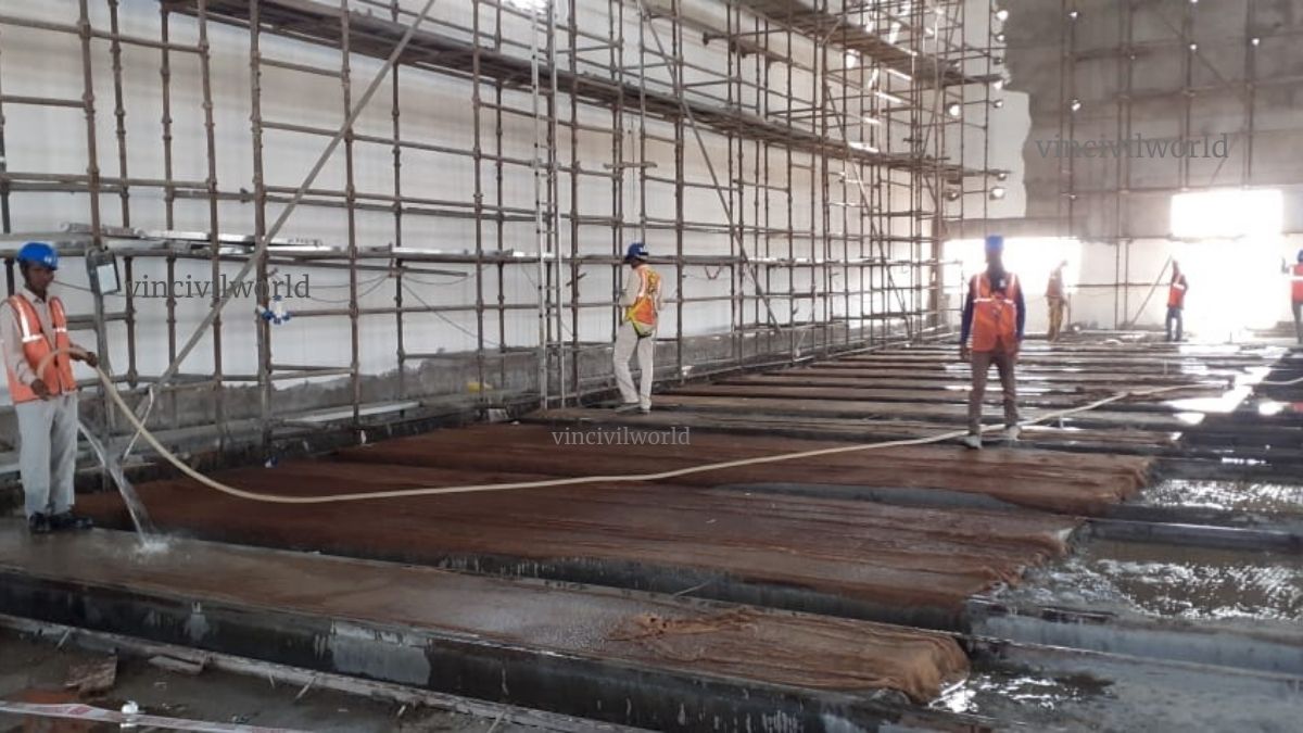
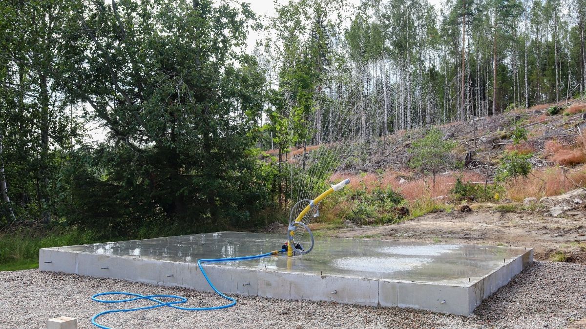
Controlling the Heat of Hydration on site involves lowering concrete temperature and slowing early reactions. Cooling techniques like chilled water, ice, or cooled aggregates reduce initial heat. Proper material selection, including low-heat cement and mineral admixtures, also helps. Optimized mix design strategies lower cement content. Adjusting construction timing to cooler hours and applying effective curing practices further minimise temperature rise and thermal cracking.
Key Takeaways
- The Heat of hydration of cement significantly affects concrete temperature, strength, and stability through the Cement hydration process.
- Cement undergoes five hydration stages, each influencing heat release and strength development in concrete.
- Field tests provide quick assessments of cement quality, while laboratory tests offer detailed evaluations of its properties.
- Controlling the heat of hydration involves cooling techniques, proper material selection, and optimised mix design strategies.
- The heat of hydration test is crucial for assessing cement’s performance and ensuring long-lasting, reliable structures.
Conclusion
Understanding the Heat of Hydration of Cement is essential for ensuring concrete quality, durability, and temperature control in construction. By analysing the Cement Hydration Process and the key Hydration Stages of Cement, engineers can accurately predict heat generation and early-age behaviour. This knowledge also helps identify the major Factors Affecting Heat of Hydration, enabling better decisions in material selection, mix design, and site practices. In mass concrete works, choosing suitable Low Heat Cement Applications prevents thermal cracking and enhances long-term performance. Ultimately, proper evaluation of hydration heat supports safer, stronger, and more reliable structures, making it a critical aspect of modern concrete engineering and quality control.