Heard about infrared thermography? We are going to deal with the topic in today’s blog.
I will walk you through the principle behind the technology, the classification based on its working, applications and the advantages and disadvantages.
What is Infrared thermography?
Infrared thermography uses thermographic cameras to detect radiation in the long-infrared range of the electromagnetic spectrum and generate images of that radiation, called thermograms.
The figure below shows the procedure of IRT.
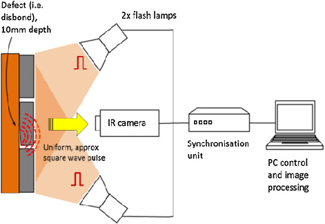
Source: Vollmer et al. (2010)
The principle behind infrared thermography is that the heat flow through the body is affected by the presence of internal anomalies. The main heat transfer mechanisms are conduction and radiation.
Now, let’s peep into the classification of infrared thermography.
Classification of infrared thermography
There are two types of classification based on different parameters.
1. Based source Of heating
- Passive Thermography- Passive thermography explicitly tests the surface temperature for measurement, as the interest area would have irregular hot-spot as compared with the surroundings
- Active Thermography- In active thermography, to detect inhomogeneities and cavities, heat is directed into a test piece. When a test object is heated or cooled, surface temperature variations are caused by local differences in the thermal conductivity and heat power of the test sample.
2. Based on method of heating
- Pulse Thermography- Infrared pulse thermography is a non-contact, non-intrusive NDE process commonly used for aircraft structure inspection. To unleash a thermal wave into the material for the detection of defects within the material, the technique employs a burst of high-intensity thermal excitation.
- Lock-in Thermography- Lock-in thermography is a method that uses a laboratory power supply and reed relays to automatically and repeatedly power a device at regular intervals while the device’s temperature response is integrated and measured over time.
In the next section, I will show you the advantages and disadvantages of infrared thermography.
Advantages of infrared thermography
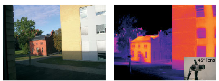
[Source: Vollmer et al. (2010)]
The main advantages of IRT are as follows.
- Early detection of defects
- No hazard
- Quick
- No time constraints
Disadvantages
The disadvantages of IRT are,
- High Equipment Cost
- Dependency on the environment conditions
- Dependency on the surface conditions
- Difficult to measure the depth of a flow
That’s it about the pros and cons. Let’s move on to the last section that talks about the interesting applications of infrared thermography in civil engineering.
Applications of infrared thermography
1. Bridge deck assessment
Bridge deck deterioration is an issue to be addressed with seriousness. Delamination and disintegration of concrete lead to this. Inadequacy of Traditional methods like sounding, chloride, corrosion potential gives way to IRT to be considered as the better alternative.
2. Testing for fibre reinforced plastic wrapped columns
- Subsurface debonds form between the fabric and the underlying member
- This affects the strength and ductility of the member
- IRT in rehabilitation work and periodic monitoring
- External Heat source is used
- Detection of subsurface debonds
- Repair using resin or replacement
3. Thermal Measurement And Control Of HMA Pavement Construction
The figure below shows the continuous thermal measurement system.
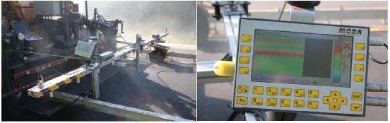
(a) Sensing Bar mounted to Paver (b) Display Screen
[Source: LeClair et al. (2015)]
- IRT can be used for real-time measurements of the surface temperature of the installed asphalt mat
- Map thermal contour on the surface of a material
- Identify temperature anomalies in cold areas
4. Energy Efficiency Assessment in Buildings
- It is used to identify and minimize the source of unnecessary heat flows.
- It makes use of the actual and expected 3D spatio-thermal models using EPAR
- The technique optimizes R-values using retrofit
- It helps to achieve optimal thermal comfort for occupants
- It also improves energy efficiency in buildings
5. Building Moisture Inspection
- In this application, IRT is utilized as a diagnostic tool to evaluate moisture
- It uses Moisture detector as a supporting device
- IRT identifies critical areas that were not detected visually
- Structural plans of the building should be checked
With that, we come to the end of this piece of information. Let’s wrap with the conclusion.
Conclusion
- Infrared thermography is a fast, clean and safe technology
- IRT is dependent on the sensor and the surrounding environment
- The defect can only be detected if it possesses enough thermal resistance
- IRT has wide applications in the realm of NDA as well as Civil engineering
So, how was the trip through infrared thermography for civil engineering? Was your time worth investing here with me?
If so, let me know your thoughts in the comment section.
Enjoy learning!