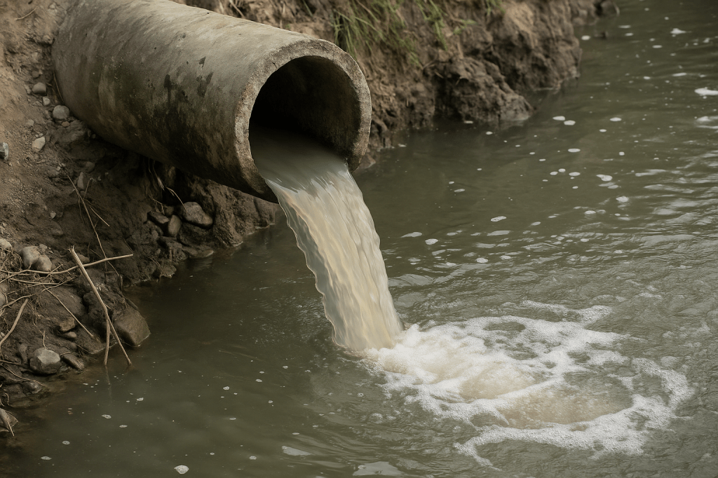
Primary wastewater treatment is the essential first step in preparing sewage for advanced purification systems. At this crucial stage, operators employ specific primary treatment methods to effectively remove large particles. This vital process prevents potential damage to valuable equipment and avoids obstructing the continuous flow of wastewater. The treatment process initially starts with screening, which extracts substantial debris from the incoming wastewater. Subsequently, grit removal follows, meticulously separating coarse waste, plastics, sand, and various stones. This diligent separation maintains smooth and efficient operation throughout all later treatment units.
After screening and grit removal, the wastewater progresses into settling tanks designed for purification. Within these tanks, the sedimentation process allows heavier solids to gracefully sink, consequently forming what is known as sludge. Simultaneously, lighter oils and greases accumulate on the surface, which are then carefully skimmed off.
By significantly reducing the overall solid load during these early stages, primary treatment demonstrably enhances the performance of all subsequent wastewater treatment stages. This method is notably simple, exceptionally effective, and absolutely crucial for safeguarding both valuable infrastructure and delicate natural water bodies.
Sewage is temporarily stored in a calm basin during primary treatment for wastewater. In this process, heavy materials sink. Oil, grease, and lighter solids float to the top. Wastewater reaching a treatment plant through pipes first undergoes primary treatment irrespective of its source.
In the previous blog, Wastewater Treatment- Stages and Process full details, I had given an overview of the wastewater treatment process. In this blog, we go on a trip with wastewater entering the primary treatment plant. Let’s dive deep into primary treatment for wastewater and closely observe each of the processes.
- Primary wastewater treatment stages
- Screening – Primary Treatment for Wastewater
- Flow Equalisation – Primary treatment for waste water
- Flocculation
- Scum Removal
- Conclusion
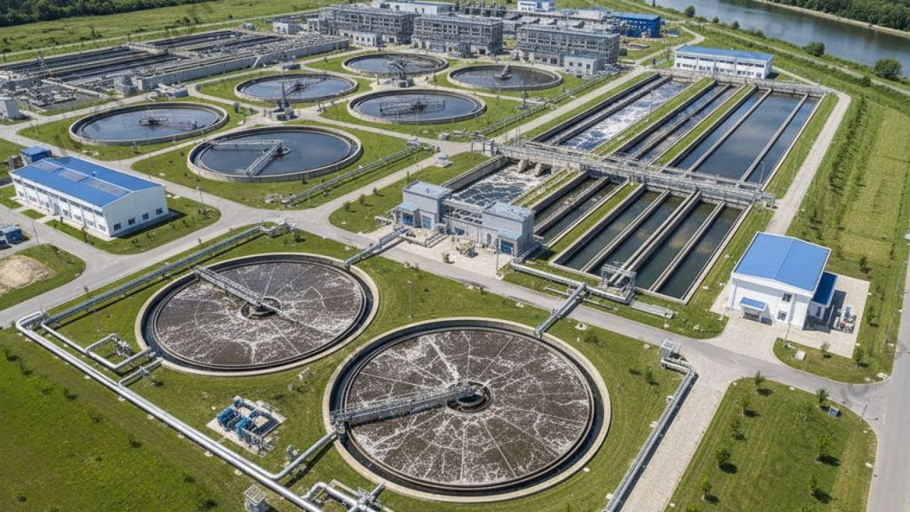
Primary wastewater treatment stages
Primary wastewater treatment process removes large and suspended solids using physical methods . This is to protect downstream units and improve overall treatment efficiency.
Main Stages
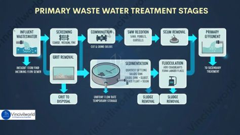
- Screening
- Grit removal
- Sedimentation (Primary clarification)
- Flocculation
- Sludge removal and handling
- Scum removal
Let us dive deep into each of the primary waste water treatment stages .
Screening – Primary Treatment for Wastewater
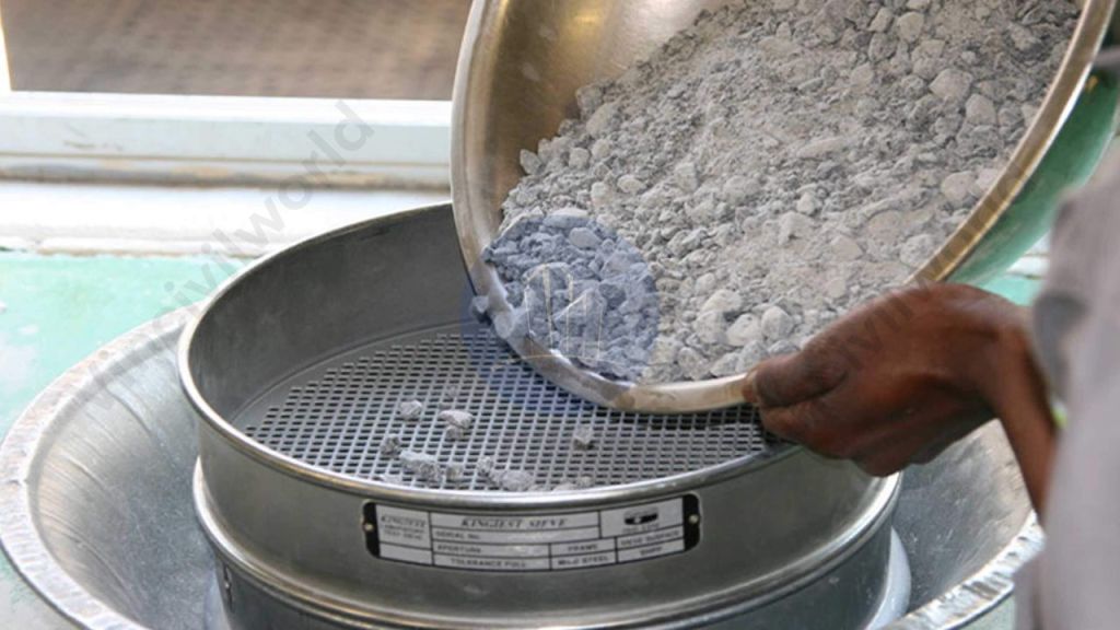
The first step in the primary wastewater treatment process is screening. This stage plays a major role in removing large solids before advanced treatment begins. In primary treatment for wastewater, the screening system blocks stones, rocks, and plastics. It even prevents dead animals from entering the treatment plant. These materials can damage pumps and obstruct the flow in pipelines. Therefore, eliminating solid waste at the initial stage makes all later wastewater treatment stages more efficient.
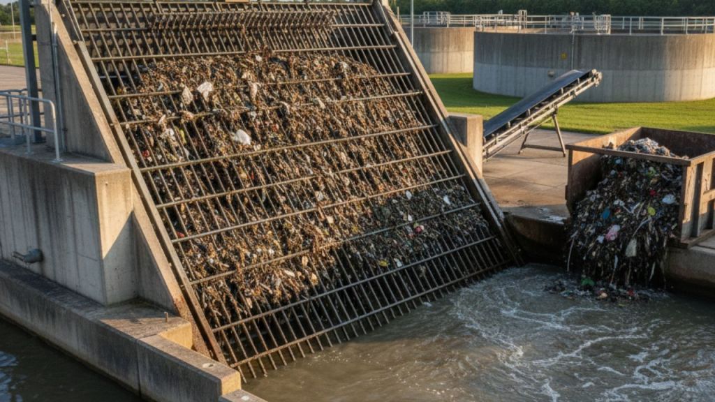
Screens and settling units remove most floating and large materials from the wastewater. The flow passes through screening and grit removal wastewater equipment such as bar screens. These screens consist of parallel metal bars, wires, or gratings placed at a 30°–60° angle to the flow. Based on the cleaning system, screens can be manually cleaned or mechanically cleaned. In manually cleaned racks, the opening size ranges from 25–50 mm. For mechanically cleaned screens, the opening size ranges from 5–40 mm.
Based on the size of the screen opening, we have 3 types of screens as follows:
- Coarse screens (≥ 50 mm)
- Medium screens (25-50 mm)
- Fine screens (10-25 mm).
Normally, domestic wastewater treatment uses medium screens. The channel approach velocities fall in the range of 0.3 to 0.6 m/s for manually cleaned racks and from 0.6 to 1.0 m/s for mechanically cleaned racks.
The wastewater moves to comminutors after screening.
Comminutors
Comminutors reduce bigger suspended particles to smaller sizes by cutting and grinding action. Large plants frequently employ comminutors. It consists of a fixed screen that has either a rotating or oscillating cutter. Alternatively, there is a curved screen with a rotating or oscillating cutter. They are of considerable importance in treatment plants located in cold areas since they eliminate the trapping of waste on freezing screens.
Next, we are going to see grit chambers and their functions.
Grit Chambers
Aerated grit chambers in primary wastewater treatment remove sand, gravel, and heavy particles using controlled aeration. This process protects pumps and improve the treatment efficiency.
- The wastewater after screening enters a grit chamber to settle the grit particles like sand, pebbles etc.
- Grit chambers are long and narrow tanks. They reduce the flow of water. This allows particles like sand, stones, and eggshells to settle out.
- They are highly relevant in places with combined sewer systems. These systems carry a significant amount of silt, sand, and gravel washed off roadways or land during a storm.
- They protect pumps and pipelines from abrasion and prevents the deposition of grit in pipes and channels.
Types of Grit chambers
Types of grit chambers in primary wastewater treatment help remove heavy particles and protect downstream equipment efficiently.
- There are two common types of grit chambers – Horizontal flow and Aerated.
- Horizontal Flow Grit chambers permit a velocity of about 0.3 m/s to settle the grit material while allowing the organic impurities to flow through the chamber.
- The aerated grit chamber constitutes a spiral flow aeration tank. Wastewater takes a spiral path through the aeration tank. This spiralling action throws away the grit particles into a hopper located underneath.
- Scrappers remove the grit for disposal.
Flow Equalisation – Primary treatment for waste water
- Under uniform flow rates, clarifiers and mechanised secondary treatment are more efficient.
- Equalization basins store diurnal or wet-weather flow peaks temporarily and make the water flow rate uniform.
- Basins serve as a temporary holding area for the incoming wastewater during temporary plant shut down and maintenance.
- It acts as a means of diluting and distributing hazardous or high-strength waste into batches.
- Flow equalisation basins require variable discharge control which features bypass and cleaning options as well.
- Cleaning is easier if the basin is downstream of screening and grit removal.
Also read : What are Water Pollutants? – Definition, Sources and Types
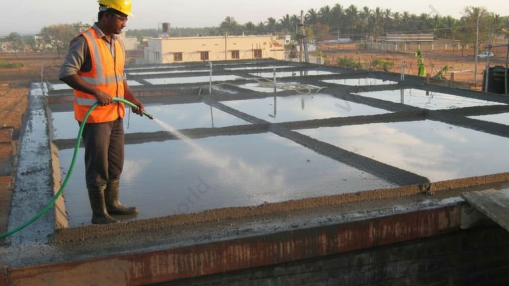
Sedimentation – Primary treatment for wastewater
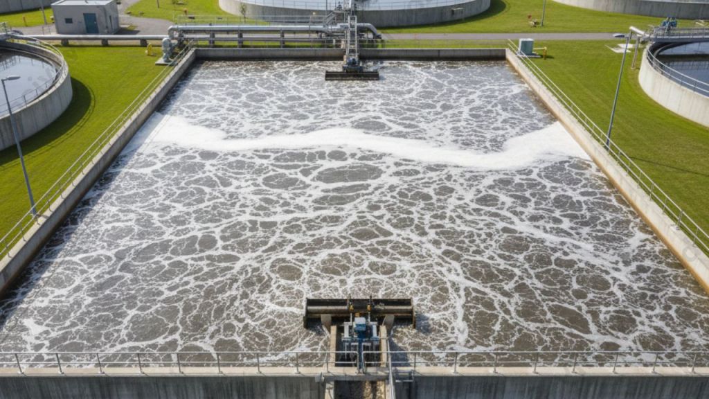
The wastewater, then moves to sedimentation ponds, settling tanks, or clarifiers after the removal of settled grit. The sedimentation process removes the settleable solids by gravitational settling under quiescent conditions.
On proper adjustment of water flow in the sedimentation tank, the suspended particles begin to fall to the bottom and form a solid mass. Raw primary biosolids, also known as sludge, is the solid mass formed out of the particles. This sludge is removed by vacuum suction or raking it to a discharge point.
Types of Primary Sedimentation Tanks
- Rectangular Horizontal Flow Tank
- Circular Radial Flow Tank
- Up Flow Tanks
Rectangular Horizontal Flow Tank
- Feed enters at one end along the width of the horizontal tank.
- They can be economically built side-by-side with common walls.
- Length ranges from15 to 100m and width ranges from 3 to 24m (length/ width ratio 3:1 to 5:1).
- In rectangular tanks, the flow occurs in a horizontal, lengthwise direction.
- Rectangular tanks, sometimes use baffle walls to prevent short-circuiting.
- Rectangular sedimentation tanks provide reduced maintenance expenses.
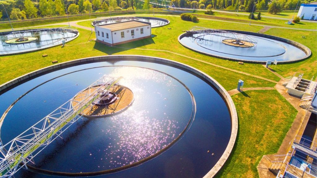
Circular Radial Flow Tank
- In circular radial flow tanks, influent is fed through a central pipe of the tank and radial flow happens.
- They have diameters ranging from 3 to 60 metres (side water depth range from 3 to 5m).
- Mechanical sludge scrapers gather the sludge, and a sludge pipe transports it to the bottom.
- Circular tanks are more expensive than rectangular tanks, but they have a higher clarification efficiency.
Up Flow Tanks
- Up Flow tanks find application in small treatment plants.
- Feed enters through openings along the bottom side of the tank and the effluent after clarification collects at the top.
- The flow takes place in a vertical direction.
- A sludge blanket in the lower part of the tank acts as a filter for small particles.
The next stage is flocculation which removes the remaining suspended solids.
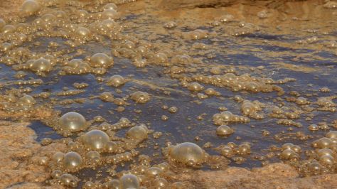
Flocculation
Flocculation is a water treatment process to remove small suspended solids which don’t settle in the sedimentation tank. In this process solids form larger clusters, or flocs on the addition of a flocculent like aluminium sulphate.
The coagulant molecules have a positive charge. Hence, they can neutralize the negatively charged solid particles that are suspended in the water. Neutralization of the particles initiates the flocculation process. The individual suspended particles come together to join and form a larger mass called a floc.
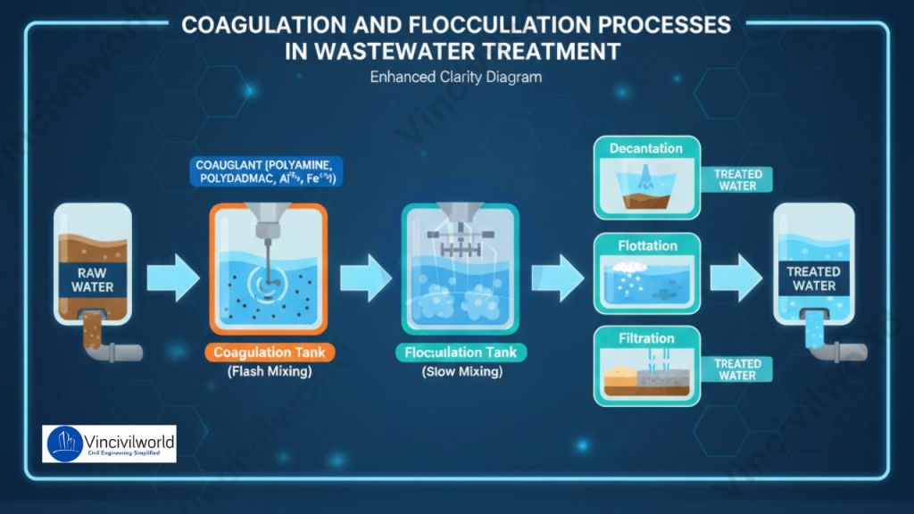
At the onset of flocculation, we add a chemical polymer. It acts as a bridge between micro and macro flocculants, increasing the mass of particles aggregating together. It also bonds the accumulated material together, preventing it from dissolving even when the water is stirred slightly. After the flocculation, the solid masses are removed either through settling or through the use of filters.
Sludge Removal
In the sedimentation tanks, sludge (the organic component of the sewage) settles out of the wastewater. Mechanical scrapers in the tank’s base continuously move accumulated sludge to a hopper, where it is pumped to sludge treatment facilities. The thickening step removes some of the water before processing the sludge in digesters.
Also read : Activated Sludge Process – Stages and Process Control
Scum Removal
Lighter materials rise to the surface as sludge settles to the bottom of the sedimentation tanks. The constituents of ‘scum’ are grease, oils, plastics, and soap. Scum is skimmed off the surface of the wastewater by slow-moving rakes. Scum is thickened before being poured into the digesters with the sludge.
Primary treatment removes about 60% of the total suspended solids and nearly 35% of BOD. It doesn’t remove the dissolved impurities. The waste must undergo secondary treatment in order to be completely free of toxic substances.
Also read : Biochemical Oxygen Demand
That’s it about primary treatment for wastewater. But, our trip doesn’t end here. Next, we move on to the secondary wastewater treatment plant – Secondary Treatment for Wastewater – Methods and Process. So, how was the trip? Let us know in the comment
Key Takeaways
- Primary Treatment for Wastewater is the first crucial step in treating sewage, removing large particles to protect equipment.
- It involves screening, where coarse waste is separated, followed by grit removal and sedimentation processes.
- Sedimentation allows heavier solids to settle, forming sludge, while oils and greases float to be skimmed off.
- The process removes about 60% of total suspended solids and 35% of biochemical oxygen demand, but not dissolved impurities.
- Following primary treatment, wastewater must undergo secondary treatment for complete purification.
Conclusion
Primary treatment for wastewater plays an essential role in protecting both treatment facilities and the environment. It removes large solids, sand, grit, oil, and floating debris before advanced purification begins. Processes like screening, grit removal, sedimentation, and flocculation work together to reduce the pollutant load effectively. By eliminating harmful materials early, primary treatment improves the efficiency and lifespan of pumps, pipelines, and biological treatment units. It also ensures that downstream processes receive cleaner wastewater, leading to better final effluent quality. Although simple and cost-effective, primary treatment remains the foundation of a reliable wastewater treatment system. Therefore, investing in and maintaining strong primary treatment operations is crucial for sustainable water management and public health protection.