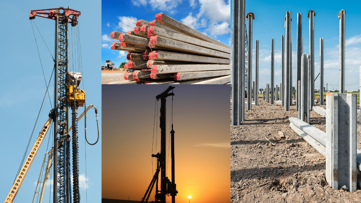
Driven piles support structures and transmit loads to underlying soil or rock, as they are a type of deep foundation used for this purpose. Contractors use driven piles, made of steel, concrete, or wood, to support structures and transmit loads to underlying soil or rock. They also call them displacement piles. The installation of driven piles involves driving them into the ground using impact hammers or vibratory drives until they reach a layer of rock or soil that can support the required loads.
If the soil is exceptionally dense, they may need to pre-drill to ensure the pile reaches the design depth. Construction projects commonly employ driven pile to provide stability and strength to the structure. Driven piles offer a cost-effective deep foundation solution and are commonly used to support buildings, tanks, towers, walls, and bridges.
- Why driven piles?
- Types of driven piles
- Quality Control for Driven Piles
- Advantages of driven piles
- Disadvantages of driven piles
Why driven piles?
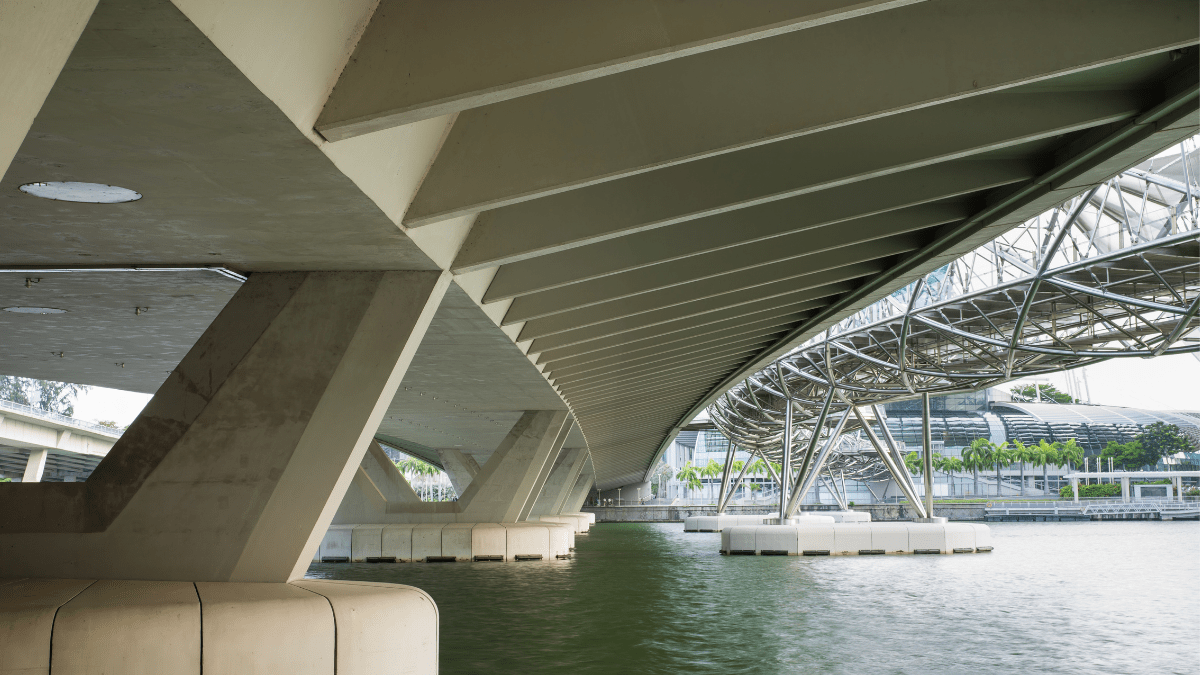
Contractors often use driven piles, which are the most cost-effective deep foundation solution, to support buildings, tanks, towers, walls, and bridges. They are also suitable for embankments, retaining walls, bulkheads, anchorage structures, and cofferdams. Driven piles possess a high load-bearing capacity, durable, and contractors can install them quickly and effectively in various soil conditions. Engineers frequently use them in places with inadequate soil, where conventional shallow foundations would not be strong enough to sustain buildings.
In addition, contractors can install driven piles to support compression, tension, or lateral loads, with specifications determined by the structure’s needs, budget, and soil conditions, making them very versatile.
Related posts from vincivilworld

Types of driven piles
Driven piles are broadly classified as follows
- Steel Driven pile
- Precast Concrete Driven pile
- Timber pile
- Composite driven pile
Steel Driven pile
Steel-driven piles support major structures such as buildings, bridges, roads, and industrial facilities in construction. Construction workers push them into the earth using specialized tools like hydraulic hammers or pile drivers until they reach a predetermined depth or a firm layer of rock or soil. Steel-driven piles are steel beams with broad flanges on both ends.
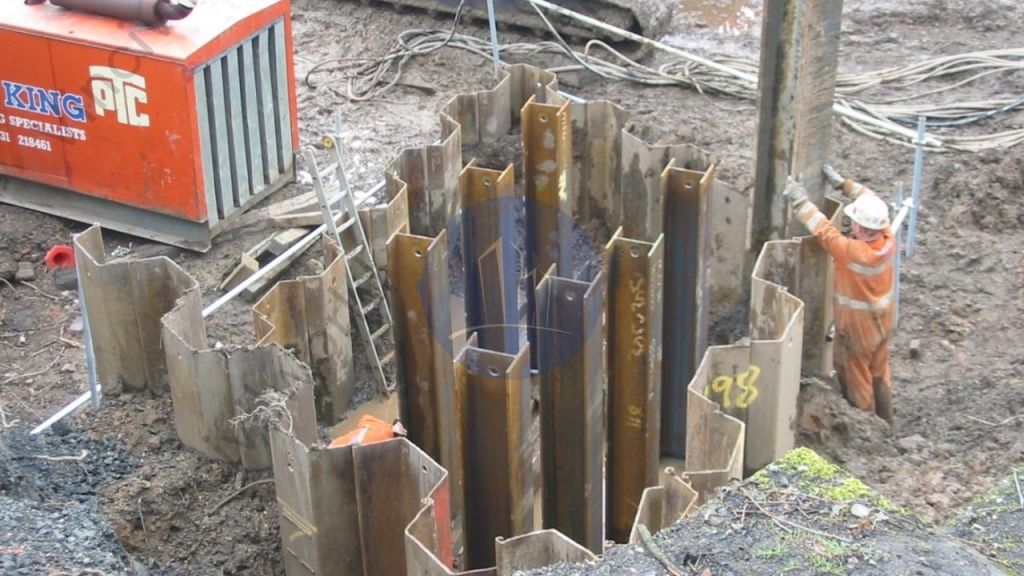
Steel-driven piles are typically made of high-strength steel with a round or square cross-section. They come in various lengths and widths and can be installed vertically or at an angle to meet foundation design requirements. An impact hammer is used to press the pile into the soil by delivering a forceful blow. For shorter depths, steel screw piles are supported by a cast iron helix and powered by rotary motors.
Because of their durability, strength, and capacity to support enormous loads, the steel-driven pile is a common choice for deep foundations. Steel-driven piles are a cost-effective and quick solution for many construction projects. However, their applicability will depend on factors such as soil characteristics, anticipated loads, and local construction building codes and regulations.
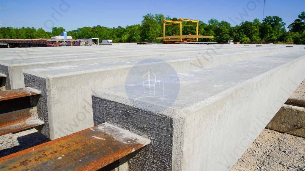
Pre-cast concrete Driven Piles
Precast concrete pile manufacturers deploy these piles in construction to support structures built on weak or compressible soils. They prefabricate these piles in a factory or casting yard before transporting them to the construction site. Based on the project’s unique needs, they can construct precast concrete piles in a vast range of dimensions, forms, and configurations. High-strength concrete, reinforced with steel rebar, is used to make these piles. They often use a vibratory hammer or hydraulic hammer to drive the piles into the earth until they reach the required depth or a solid layer of soil or rock.

Piles come in a variety of shapes, such as square, octagonal, cylindrical, or sheet. Percussion-driven piles are used in situations where bored piles would be ineffective due to running water or excessively loose soils. They have a load range of 300-1,200 kN and a maximum reach of 30 m. Precast concrete piles are constructed with great accuracy and quality control in a controlled environment, resulting in a consistent and uniform product that satisfies design requirements. They are durable and can withstand adverse weather conditions such as seawater or chemical exposure. Precast concrete piles can also be installed quickly and effectively, saving time.
- Precast concrete piles are quick to install.
- They can be used in various soil conditions.
- Using precast concrete piles saves time and money in construction.
- Precast concrete piles are durable and reliable.
- They have high-quality control standards.
- Precast concrete piles are a popular choice for deep foundation construction.
Timber pile
Timber-driven piles are used in construction to create a stable foundation for structures in weak or compressible soils. Contractors use hammers or pile drivers to create cylindrical or square wood piles from premium softwood species. This type of pile is particularly effective in areas with high water tables where other types of piles may not work as well. Timber-driven piles provide a stable foundation for structures in weak or compressible soils. This is achieved by hammering wooden piles into the ground, which compresses the wood and displaces the surrounding soil. The resulting tight fit helps to support the weight of the structure. Timber-driven piles have the advantages of being inexpensive and simple to install. Nonetheless, they may be susceptible to rot and pest infestation.

Composite driven pile
Engineers commonly use composite piles made of a combination of two or more materials, such as concrete, steel, or timber, when soil conditions require a combination of strength and flexibility. An example of a composite pile is a concrete pile with a steel section, as shown in the figure.
Contractors use composite-driven piles consisting of a steel tube filled with concrete and reinforced with steel rebar because they can withstand heavy loads. They use in various construction projects, such as bridges, high-rise buildings, and marine structures. The steel tube provides structural support and protects the concrete from damage during installation, while the concrete and rebar provide additional strength and stability. Contractors can install composite piles using hydraulic hammers or vibratory drivers to reach depths of up to 60 meters. Due to their durability and corrosion resistance, composite piles are ideal for use in harsh environments.
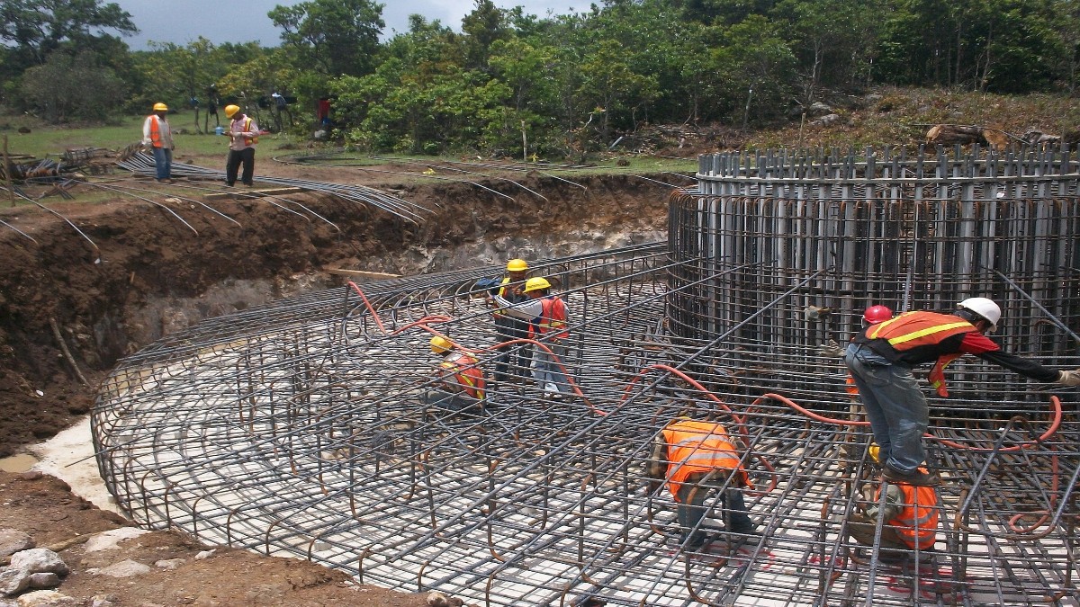
Quality Control for Driven Piles
The construction of driven piles requires high-quality materials and adherence to standards such as BS 8004:2015 and EC standards. It’s crucial to maintain the pile’s shape and avoid damage during installation and inspect them beforehand for quality assurance. The maximum load a pile can carry depends on soil or rock strata properties, pile dimensions and material, and installation method. Engineers perform load testing on representative samples to determine capacity and use monitoring instruments like inclinometers and settlement gauges to ensure the pile’s sufficient support. Effective quality control and testing are crucial for the safe and reliable performance of driven piles in construction projects.

During installation, it is crucial to maintain the shape of driven piles and ensure they are not damaged by the installation of subsequent piles.
Quality control of driven piles is an important aspect of ensuring the stability, safety, and longevity of structures that rely on them for support. Here are some of the common quality control measures used for the driven piles.
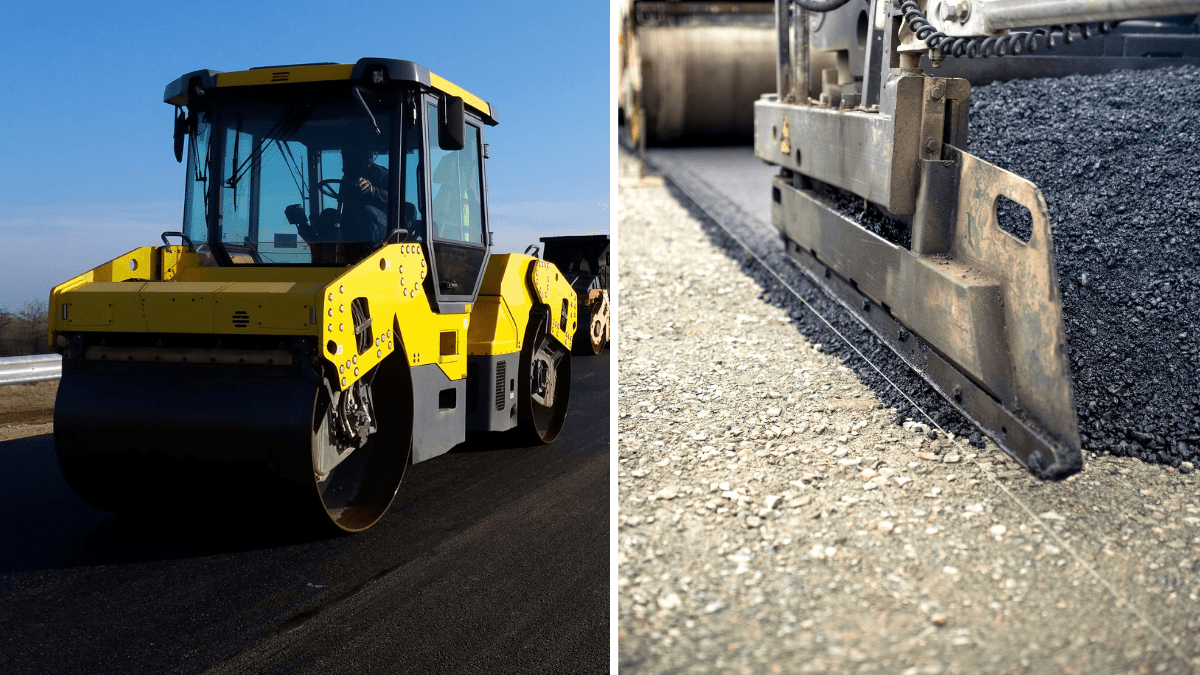
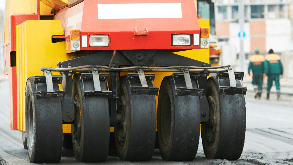
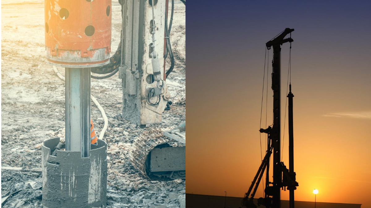
Pile driving equipment for driven piles
To make sure that piles are installed correctly, trained personnel are required to maintain, calibrate, and operate pile driving equipment properly. Regular inspections are necessary to detect any damage or wear in the equipment, and repairs or replacements must be made promptly.
Pile inspection and testing
Inspect the piles for defects or damage before driving them into the ground. To ensure that the piles have been installed correctly and meet the specified requirements, non-destructive testing methods such as sonic testing or integrity testing should be used to test the piles after installation.
Pile load testing for driven pile

One can conduct load testing of a sample of piles to ensure that they can support the required loads. This involves applying a controlled load to the pile and measuring the resulting deformation, which one can compare to the design specifications to ensure that the piles are safe and reliable.
Pile driving records
One should keep detailed records of the pile driving process, including the number of blows or vibrations required to drive the pile to the required depth, the penetration rate, and any other relevant information. These records are essential to monitor the quality of the installation and identify any issues that may arise during the construction process.
Regular inspections and testing are essential to identifying any issues early in the construction process and enabling prompt corrective action.
Advantages of driven piles
The main advantages are
- Piles can be pre-fabricated off-site which allows for efficient installation once on-site.
High Capacity
Piles are driven deep into soil or rock. This provides high load-bearing capacity. It’s suitable for supporting heavy structures like buildings, bridges, and marine structures. The process increases the effective length of the pile, resulting in high capacity.
Ease of Installation of driven piles
Compared to other pile types like drilled shafts, the installation of a driven pile is quick and efficient. The installation process involves driving the piles into the ground using an impact hammer or a vibratory driver. This requires minimal excavation and soil removal.
Cost-effective
Other types of foundation systems can often be more expensive than driven piles, particularly when the soil conditions are favourable. The cost-effectiveness of driven piles is due to their relatively simple installation process and the availability of pre-manufactured piles, which can reduce the time and cost required for pile installation.
Minimal disturbance
The installation process of driven piles minimizes the disturbance to the surrounding area, making them suitable for use in urban or environmentally sensitive areas. The piles are driven into the ground, which reduces the amount of soil disturbance and the need for excavation.
Versatility
Driven piles are suitable for a variety of soil conditions, including soft soils, hard soils, and rock layers. They can also be made of different materials such as steel, concrete, and timber, providing a wide range of design options.
- When driven into the ground, piles displace and compact the soil, resulting in increased bearing capacity. In contrast, other types of deep foundations may require soil removal, which can cause subsidence and structural problems.
- Installation usually produces little spoil for removal and disposal.
Overall, driven piles offer several advantages in terms of high capacity, speed of installation, cost-effectiveness, minimal disturbance, and versatility, making them a popular choice for foundation systems in many construction projects.
However, the use of driven piles also has some disadvantages, including their relatively high cost compared to shallow foundations, the noise and vibration associated with their installation, and the potential for damage to nearby structures or utilities. Therefore, the selection of driven piles as a foundation type depends on a variety of factors, including soil conditions, load requirements, and site-specific constraints.
Disadvantages of driven piles
In the design and construction process, it is important to consider the disadvantages of driven piles, despite their many advantages. Some of the main disadvantages of driven piles are:
Noise and vibration
The installation of driven piles can generate high levels of noise and vibration. This can be a concern for nearby residents and sensitive structures. Pile driving can cause damage to nearby structures, particularly those with shallow foundations.
Limited depth
Other foundation types may be necessary if the capacity or depth required cannot be achieved with driven piles. This is because of the limitations imposed by soil or rock conditions and the driving equipment’s capacity.
Difficulty in driving through hard soil or rock
Driving piles in hard soil or rock layers can be difficult and time-consuming, which can lead to higher installation costs. Overcoming the hardness of the soil or rock may also require the use of specialized driving equipment or techniques.
Quality Control
The installation of a driven pile requires critical quality control. Poor installation can cause issues such as pile damage, pile movement, or insufficient load capacity. To ensure that the piles are installed correctly and meet the required standards, regular inspection, and testing are required. Moreover, monitoring is necessary during pile installation.
Limited environment suitability
Driven piles may have limited suitability in environmentally sensitive areas. This includes wetlands or areas with a high water table. This is due to the potential soil disturbance caused by the driving process. Moreover, the use of chemicals for the preservation or treatment of piles can have negative impacts on the environment. It is important to consider these factors and explore alternative foundation options in such areas.