All posts by Vinod Gopinath

Types of Culverts – Culverts meaning and Culvert types Explained

The types of culverts to be deployed depends on the site conditions and the purpose of the culvert. Culverts are tunnel structures constructed beneath rail tracks or roadways to facilitate cross drainage or to convey electrical cables from one side to the other. It is completely encircled by ground or soil. Pipe, box, and arch culverts are the most common types of culverts deployed under roadways and railroads. They should run parallel to the ground. The culverts protect the road from erosive forces and other water-related concerns. Hydraulic, water surface elevation, roadway height, and other parameters influence culvert designs. Moreover, culverts are used to regulate the flow of water.

This article is about the meaning of culverts, the types of culverts, and their advantages.

What are culverts?

A culvert is a permanent or temporary structure that enables water to flow beneath a road or railroad. It is best suited for locations where roads or railroads need to be built near existing rivers or canals without interfering with water movement. Generally, the length of the culvert should be 6 meters or less. As a result, they are quite large. Concrete, aluminium, and steel are among the materials used in the culvert’s construction. However, the material choice is influenced by criteria such as hydraulic efficiency, strength, cost, and installation technique. Concrete is preferred for culverts due to its strength and durability. Moreover, they are also more resistant to highly corrosive conditions.

Materials for culvert construction

Culverts are similar to pipes but much larger in size. They are manufactured from a variety of materials, like
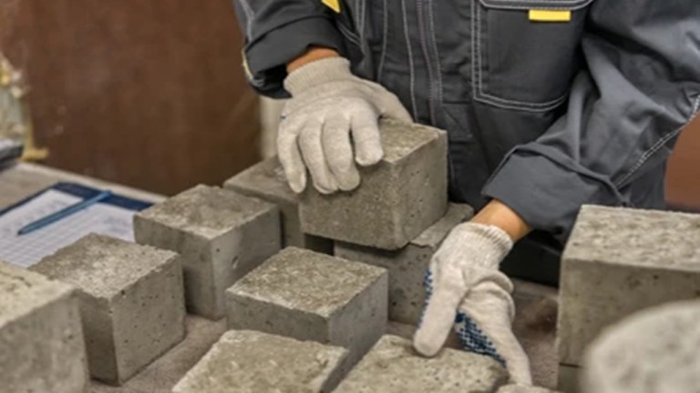
  • Concrete
  • Steel
  • Plastic
  • Aluminium
  • high-density polyethene

Culverts made of concrete are typically preferred. Concrete culverts can either be reinforced or unreinforced. Culverts that are built on-site are known as cast-in-situ culverts. Precast culverts, which can be manufactured elsewhere, transported, and assembled on-site, are another possibility.

The aforementioned materials can be combined to create composite culvert types.

Different Types of Culverts

There are numerous varieties of culverts. The amount of water, the elevation of the road, the site’s condition, the area of water release, etc. are all taken into consideration while choosing the size and type of the culvert.

Most used culvert types are as follows

  • Pipe Culvert
  • Pipe Arc Culvert
  • Box Culvert
  • Arch Culvert
  • Bridge Culvert/Slab culvert
  • Metal Box Culvert

Pipe culverts

A culvert is a covered hydraulic structure that conveys fluid. Pipe culverts are constructed by inserting a pipe into an excavated trench to convey water away. It is the most frequently used drainage system. Pipe-type culverts are fairly prevalent due to their economical cost and ease of installation. In terms of hydraulic performance, the round section is the best geometrical section. Pipe culverts, on the other hand, come in a variety of shapes, including elliptical, pipe arch, and others. In general, the shape of the culvert is governed by site constraints and conditions. The culverts could be single or multiple. For comparatively small discharges, circular precast concrete pipes and ductile iron pipes are commonly used.

pipe culverts
pipe culverts

Pipe Arch Culverts

Arch culverts are semi-circular in shape. They are appropriate for larger waterway openings with steady water flows wherein fish can benefit from a greater hydraulic advantage. however, need to provide a steady water flow. Fish or sewage in the drainage is easily moved to the outflow due to the arch shape, as there is no stocking at the intake or bottom of the channel. Depending on the need, this type of culvert can also be provided in multiple numbers. Additionally, they offer little clearance and are undoubtedly quite artistic. Pipe arches have a hydraulic advantage at low flows and are particularly beneficial for locations with limited headroom. The main advantages of pipe arch culverts are their light weight and ease of installation.

pipe arch culverts
pipe arch culvert (Photo credits: https://www.rinkerpipe.com/Products/ArchPipe.aspx

Box Culvert

Box culverts
Box culverts

These culverts are used for intakes and outtakes, holding tanks, steam tunnels, corridor linkages, road crossings, service tunnels, and utility trenches. They are one of the most useful structures in modern construction and are common components in road and highway construction. These box culverts allow water to flow beneath roads and highways without interfering with traffic flow and serve as alternate animal crossings. Box culverts are rectangular or square in design, and they must be sturdy to endure traffic loads and harsh weather conditions. Because of this box culverts are constructed using Reinforced cement concrete. The most difficult aspect of building a box culvert is that it must be installed in a dry area with a firm base.

When a significant amount of water is anticipated, the strength of the concrete floor allows for a shift in the water flow direction. Box culvert may also be of the precast type. Circular concrete pipes are replaced by precast concrete box culverts. They have higher strength, can easily withstand greater water flow than standard pipes, and can drain extremely huge amounts of water. Box culvert installation is simpler and more practical than other types of culverts.

Precast box culvert can be prepared in advance, and then installed in the locations required when the time comes.

Arch Culvert

An arch culvert is constructed of metal, stone masonry, concrete, RCC, and other materials. Arch culverts are similar to pipe arch culverts, except in this instance an artificial floor is constructed underneath the arch. The arch culvert demands the construction of a superstructure, that comprises one or two segmental arches. It is frequently used for narrow passages. Contrary to box culverts, installation can be completed quickly and without disrupting the flow of the water, therefore water diversion is not necessary. The natural integrity of the wash bed is preserved by this type of culvert.

arch culverts
arch culvert

Similar to masonry bridges, arch culverts are economical, fast, and easy to construct. They benefit from the design-build advantage and improved hydraulic effectiveness. The arch culvert is also made of steel but it is very extortionate. The arch culverts are not provided with the piers to the sides of the abutment

Slab culvert/Bridge Culvert

Bridge culvert
Bridge culvert

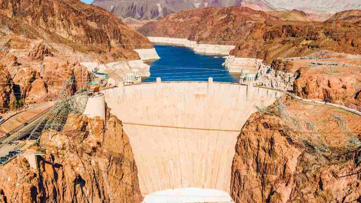
Bridge culverts are generally constructed on rivers and canals. They are also used as vehicle bridges. As a result, it is referred to as a multi-purpose culvert. Most foundations are built below the surface of the ground. A number of culverts are installed, and then a pavement surface is placed on top of them. Slab culverts and bridge culverts may have three sides or may just be flat slabs. Both sides of it are buried in the ground. These culverts, which are typically rectangular in shape, can take the place of box culverts if artificial flooring is not required. The typical span length is between 8′ and 48′. Being able to accommodate traffic on it, being the most expensive river crossing, being extremely sturdy, and got a very strong foundation.

The benefits of a bridge culvert are that it allows traffic to travel through it, it is the most expensive river crossing, it is very strong, and it has a very strong base. Because slab culverts don’t have bottom slabs, the normal flow of water is maintained, and the natural bottom substrate remains undisturbed. The slab culvert is safe for high-velocity vehicles because it has no sharp corners.

Metal Culvert

Metal culverts
Metal culvert

The metal box culvert is an economical alternative to bridges. These bridges are made of conventional structural plates or deep-corrugated structural plates. They are the ideal bridge replacement since they keep the same road grade level. Construction of a metal box culvert requires little time and is relatively easy to install. They are more durable and have a longer service life.

For projects that need larger diameter pipe than what Metal Culverts can manufacture (more than 144′′ diameters), Structural Plate and Aluminum box Culverts are ideal. This solution enables quick and simple installation at a fraction of the price and time that replacing a steel bridge would cost. Aluminium box culverts and structural plates are available for use in various applications, such as small bridge replacements, pedestrian passages, livestock underpasses, and stream enclosures. Structural Plate’s shape also helps maintain the natural environment in which pipes are installed. The arch shape allows wildlife to pass through without difficulty and can also leave natural stream beds intact.

A Comprehensive Guide To Construction Drawings For Your Building

The Construction drawings for a house are the most important document in home-building. It contains instructions on how to construct your new house or add-on, which contractors to hire, and how they should do their job.

A blueprint is an overview of the entire construction project photographed from above. It means that all of the construction drawings for your building will be contained within a single blueprint sheet, making it easy to follow along with what’s happening during various stages of construction. A blueprint sheet will have a lot of information.

Each scale drawing has a title, starting with the plan, the number, and name of the architect, scale measurements, and legal description of the property. You will also see different scale drawings.

Different Types Of Assembly Drawings

There are many types of assembly drawings. They include foundation, tanking and foundation cut-always, crawl space and slab information, parapet wall, and roof details. Foundation drawings are required for new construction, additions, and modifications to existing structures. It shows all the walls, floor supports, and footings used to support the house’s floors, structures, and external components.

1. Standard Assembly Drawings – 

These drawings are a set of drawings that show how to put the parts together. It establishes a basis for construction and design. The main elements are framing, sheets, lumber, blocking, and trim/molding materials.

Structural fabrication and erection

2. Outline Assembly Drawings –

A preliminary set of drawings establishes the general appearance of the work.

3. Detail Assembly Drawings – 

It provides more detail on construction details such as existing and proposed walls, ceilings, and other finishes.

4. Assembly Working Drawings – 

The drawings show the construction process and include foundation details of the framing, floors, cabinets, and stairs.

5. Tabular Drawings – 

It contains all the information needed to construct the project. They are usually kept in a text file or spreadsheet and give you information on the actual sizes, quantities, and room locations.

6. Diagram Drawings – 

Diagram drawings are simple drawings of a floor plan and elevation drawings that show how any given elements work to create the project’s design.

Also read: Areas of building | Built-up area | Carpet area | Super built-up area

Why Are Assembly Drawings Necessary?

All structural elements of the building must be drawn in detail, anticipating all expected loads on the structure. These details must also include all internal and external spaces within the new building, anticipate potential problems, and propose solutions.

Structural drawings are the blueprints of the construction sheets: they show all structure elements, including beams and columns, walls, and flooring. It is a series of symbols and lines that illustrate any load-bearing or non-load-bearing walls. Sustainable cities and constructions of the future require high-quality structural drawings.

What Are The Major Inclusions Of Assembly Drawings?

Building plans include a profile view of your house, including the side elevations or front and rear views. In addition, the plan sets out the orientation of your house, inside to outside. When reading a structural drawing, you need to understand that there are many different kinds of assemblies. However, there are three basic types of structurally significant assemblies: frame, floor, and roof.

  1. A-frame assembly comprises a top plate, bottom plate, and posts. The basic elements of an assembly are the post. These are angled beams that are attached to foundation walls, floors, or exterior walls.
  2. The landfills and roof beams are considered as frame assemblies. They include facets such as posts, beams, headers, and joists or wooden floorboards. The next assembly is a floor assembly. It is a structural system that supports the weight of all upper floors and roofs. 
  3. The roof assembly is the third major structural assembly. It consists of a top and bottom chord, common rafters, collar ties, or trusses.
Building construction drawing

The Importance Of Construction drawing In Designing A Building

  1. Scope of construction – 

Construction drawings are all about explaining and showing the finished product. The job is to document and view the construction process. That’s why structural engineers design the building, show their drawings, and then give their clients a set of construction drawings.

  1. Importance of construction drawing

The drawing is about the design and the assembly of everything working together for a living space, so you need to be able to tell more than one story. It deserves a lot of attention.

  1. Staff size – 

It is a big job, and they usually work with several people who help them draw the design and then give the construction drawings to the client.

  1. Provides information – 

It involves many people who have to provide a lot of information. This information should be precise and clear, as it is about planning for the future.

  1. Safety –

 It plays an important role in the design and construction process to ensure the safe construction of the building.

How To Produce A Construction Drawing 

There are many ways to make construction drawings. Today’s most common ways workers use photo plotting, CAD (Computer Assisted Drawing), and hand drafting. CAD is an advanced technology, and using it is quite easy. India CAD works enable you to make construction drawings with ease. You can create as many construction drawings as possible and share them with your clients. Many construction companies use it to execute their projects and make best-selling construction drawings for their clients. With CAD, you can create various drawings, from simple to complex. You can design and add any number of view layers and color them in any way you like.

Classification of Surveying – A complete overview

Classification of Surveying is a fundamental topic in civil engineering. This is because almost every project begins with measuring and mapping the ground. Surveying determines the relative position of points on the earth. It also measures directions, distances, elevations, and areas. These measurements are used to prepare layouts at a chosen scale. In practice, surveyors apply different Types of Surveying and Land Surveying Methods through reconnaissance, measurement, marking and plan preparation. These Surveying Techniques in Civil Engineering demand high precision and good mathematical skills to analyse field data accurately. By understanding Methods of Surveying Classification, including the difference between Plane vs Geodetic Surveying, engineers can select the most suitable approach for each site and structure. In this article, we explore how surveying is classified and where each type is typically used.

  1. Classification of surveying
  2. Primary classification of surveying
    1. Plane surveying
    2. Geodetic surveying
  3. Classification of surveying based on field nature
    1. Land surveying
      1. Topographical surveying
      2. Cadastral surveying
      3. City surveying 
    2. Hydro-graphic surveying
    3. Astronomical surveying
  4. Classification of surveying based on purpose
    1. Engineering survey
    2. Military survey
    3. Mining surveying
    4. Geological survey
    5. Archaeological survey
  5. Classification of surveying based on instruments
    1. Chain surveying
    2. Theodolite surveying
    3. Traverse survey
    4. Triangulation survey
    5. Tacheometric survey
    6. Plane table survey
    7. Photogrammetric survey

Classification of surveying

Surveying is divided into different types to ensure accurate measurement methods are selected for specific project requirements and field conditions.

  • Primary classification of surveying
  • Classification of surveying based on field nature
  • Classification of surveying based on purpose
  • Based on Instruments classification of surveying

Also Read : Principle of surveying – First and second principle

The details of every classification basis is explained in detail in this article

Classification of surveying - Total Station
Classification of Surveying – Total Station

Primary classification of surveying

The primary classification is based on the earth’s surface. We know earth is an oblate spheroid. So while surveying we must consider the earth as either plane or as curved. Primarily we can divide surveying into two types and are as follows.

Plane surveying

For plane table surveying the earth’s surface is considered as a plane. Therefore we should neglect the corrections due to earth curvature. The line which connects these points is a straight line. The triangles made by joining these lines are Plane triangles. This type of surveying is useful for limited areas. ie less than 200 sq.m.

Geodetic surveying

In Geodetic surveying, the earth’s surface is considered as a curve. So the line which connects these points are curves and the triangles made joining these lines are Spherical triangles. Geodetic surveying is used for large areas of more than 200 sq.m.

Classification of surveying based on field nature

Land surveying

Land surveying is the art of establishing or re-establishing corners, lines, boundaries, and monuments of property or land. This is based upon recorded documents, historical evidence, and present standards of practice. It helps in preparation of topographical maps, planning, and estimation of project works, locating boundary lines, etc. Land surveying is classified into three types.

  • Topographical surveying
  • Cadastral Surveying
  • City surveying

Topographical surveying

The main application of a topographical survey is the drafting of maps. Topographical surveys include surveying natural and artificial features such as rivers, hills, roads, canals, etc. It consists of horizontal, vertical, and angular measurements. The scale range is 1: 25000 to 1: 1000000.

Cadastral surveying

The main use of this surveying is in the documentation process while transferring ownership from one person to another. It helps in defining the boundaries and land area calculations. It also called Public land survey.

City surveying 

City surveying provides information for the construction of water supplies, sewage lines etc.

Hydro-graphic surveying

Hydro-graphic surveying deals with the surveying of water bodies. They help in offshore construction activities. Hydro-graphic surveying is also known as Marine surveying. It helps in determining the mean sea level calculation, water depth calculation, dredging analysis, etc.

Astronomical surveying

This type of surveying observes the heavenly bodies such as the sun, moon, and stars. It helps locate the absolute location and lines on the surface of the earth. It also determines the azimuth, latitude, longitude, and time.

Astronomical Surveying

Classification of surveying based on purpose

Engineering survey

This type of surveying helps to analyse the field data for engineering works. These include the construction of roads, railways, and sewage pipelines.

Military survey

This type of surveying helps the military services like the army, navy etc to determine the location of strategic importance. Through this surveying, we can provide maps of broader areas. Since it uses advanced technologies like remote sensing, GIS and GPS, we get precise field details.

Mining surveying

A mining survey determines the location of points in the underground for mine planning.

Geological survey

Gological survey helps in the study of earth composition. It helps to determine the arrangement of different strata on the earth.

Archaeological survey

This type of survey gives the details about old antiquity, forts etc to understand the archaeological sites.

Classification of surveying based on instruments

Chain surveying

Chain surveying is the simplest form of surveying. The principle of chain surveying is triangulation. In this surveying method, we only measure linear measurements. Also, it is suitable for small areas. The areas are divided into triangles and the sides of the triangles are measured. The chain surveying uses instruments such as chains, arrows, pegs, ranging rods, etc.

Theodolite surveying

Theodolite is a surveying instrument that measures horizontal and vertical angles. It is one of the precise methods of surveying. This type of surveying helps to find the level difference, setting out, prolonging survey lines, etc of the area.

Theodolite survey - Classification of Surveying
Theodolite Survey

Also Read : Total station – Principles and fundamentals

Traverse survey

Traverse surveying is a type of surveying in which we connect the survey lines to form a framework. The length can be measured either using the directly or indirectly method. So for the direct method of measurement, we use tapes. For the indirect method, we use Electronic Distance measurement. Some important traversing methods are Chain traversing, Chain and compass traversing, Tape traversing and plane table traversing.

Triangulation survey

In triangulation surveying, we trace series of triangles formed by joining the survey points. The distance and relative points are calculated by the trigonometric relations between the length and angles of the triangle. It is preferable for hills and undulating areas. 

Tacheometric survey

Taacheometric surveying is angular surveying in which horizontal and vertical distance are calculated from the angular measurements. It is a convenient surveying method. Tacheometric surveying uses transit theodolite with a stadia diaphragm for taking measurements. This method is preferable when a direct method of surveying is not possible. 

Plane table survey

Plane table surveying is one of the fastest methods of surveying. It is a graphical method in which we can do field observation and plot simultaneously. Mostly preferable in magnetic areas where compass surveying is not possible. Also, we can check errors and mistakes using check lines. The instruments for plane table surveying are plane table, alidade, plumbing fork, plumb bob, spirit level, compass, etc. 

Photogrammetric survey

It is a surveying type that uses photographs for making measurements. We can prepare maps, 3d diagrams from these photographs. These are mostly to study the wide life and to make virtual models of historical structures. Photogrammetric surveys cover a large area for surveying and they are less time-consuming. 

Methods of concrete curing – Top 3 curing methods explained

The concrete curing methods depend on the nature of the structure, site conditions, and ingredient parameters. In this article, we will go through some common curing methods adopted in constructions sites. For getting a better understanding of the topic, refer to our earlier article Curing of concrete – Process and significance.

Methods of concrete curing

Curing is the process that helps in maintaining moisture to allow fresh concrete to attain its desired strength in a planned manner through a hydration reaction. If the water evaporates quickly, the requisite amount of water will not be available for the hydration process. The curing of concrete helps to retain the concrete moisture until the hydration process is complete and concrete attains the requisite strength.

The curing method and time primarily depend on structure type, site conditions, and ingredient parameters. Some of the curing concepts adopted in constructions sites are as follows.

  • Maintaining a water layer of water over the concrete surfaces (water curing)
  • Reducing the loss of water from concrete
  • Accelerating the initial strength gain

Let us go through these three basic concepts and curing methods adopted for each of these criteria.

Also Read : Non destructive tests ( NDT } on hardened concrete

Maintaining water over the concrete surfaces -Methods of concrete curing

Maintaining water over concrete surfaces or water curing is the most popular and conventional method of concrete curing. The methods of curing depends on the type of structure basically. Let us go through the water curing methods adopted in construction sites .

  • Ponding
  • Spraying and fogging
  • Saturated or wet coverings
  • Immersion curing

Ponding

Ponding is the method of wetting the concrete surface by creating a temporary containment area around the concrete. 

The ponding method is one of the very well-known and widely adopted concrete curing methods. This method is possible only on horizontal or flat structures and is best suited for curing concrete slabs. 

Small bunds of clay or lean cement sand are placed over the concrete surface. Water is filled in the bunds, refilled, and maintained as and when the level goes down.

This method is very efficient but requires a huge amount of water. The ponding method of curing is not preferred for large areas and areas where water is scarce.

Spraying and fogging method of curing

Spraying and fogging are conventional water curing methods for horizontal and vertical concrete surfaces. These methods are very effective and efficient in supplying additional moisture during hot weather. The spraying and fogging methods help in reducing the temperature of the concrete.

Spraying is a manual method of simply spraying water over the concrete surface. Even though the spraying method is effective, it tends to waste a lot of water.

curing by water spraying

Fogging is applicable for areas where the temperature is above freezing point and with low humidity. This process raises the humidity higher than curing concrete by spraying a fine mist of water regularly across the concrete surface. Fogging, or fog spraying is effective in reducing the chances of plastic shrinkage cracking in mixes.

Saturated or wet coverings

In this method of curing, saturated or wet coverings are placed over the hardened concrete. The wet covering material includes hessian cloths, cotton mats,moisture-retaining fabrics, etc. Vertical and inclined structures like columns, beams, sloped roofs, etc are cured in this method.

Curing by wetting -methods of concrete curing
Curing by wetting

Immersion curing

Immersion method of curing is for curing concrete specimens.

Reducing Water loss from concrete- Methods of concrete curing

This concept of curing is by reducing the moisture loss from the concrete surface by wrapping it with an impermeable membrane or plastic sheets. This method is the most practical and efficient way to cure concrete nowadays and is a much-needed option for areas where there is water scarcity. The common methods are..

  • Membrane curing
  • Covering concrete with impervious sheets or plastic sheets

Membrane curing

The application of curing compounds is through spraying or painting directly on the concrete surface. The compound dries and forms an impermeable membrane that retards or reduces the moisture loss from the concrete. The membrane curing method is a flexible and easy method of curing.

membrane curing-methods of concrete curing
membrane curing /curing compound

Curing compounds are applied once the concrete is hardened, but still having water content on it. The application has to be done before the water evaporates fully from the concrete. The membrane curing may not produce desired results, if applied after the water evaporates. Ensure uniform thickness and coverage during the application process.
Curing compounds are available in acrylic-based and water-based forms.
The curing compound should comply with ASTM C3094 or ASTM C13155.
Always go through the manufacture specification before application of curing compounds.

Covering with plastic sheets

In this method, Impervious paper and plastic sheets is applied on thoroughly wetted concrete. The concrete surface should be hard enough to take the possible damages while placing the sheets.

Accelerating strength gain method – Methods of concrete curing

Accelerating strength gain using heat or additional moisture is done to speed up the early hardening of concrete and mortars by subjecting them to steam and humidity. Following are the methods adopted in this method of curing.

Steam curing for concrete

The steam curing method uses water vapor or steam for curing the concrete elements. This method of curing is for cold weather conditions where the concrete needs accelerated early strength gain and additional heat for hydration. Prestressing and precast factories use the steam curing method for early strength gain of components. The early strength gain can enable rapid removal and reuse of forms. 

The steam curing is done in two ways

  • live (or low pressure) steam at atmospheric pressure
  • high-pressure steam curing in autoclaves.

Steam curing at atmospheric pressure

Steam curing allows increased production due to rapid repetition and reuse of molds/forms in precast yards.

The steam temperature should be kept at around 140 degrees Fahrenheit or less for live steam at atmospheric pressure until the desired concrete strength is achieved.

By maintaining an optimum temperature, a 28 days strength of normal water cured concrete can be achieved in 3 days using the steam curing method.

High-pressure steam

High-pressure steam curing is carried out in a closed chamber at high temperature and high pressure. This process is also known as “Autoclaving”. Temperature should be maintained between 325°to 375°F and pressures should be around 80 to 170 psi. This method is used for manufacturing precast components, cellular concrete products, such as cellular blocks, precast panels, autoclaved aerated concrete (AAC) blocks, etc.

The main advantage of a high-pressure steam curing system is the capability of attaining 28 days of strength of normally cured concrete in 24 hours.

High-pressure steam cured concrete got less creep and shrinkage and better sulfate resistance. There will not be any efflorescence and moisture content after curing.

Heating coils

Heating coils are usually used as embedded elements near the surface of concrete elements. Their purpose is to protect concrete from freezing during cold weather concreting.

Conclusion

The type of curing to be suggested depend upon the structure, type, nature of the structure and climatic conditions. Curing is the most important activity to be done on concrete to maintain its design strength, durability,serviceability and life span.

Cement tests – Laboratory tests and field tests

Cement tests are significant because cement is the most important and highly recognized binding material used in construction. Cement is an integral part of all types of construction ranging from huge skyscrapers, bridges, tunnels, etc to small residential buildings. For industrial structures like power plants, refineries, steel plants, cement plants, bridges, roads, etc. cement is the main component. Cement, when mixed with sand and aggregates, forms concrete and with sand makes mortar. The serviceability, strength, and durability of a structure are related to cement used in various works.

This article is about various tests conducted on cement to check its quality.

Cement tests – Categories

Cement is one of the oldest and most used binding materials and an integral ingredient used in the construction sector. The quality, serviceability, and stability of a structure are directly related to the quality of cement used in it. Hence it is required to analyse the quality of cement before using it for works. The tests for determining cement quality are split into two major categories.

Cement got physical as well as chemical properties. Normally lab tests are conducted to ascertain the properties of cement. Lab tests require time, special equipment, and professionals for testing and interpreting the results. It may not be possible to check all the properties of cement at the site. To overcome this difficulty cement tests are categorised into field tests and laboratory tests.

Cement tests

Field tests on Cement

The quality of cement is determined using some simple field tests. These tests do not require any sophisticated types of equipment and professional skills and get the results very quickly. By conducting these simple tests and analyzing the results we will get an idea about the cement quality and can immediately decide on accepting or rejecting it.
Following are the common field tests conducted to ensure the quality of cement.

These are first look tests and quality of cement is ensured by its smoothness to touch, the colour of cement, etc.

  • Checking manufacturing date
  • Visual checking of lumps
  • Feel test
  • Heat of cement
  • colour
  • Water float test
  • Setting test

These basic tests give an approximate characteristic of cement. These are easy and quick but not accurate, however help in concluding the acceptance of cement for works.

Also read : Field tests for cement

Laboratory tests for Cement

The laboratory tests are conducted to define the physical and chemical properties of cement. It is not possible to check all the cement properties at the site. The main laboratory tests conducted on cement is as follows.

  • Fineness Test
  • Compressive Strength Test
  • Consistency Test on cement
  • Setting time
  • Soundness Test
  • Tensile strength Test
  • Heat of hydration

Lab tests require time. But it provides accurate results.

Fineness test

The fineness test determines the size of the cement grains. Smaller the diameter of grains finer the cement is. Finer cement grains enhance the strength and cohesiveness of concrete.
The fineness of cement grains plays an important role in the hydration process and directly impacts the strength of concrete. Cement fineness is determined with the help of the following tests.

  • Sieve test
  • Blain’s air permeability test
  • Wagner turbidimeter method.

Blain’s air permeability test is the more reliable than sieve analysis test. The apparatus for this test is the permeability apparatus.

Finer cement grains above the permissible limits are also not preferred because excess finer grains increase the surface area. An increase in the surface area requires more water and results in the quick setting of cement. The standard guidelines for the Fineness test are IS 4031-PART1-1996, IS 4031(Part2)-1999, ASTM-204-05, ASTMC-115-96a (re-approved 2003).

Compressive Strength Test

The compressive strength of cement is the prime data to be determined before selecting the cement at the site. Concrete imparts strength to the structure and cement is the main ingredient in concrete. The apparatus for this test is a Compression testing machine. Gradual load is applied to the cement specimen. The load at which the specimen breaks and the area of the specimen define its strength. Certain factors like improper mixing, curing, proportioning, etc also affect the strength of cement. The cement with low compressive strength is not recommended in construction. The standard guidelines available for this test are IS4031 (Part 6)-1988, ASTM C 109, BS EN 196 – 1:2005.

Consistency test on cement

The consistency test is performed to determine the water necessary for attaining standard consistency or normal consistency. Water content is an important factor in making cement mortar. On mixing water with cement the chemical reaction or hydration is initiated. Excess water in cement results in an increase in the water-cement ratio. An increase in the water-cement ratio leads to a loss of strength when cement hardens. Less water content reduces the hydration process leads to loss of strength. Vicat apparatus is used to determine the consistency. The standard consistency of cement is when the Vicat plunger penetrates to a point 5 to 7 mm from the bottom of the Vicat mould. The consistency of cement ranges from 26% to 33%.

Vicats apparatus-Consistency test on cement

An increase in the amount of water content creates problems like bleeding, segregation in concrete. The standard guidelines about cement consistency are available in IS 4031 (Part 4)-1988, ASTM C 187, BS EN 196-3:2005, etc.

Setting time

Setting time is the time at which the cement hardens after gaining strength. It is necessary for the transportation, placing, and compaction of cement. The setting time of cement is measured at two stages – Initial and final. The time at which the setting begins is the initial setting time. At this stage, the cement loses its plasticity. The time at which the setting completes is the final setting time. This helps in the removal of scaffolding. We use the Vicat apparatus for determining setting time. The initial setting time of cement is 30 minutes and the final setting time is 600 minutes. The code which gives the guidelines about this test are IS 4031 (Part 5)-1988, ASTM C 191, BS EN 196-3:2005.

Soundness Test

A soundness test determines the capacity of cement to retain its volume after hardening. It also determines the additional lime present in the cement. Lime is one of the main ingredients of concrete. The deficiency of lime affects the setting time of cement. If the amount of lime is high, the cement will become unsound. Large expansion in the cement may produce cracks in concrete. Thus the disintegration, corrosion, and distortion occur in the concrete. So unsound cement should not be used in construction. This test can be done using the Le Chateler method and Autoclave method. The standard guidelines about this test are available in IS4031 (Part 3)-1988, ASTM C 151-09, BS EN 196-3: 2005.

Cement tests - Le Chatelier apparatus
Cement tests – Le Chatelier apparatus

Tensile strength Test

The tensile strength test is done using the Briquette test method or by the split tensile strength test. The tensile strength of cement is less compared to the compressive strength. Tensile cracking occurs due to dynamic loading and temperature variation. In this test, uni axial loading is done to determine the tensile strength. The standard guidelines for this test are available in ASTM C307 and EN 196-1.

Heat of Hydration

Hydration is an exothermic chemical reaction between cement and water involving the release of Heat. The hydration process increases the strength of cement. The heat of hydration is signified in terms of kilo joules per kilogram.
A calorimeter is an apparatus used for determining the hydration of cement. Important factors that influence the heat of hydration are the proportion of C3S and C3A, water-cement ratio, the curing temperature, fineness of cement, etc. An increase in heat of hydration produces undesirable stresses. The standard guidelines for this test are available in ASTM C 186 and IS4031 (Part 9 ) – 1988.

Conclusion

Tests on cement is the most essential activity to be included before starting any construction activity. The quality of cement determines the strength, serviceability, stability and life of a structure. Any compromise on quality can lead to serious construction defects and failures.

Compressive strength test of concrete | Cube test for Concrete

Compressive strength of concrete is the ability of the concrete to withstand loads without cracking or deformation. Compressive Strength of concrete is defined as the Characteristic strength of 150 mm size concrete cubes @28 days.  Marginal variations in water to cement ratio, ingredient proportioning, increase in a slump, etc impacts the desired concrete strength which in turn affects the strength and stability of structures.

Quality tests are to be conducted on concrete at various stages starting from the production stage to the hardened stage, and on structures. Quality tests play an important role in ensuring the quality of a particular construction. This article covers the types of tests conducted on concrete at various stages.

Quality tests on concrete

Quality tests are done on different stages as listed below,

  • Production stage quality tests ( On fresh concrete before placing)
  • Hardened stage quality tests ( hardened concrete specimens)
  • On structures ( tests done on the structures )

Quality tests on Fresh concrete

Quality tests on hardened concrete

Non destructive tests on concrete

  • Rebound hammer
  • Penetration resistance test
  • Ultrasonic pulse velocity test

This article is about compressive strength test of concrete, its significance and procedure.

Compressive strength test of concrete – significance

As a construction material, concrete should be able to withstand heavy loads. The concrete material beneath compression tends to reduce its size. Concrete gains its strength over time. The compressive strength depends on cement strength, water-cement ratio, concrete quality etc. The test gives an idea of the overall strength and above-mentioned factors. Through conducting this test, one can easily judge the concrete strength and quality of concrete produced. We can calculate the compressive strength from the failure load and the cross-sectional area of the specimen.

Compressive strength test of concrete

Concrete compressive strength for general construction varies from 15 MPa (2200 psi) to 30 MPa (4400 psi) and more than that in case of commercial, industrial structures and special structures.

The compressive strength helps in determining

  • Quality control
  • Acceptance of concrete
  • Evaluation of curing
  • For determining the in-place concrete strength.
  • Age of concrete, etc.

Formula for compressive strength

Compressive strength formula for any material is the load applied at the point of failure to the cross-section area of the face of the concrete specimen (cube or cylinder) on which load was applied.

Compressive Strength = Load / Cross-sectional Area

Relevant IS code

IS: 516-1959

Apparatus used

  • Compression testing machine or Universal testing machine
  • Cube or cylinder specimen
  • Weighing machine
  • Vibrating machine
  • Trowel
Compression test - Apparatus

Compressive strength test of concrete

The specimen for this test can be cubic or cylindrical. The dimension of the specimens is as follows.

  • Cube = 150mm x 150mm x 150mm
  • Cylinder = 150mm diameter, 300mm height

The mould is made up of cast iron or steel. Cubical moulds are preferred for most works.

Compression testing of cubes – Procedure

Mixing of materials.

  • The first step is to prepare the test specimen by mixing the ingredients.
  • Mix the cement, coarse aggregate and fine aggregate in dry condition uniformly.
  • Mixing of the materials is by using batch mixer or by hand mixing.
  • Ingredients shall be bought to room temperature, before commencing the test.

Preparation of Test specimen

  • Clean the cube mould and apply the lubricant inside the mould.
  • Make at least three specimens from each batch.
  • After mixing the concrete, fill the specimen in the mould in three-layer at 50 mm thickness. 
  • After that stroke 35 times and compact the concrete using a vibrating machine. 
  • Then remove the excess concrete using a trowel. 
  • After that mark the date, grade of concrete etc and immerse the specimen in freshwater.
  • Then store the specimen at a temperature of 27-degree Celsius for 24 hours.

Procedure for testing

  • The specimens should be tested using the compression testing machine at 3, 7 and 28 days. 
  •  Before starting the test take the specimen from water and remove the mould.
  • The test should be conducted in the wet condition of the specimen.
  • Record the weight and dimension.
  • Then place the specimen in the testing machine. 
  • Gradually apply load on the specimen at a rate of 140 kg/ cm2 per minutes.
  • Note down the load at which the specimen breaks.
Compressive strength test of concrete

Calculation for Compressive strength test of concrete

The compressive strength of the concrete = Load at which the concrete breaks / Cross-sectional area of the specimen.

The compressive strength is expressed in N/mm2. The cube specimen is tested at 7, 14 & 28 days.

Calculation of compressive strength

Size of cube = 15cm x 15cm x 15cm

Area of specimen = 225 cm2

Expected maximum load = fck x area x f.s

Calculation shall be repeated for 7, and 28 days.

Results shall be furnished as average compressive strength of cube = …………… N/mm2 (7 days and 28 days)

Conclusion

The compressive strength of concrete cube gives and idea about the characteristics of concrete. With this single test we can judge the concrete quality and hence preferred for major construction works.