All posts by Vinod Gopinath

Types of rails- 3 types full details with figures

Types of rails are mainly divided into three. Double headed rails, bull headed rails and flat footed rails. You will come to know all the important details of each of them with figures in the blog.

In this blog, we’ll explore the various types of rails, offering a detailed look at their unique characteristics and applications. We’ll define rails and delve into the specific types of rail sections. The rail types includes bull headed rails, double headed rails, and flat bottom rails etc. Each rail type will be examined for its design. Their uses and advantages will also be discussed. This will provide you with a comprehensive understanding of these essential components in rail systems.

Let’s start from scratch. What are rails?

  1. What are Rails?
  2. Main Types of Rails
    1. Double headed rails
    2. Bull headed rails
    3. Flat footed rails
      1. Advantages of flat footed rails
  3. Industrial Railway Rails
  4. Crane Rails
    1. The Most Used Rail Profiles Worldwide Presently
  5. Key Takeaways
  6. Conclusion

What are Rails?

Rails are an important component of railway tracks. They are high carbon rolled steel sections. These sections are laid end-to-end in two parallel lines over sleepers. This provides a continuous and levelled surface for trains to move. It also helps in carrying axle loads of the rolling stock.

A group of construction workers in hard hats and safety gear, collaborating on a railway construction site, with stacks of materials and machinery visible in the background.
A team of construction workers in safety gear collaborating on a railway construction site.

Rails are essential components in railway systems, providing the track on which trains run. They come in various types of rails, including bull headed rails, double headed rails, and flat bottom rails. Each type serves a specific function, influencing stability and safety. Understanding the types of rail sections helps in selecting the right rails for efficient and reliable rail operations.

Let’s deep into the types of rails.

Main Types of Rails

Types of rails are crucial in rail infrastructure, each designed for specific needs and conditions. Understanding types of rail sections helps in selecting the appropriate rail for various applications. There are mainly 4 types of rails. In this blog, we will explore these 4 key types of rails:

  • Double Headed Rails
  • Bull Headed Rails
  • Flat Bottom Rails
  • Vignole Rails

Each section will include a detailed figure for clarity.
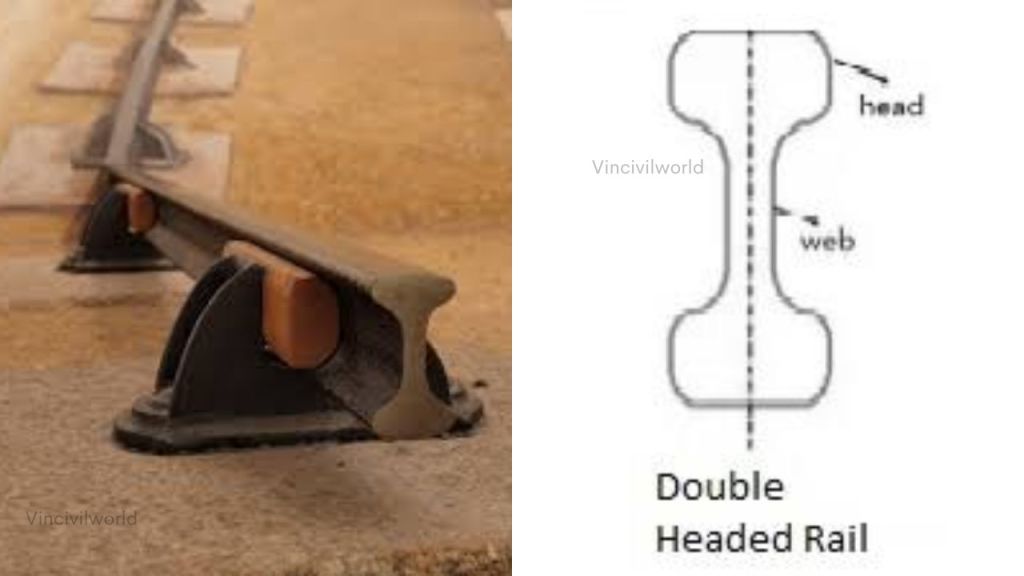
Double headed rails

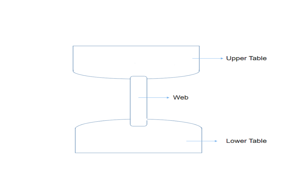
Double headed rails indicate the early stage of development. It essentially consists of three parts, such as upper table, web and lower table. Both the upper and lower tables were identical. They were introduced with the hope of doubling the life of rails.

When the upper table is worn out, the rails can be placed upside down. They can be reversed on the chair. This way, the lower table can be brought into use.

An image depicting a double headed rail fixed onto sleepers with an illustration showing the profile of a double headed rail, labeling its head and web.
Illustration of double headed rails, showcasing the upper table, web, and lower table design, along with the rail’s mounting setup.
Double headed rails
Double headed rails

But this idea soon turned out to be wrong. The continuous contact of the lower table with the chair made the surface of the lower table rough. Hence, the smooth running of the train was impossible.

Therefore, this type of rail is practically out of use. Nowadays, these rails vary in lengths from 20- 24.

The rail sections, whose foot and head are of same dimensions, are called double headed rails. In the beginning, these rails were widely used in the railway track.

The idea behind using these rails was that when the head had worn out due to rubbing action of wheels, the rails could be inverted. The rails could then be reused. But by experience, it was found that their foot could not be used as running surface because it also got corrugated under the impact of wheel loads.

Its time to meet the second type of rails which are bull headed rails.

Bull headed rails

Diagram illustrating the components of a bull headed rail, including the head, web, foot, and their connections to the sleeper, along with a cross-section of the rail design.
Diagram illustrating the structure of bull headed rails, showcasing individual components and their arrangement.
Bull headed rails
Bull headed rails

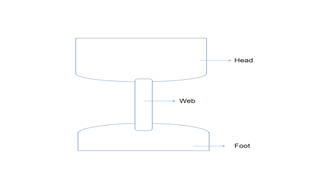
The rail section whose head dimensions are more than that of their foot are called bull headed rails. In this type of rail the head is made little thicker and stronger than the lower part by adding more metal to it. These rails also require chairs for holding them in position.

Bull headed rails are especially used for making points and crossings. This type of rail also consists of three parts, such as the head, the web and the foot. These rails were made of steel.

The head is of larger size than foot and the foot is designed only to hold up properly the wooden keys with which rails are secured. Thus, the foot is designed only to furnish necessary strength and stiffness to rails.

Two cast iron chairs are required per each sleeper when these rails are adopted. Their weight ranges from 85lb to 95lb and their length is up to 60ft.

That’s it about bull headed rails. Let’s move on to the third member in the list of types of rails, which are flat footed rails.

Flat footed rails

A flat footed rail section displayed alongside its dimensions, highlighting the head, web, and foot details, commonly used in modern railway systems.
Detailed diagram of a flat footed rail, illustrating its unique design and dimensions.
Flat footed rails
Flat footed rails

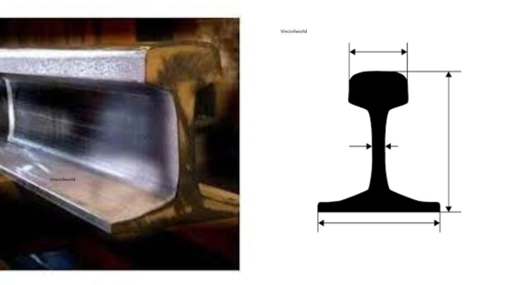
The rail sections having their foot rolled to flat are called flat footed rails. This type of rail was invented by Charles Vignola in 1836.

It was initially thought that the flat footed rails could be fixed directly to wooden sleepers. This would eliminate chairs and keys required for the BH rails. But later on, it was observed that heavy train loads caused the foot of the rail to sink into the sleepers. The heavy train loads also made the spikes loose.

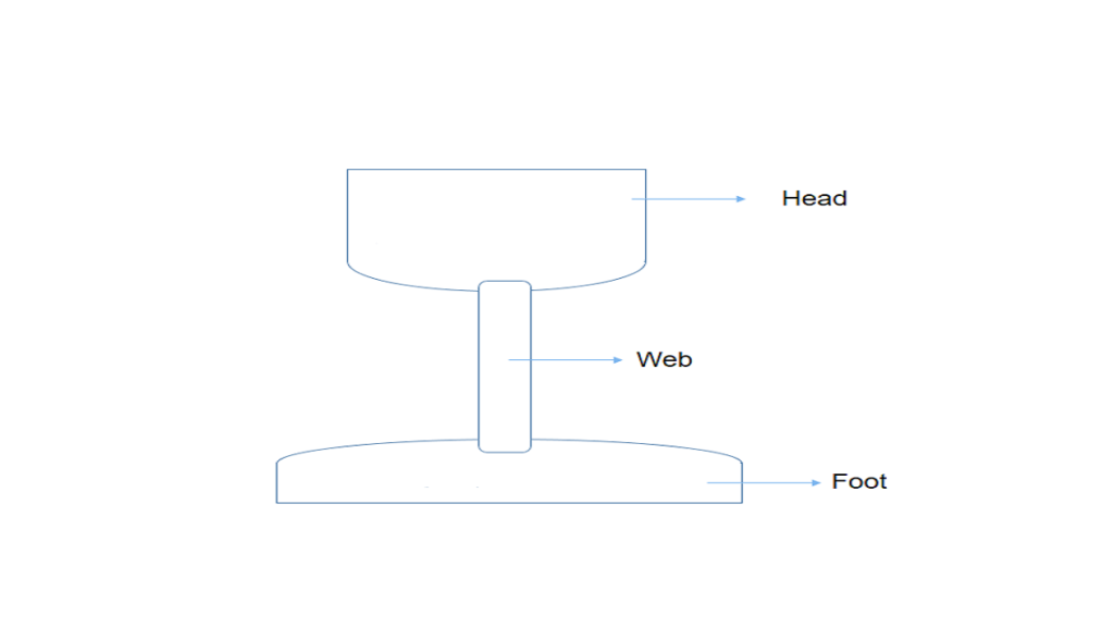
Flat footed rails consist of three parts, such as head web and foot. The foot is spread out to form a base. This form of rail has become so popular. About 90% of railway tracks in the world are laid with this form of rails.

Flat footed rails have the following advantages.

Advantages of flat footed rails

  • They do not need any chair and can be directly spiked or keyed to the sleepers. Thus they are economical.
  • They are much stiffer both vertically and laterally. The lateral stiffness is important for curves.
  • They are less liable to develop kinks and maintain a more regular top surface than bull headed rails.
  • They are cheaper than bull headed rails
  • The loads from wheels of trains are distributed over large number of sleepers and hence larger area which results in greater track stability, longer life of rails and sleepers, reduced maintenance, costs, rail failure and few interruptions to traffic

Industrial Railway Rails

Industrial railway rails are specially designed rails used in industrial environments such as factories, mines, and ports. These rails are heavier and more robust than conventional railway rails to withstand high axle loads, frequent stopping and starting, and harsh conditions. Typically, they conform to standards like the AREMA Class 1 and can weigh between 112 to 141 pounds per yard. Industrial rails provide durability, strength, and resistance to wear, ensuring reliability for transporting heavy goods and equipment within industrial premises.

Close-up view of stacked railway rails, showcasing various types including flat footed and bull headed designs, made of high-carbon steel, displaying rust and wear.
A stack of various types of railway rails, showcasing their unique designs crucial for rail infrastructure.

Crane Rails

Crane rails are specialized rails designed to support the movement of overhead cranes and gantry cranes in industrial facilities. They have a wider head and base to provide stability and distribute heavy crane loads evenly. Crane rails are typically more rigid and wear-resistant than standard rails, often stocked in weights like 60 kg/m or higher. They ensure smooth crane operation, safety, and longevity under continuous heavy loading and lateral stresses encountered in crane tracks.

The Most Used Rail Profiles Worldwide Presently

In contemporary railway engineering, the flat footed rail profile is very prevalent. It is also known as the Vignole rail. It is the most widely used rail profile globally. This profile has a flat, wide foot. It can be spiked directly to sleepers. This design eliminates the need for additional support such as chairs. Flat footed rails are favored for their structural efficiency. They are known for durability and ease of installation. This makes them ideal for standard and heavy-duty railway tracks.

Common modern flat footed rail profiles include the internationally standardized UIC60 (60 kg/m), prevalent on mainline railways worldwide, and the 115RE profile (approximately 56.9 kg/m), widely used in North America. Regional variations such as DIN rails in Europe and other heavy or light profiles also follow the flat bottom design. These flat footed/Vignole rails offer superior load distribution, enhanced stability, and cost advantages over traditional bull headed rails, leading to their dominant use in global rail infrastructure.

Image showing a close-up of a rail profile demonstrating its structure, alongside a diagram illustrating the dimensions and shape of the rail.
Illustration of flat footed rail design, showcasing its profile and structure for railway applications.

Key Takeaways

Understanding the various types of rail is essential for optimizing railway infrastructure. Types of rail sections include double-headed rails, bull-headed rails, and flat-footed rails. Double-headed rails have symmetrical upper and lower tables. They aimed to extend rail life. However, they are now rarely used due to maintenance issues. Bull-headed rails feature a thicker head for strength and are commonly used in points and crossings. Flat-footed rails, introduced by Charles Vignole, are widely adopted in modern railways due to their ease of installation and cost-efficiency. Each of these types of rail sections serves specific needs, influencing track stability and performance.

Conclusion

In conclusion, the selection of rail types profoundly affects railway system efficiency. Types of rail sections, such as double-headed rails, bull-headed rails, and flat-footed rails, each have distinct characteristics and applications. Double-headed rails are largely obsolete, while bull-headed rails remain useful for specific rail components. Flat-footed rails, with their practical advantages, dominate modern rail systems. A comprehensive understanding of the types of rail and their properties is crucial. This is essential for effective rail system design and maintenance. It ensures optimal performance and longevity.

Was the article helpful? Let me know your thoughts in the comments.

Happy learning!

MUST READ: Applications of Intelligent transportation system- everything you want to know

Cement – Ingredients and Properties

Cement ingredients and properties play a crucial role in defining the behavior and effectiveness of cement in construction applications. Cement is primarily composed of several key ingredients including lime, silica, alumina, iron oxide, magnesia, sulfur compounds, and calcium sulfate. These constituent materials, in precise cement ingredients percentage, contribute to the strength, setting time, and durability of cement. 

Portland cement composition specifically refers to the balanced ratio of these raw materials such as limestone and clay, which undergo heating to form clinker before grinding. Understanding the functions of cement ingredients is essential, as each ingredient influences important properties like hardness, color, and soundness. Together, these cement raw materials determine the overall quality and performance of cement used in construction projects.

Importance of Cement in Construction

Cement is one of the most significant structural materials used in construction. It is a binding agent that sets and hardens to adhere to building materials like sand, bricks, stone, etc. Cement is a fine powder made of limestone, clay, bauxite, and iron. When mixed with aggregates and sand, cement produces concrete; when mixed with sand alone, it produces mortar used for brickwork, plaster, flooring, etc. Cement is the most unavoidable element dominating the construction sector.

A bag of gray cement powder with a trowel resting on the surface, showcasing its fine texture and color.
This image is a close-up of a bag of cement.

Ingredients and Properties of Portland Cement

Cement ingredients and properties are fundamental to understanding how cement functions as a crucial construction material. Cement is a finely ground powder made primarily from natural raw materials. Its properties, such as strength, setting time, and durability, depend on its composition. This section introduces the importance of these ingredients, their typical proportions, and how they influence the quality and performance of cement, including the Portland cement composition and cement raw materials, in construction applications.

Portland Cement Ingredient Composition and Percentage

Cement ingredients and properties are essential for producing high-quality construction materials. The Portland cement composition consists of key cement raw materials like lime, silica, alumina, iron oxide, gypsum, and minor components. Each ingredient is present in a specific cement percentage. This directly influences essential functions of cement like strength development. It also affects setting time, durability, and hardness. Understanding how these raw materials interact chemically and physically during clinker formation provides insight into the final cement’s performance. Proper control of composition and ingredient proportions ensures optimum cement properties suitable for various construction applications.

Table displaying the main constituents and oxides of Portland cement, including ingredients and their content range percentages.
Table displaying the main constituents and oxides of Portland cement, including their ingredient proportions and ranges.

Raw Materials for Cement Manufacturing

Cement is manufactured from Lime, silica, alumina and iron oxide. Lime is obtained from limestone and oxides of silica, alumina and iron which is found in clay and shale.

Bags of cement moving along a conveyor belt in a manufacturing facility.
A conveyor belt transporting bags of cement in a manufacturing facility.

Cement Ingredients and Functions

The production of cement relies on several key raw materials: limestone, clay or shale, silica sand, and iron ore. Limestone provides calcium oxide for strength, while clay or shale supplies silica, alumina, and iron oxide. Together with other additives, these materials are processed and heated in a kiln to form clinker—the key intermediate material in cement production. This section explores the sources, preparation, and roles of these raw materials.

A cement manufacturing plant with large silos and industrial structures, set against a mountainous backdrop during twilight.
A cement manufacturing plant showcasing its large silos and processing units crucial for producing high-quality cement.

Lime

Lime is the major and main constituent of cement and which accounts to about 60-65%. Lime is the main ingredient  for production of calcium silicates aluminates and responsible for the cementing properties and strength of cement. The proportion of lime content can alter the properties of cement. Less quantity of lime can reduce the strength of cement and higher lime content can make the cement unsound. Lime in correct proportions is responsible for the strength of cement.

Close-up view of white limestone rocks used as a key ingredient in cement production.
Limestone rocks, a key raw material used in cement production, providing essential calcium oxide for strength.

Silica

SiO2 or silicon dioxide is called silica. Silica is responsible for the formation of dicalcium silicate and tricalcium silicate in reaction with lime . Right proportions of silica plays a major part in inducing cement strength.

A close-up view of a hand holding a handful of sand, showcasing its fine granules and texture.
Close-up of a hand holding fine sand, highlighting its importance as a key ingredient in cement production.

Alumina

Alumina is responsible for lowering the clinkering temperature and controlling the setting time of cement. Alumina imparts quick setting properties in cement and any increase in proportions can weaken the cement.

Iron oxide

Iron oxide is responsible for the color of the cement. It acts as a flux in the cement manufacturing process. It acts as a flux in high temperatures and combines with calcium and alumina to form tricalcium alumino ferrite which is the main ingredient behind the hardness of cement.

Magnesium oxide

Magnesium oxide is found in minor traces but increase in the quantity can reduce the strength of cement.

Sulphur Trioxide

Sulphur trioxide is available in traces but any increase can effect the cement quality.

Properties of Cement

Cement is the most significant structural material used in construction. Cement is the most recognized binding material and can be used in any nature of structures starting from a home to sky scrappers, industrial structures ,bridges, roads etc. Cement when mixed with sand and aggregates forms concrete and when mixed with sand makes mortar. The serviceability, strength and durability of a structure is purely depend on the quality of cement which is being used for concrete and mortar. The properties of cement is directly related to the proportioning of ingredients, grinding, packing etc.

Construction site with workers and heavy machinery, showing the foundation work including steel reinforcements and concrete pouring.
Construction site showing workers pouring concrete into foundations surrounded by reinforcement bars.

Physical Properties of Cement

Physical properties include fineness, setting time, soundness, and strength, influencing workability and durability. For detailed information, please refer to our blog: Physical Properties of Cement.

Key Takeaways

  • Cement ingredients and properties determine cement’s behavior and effectiveness in construction.
  • Portland cement composition involves precise proportions of limesilicaaluminairon oxidemagnesiasulfur compounds, and calcium sulfate.
  • Lime forms calcium silicates and aluminates providing essential cementing properties and strength.
  • Silica contributes to hardness and strength by forming calcium silicate compounds.
  • Alumina lowers clinker temperature and influences quick setting, but excess weakens cement.
  • Iron oxide imparts color and contributes to the cement’s hardness and strength.
  • Excess magnesium oxide and sulfur trioxide negatively affect cement quality and stability.
  • Proper cement ingredients percentage ensures optimal cement properties including strength, durability, and setting time.
  • Quality of raw materials like limestone and clay controls the Portland cement composition and performance.
  • The functions of cement ingredients collectively determine cement’s suitability for various construction applications.
  • Physical characteristics like fineness and soundness impact cement performance and concrete workability.
  • Controlled manufacturing processes ensure consistent, high-quality cement production.

Conclusion

Cement serves as a fundamental structural material in construction. Its properties are deeply influenced by its carefully controlled cement ingredients percentage. They are also influenced by Portland cement composition. The primary raw materials include lime, silica, and alumina. Iron oxide and minor components like magnesia and sulfur trioxide also contribute specific functions crucial for strength. These components affect setting time, durability, and appearance. Manufacturers must understand the role and balance of these cement raw materials. This understanding enables them to produce cement with desired properties. It is essential for diverse construction needs. Ultimately, maintaining the correct proportions and quality of raw materials ensures cement meets stringent performance standards, making it indispensable in building long-lasting, reliable structures.

Principle of surveying-First and Second Survey Principle

Two basic principle of surveying serves as the cornerstones upon which all other surveying methods are developed. Surveying is the process of determining the relative position of various points on the earth’s surface by measuring the distance between them and creating a map to any reasonable scale. The principle of surveying forms the foundation for accurate land measurement and mapping. Engineers and surveyors apply the first survey principle and second survey principle to ensure precise data collection. A system of reliable control points, established with high precision, anchors the entire survey framework and serves as fixed references for all measurements. Moreover, understanding surveying principles helps professionals establish reliable surveying control points, which are essential for consistent measurements.

Consequently, following these fundamental principles of surveying enables effective planning and execution of surveying projects. By mastering these concepts, surveyors can achieve high accuracy and efficiency in their work, ultimately contributing to successful construction and infrastructure development. Therefore, the principle of surveying and its related key concepts remain critical for the integrity of all surveying activities. In the blog Basic of civil engineering; a Simple and in-depth guide, we saw the fundamentals of surveying. Here, we will look at the fundamental principle of surveying using diagrams to make it easier to understand. So, why follow the surveying principle? Is it unavoidable? Let’s see what happens.

So, why follow the surveying principle? Is it unavoidable? Let’s see what happens.

  1. What is the principle of surveying?
  2. The fundamental principle of surveying
  3. The first principle of surveying
    1. What are control points?
    2. Importance of the first principle of surveying
  4. The second principle of surveying
    1. Taking extra care in fixing new control points
      1. what is a check line?
      2. How check lines are used to check the accuracy of the framework?
      3. What are tie lines?
      4. How do tie lines help to embed the principles of surveying?
  5. Key Takeaways
  6. Conclusion

What is the principle of surveying?

To understand the importance of the principle of surveying, we should first know the purpose of carrying out surveying. Generally, it is to make measurements of objects on, above, or beneath the ground to show their relative positions on paper. The relative position required is either horizontal, vertical, or both. Or, similarly surveying is used for the measurement of objects in their horizontal positions.

A surveying instrument set up on a tripod in the foreground, with construction workers actively working on a site in the background.
A surveying instrument set up on a construction site, highlighting the importance of accurate measurements in civil engineering.

The principle of surveying comprises two main principles are the strategies to get very accurate results. Basically, successful surveying can’t be carried out without obeying the basic principle of surveying. So, let’s sneak into the details of each of the principles that fetch you accurate results in surveying.

Related articles relating to surveying

The fundamental principle of surveying

The main principle of surveying is categorized into

  • First Principle of Surveying
  • Second Principle of Surveying

The first principle of surveying

The first principle of surveying is to work from whole to part.

To understand this, we should first know what a control point is.

What are control points?

A control point is a point on the ground or any permanent structure whose horizontal and vertical location is known.

Having this in mind, let’s dive deep into the details of the principle.

 In surveying large areas, a system of control points is identified and they are located with high precision. Then secondary control points are located using lesser precise methods. Accordingly, the details of the localized areas are measured and plotted concerning the secondary control points. This is called working from whole to part.

Importance of the first principle of surveying

  • Helps to localize errors to particular points rather than distributing them across the area.
  • Prevents the accumulation of errors, which can become unacceptable over large areas.
  • Creates a reliable and accurate control framework before surveying smaller, detailed areas.
  • Ensures accurate measurements for mapping and construction projects.
  • Allows secondary control points to be located with less precision while maintaining overall integrity.
  • Helps contain and adjust inevitable errors within the control framework.
  • Facilitates efficient surveying by starting from primary control points with high precision and adding subsidiary detail surveys.
  • Maintains the integrity and precision of surveying data for infrastructure development.
  • Reduces risk of error magnification during survey.
  • Supports clear organization of survey work, making it manageable and structured.
  • These points summarize why the first principle of surveying is critical for achieving quality, reliable, and error-controlled survey outcomes.

Moving on,

The second principle of surveying

Hope you got a clear idea about working from whole to part. Similarly, let us see what the second principle of surveying means.

The second principle of surveying states that new points (stations) must be located by at least two measurements either linear or angular from fixed control points. This redundancy ensures accuracy by verifying positions and minimizing errors. Surveyors use multiple reference points to precisely fix new stations, maintaining reliable mapping and error control throughout the survey process. This principle complements the first principle and is essential for accurate surveying and construction.

Taking extra care in fixing new control points

Survey Principle - Methods of taking care in fixing new control points
Taking extra care in fixing new control points
Diagram illustrating the methods for fixing surveying control points A, B, and C through various measurements and angles.
Diagram illustrating the methods of fixing surveying control points with respect to established points A and B.

The figure shows the various methods of fixing point C concerning already fixed points A and B by measuring sides, angles, or setting perpendiculars. For fixing new control points (stations) with respect to already fixed points at least two independent processes should be followed.

If A and B are already located control points and concerning the new control point C is to be located, apart from the minimum measurements required as shown in the above figure, one more measurement should be taken.

Measuring the lengths of check lines and tie lines will also serve this purpose as shown in the figure below.

Principle of surveying - check line and tie line
Check line and tie line
Diagram illustrating check lines and tie lines in surveying, showing the relationship between fixed points A and B and the new points C, with labeled check line and tie line.
Illustration of check lines and tie lines used in surveying to verify measurements and locate points.

So,

what is a check line?

A check line otherwise called a proof line is a line joining the apex of a triangle to some fixed points on any two sides of a triangle. A check line in surveying is the line joining the apex of a triangle to fixed points on its base, used to verify the accuracy of the survey measurements. It ensures correctness by comparing field measurements with plotted lengths, helping detect and control errors. Also called a proof line, it may be run independently to confirm the main survey lines’ precision and sometimes assists in locating interior details.

How check lines are used to check the accuracy of the framework?

The length of checking as measured on the ground should be equal to the length on the plan.Check lines are used to verify the accuracy of a surveying framework by measuring the length on the ground and ensuring it matches the corresponding length on the plan, thereby detecting errors and confirming precision.

Okay. We are done with the check lines. What about tie lines?

What are tie lines?

A tie line joints two fixed points on the main survey lines.

How do tie lines help to embed the principles of surveying?

Tie lines generally, help to check the accuracy of surveying and to locate interior details. The position of each tie line should be close to some features, such as paths, buildings, etc.

Two surveyors in safety gear analyzing blueprints while using a surveying instrument on a road.
Surveyors analyzing construction plans on site while using a total station for precise measurements.

Tie lines, on the other hand, run from the main survey lines. They locate interior or nearby details and avoid long offsets. They connect fixed points (tie stations) and help accurately position details away from main lines, enhancing the survey’s completeness and reducing measurement errors.

So, be happy that you are now savvy in the topic of surveying.

Key Takeaways

  • The two basic principles of surveying form the foundation of all surveying methods.
  • Surveying measures relative positions on the Earth’s surface by accurately determining distances and creating maps to scale.
  • The principle of surveying is essential for precise land measurement, mapping, and infrastructure development.
  • Engineers use the first principle of surveying to work from the whole to the part, establishing reliable primary control points with high precision.
  • The second principle of surveying requires locating new points by at least two measurements (linear or angular) from fixed control points to minimize errors.
  • Control points serve as fixed references, anchoring the survey framework to ensure accuracy and error control.
  • Check lines verify survey accuracy by comparing ground and plan lengths, while tie lines help locate interior details and maintain survey completeness.
  • Adhering to these principles ensures efficient, error-controlled, and reliable surveying critical for successful projects.

Conclusion

The principles of surveying are indispensable for achieving accuracy and precision in all surveying tasks within civil engineering. By systematically applying the first principle ,working from broad, reliable control points to detailed measurements and the second principle, using multiple references for new points, surveyors establish a robust control framework that localizes and minimizes errors. Control points anchor this system, ensuring consistent and dependable measurements throughout the survey. Tools like check lines and tie lines further embed these practices by validating measurement accuracy and capturing detailed site information. Mastering these principles fosters efficient planning, mapping, and execution of surveying projects, ultimately supporting high standards in construction and infrastructure development. Thus, surveying principles remain critical for the integrity and success of any surveying activity

Happy learning!

Types of Irrigation- Flow and Lift Irrigation Full Details

Types of irrigation are mainly divided into two- Lift irrigation and flow irrigation. Flow irrigation is further divided into perennial and inundation irrigation. Inundation irrigation is again subdivided into three. They are direct irrigation, storage irrigation and combined System. We are going to meet the huge family in the blog.

Irrigation is crucial for sustainable agriculture, ensuring crops receive water even when rainfall is uncertain. Two predominant systems are widely implemented today: flow irrigation and lift irrigation. In flow irrigation, water naturally moves from rivers or canals to fields by gravity. This includes inundation irrigation and perennial irrigation methods. These methods make it cost-effective and widely accessible. On the other hand, lift irrigation uses pumps or other means to raise water from lower sources. It offers solutions in areas where gravity canals can’t reach. Understanding the difference between lift irrigation and flow irrigation, the mechanics behind a flow irrigation system. This article covers all aspects, helping farmers and professionals choose the right irrigation strategy for their fields.

  1. Types of Irrigation methods
  2. Flow irrigation- Major among types of irrigation
    1. Perennial irrigation system
    2. Inundation irrigation
    3. Direct irrigation or river canal irrigation
    4. Storage irrigation
    5. Combined System
  3. Lift irrigation- second among types of irrigation
  4. Choice between types of irrigation
  5. Difference between Lift irrigation and Flow irrigation
  6. Key takeaways
  7. Conclusion 

Types of Irrigation methods

Irrigation is crucial for ensuring crops receive adequate water when rainfall is lacking. Various irrigation methods have been developed to deliver water efficiently to fields. Each method is designed to suit different landscapes. These methods also consider diverse water sources and agricultural requirements.

Irrigation is mainly two types.

  • Flow irrigation
  • Lift irrigation

The figure below is a schematic diagram showing the types of irrigation.

Types of irrigation
Types of irrigation
A schematic diagram illustrating the two main types of irrigation methods: Flow Irrigation and Lift Irrigation, with Flow Irrigation further divided into Perennial and Inundation Irrigation, and Inundation Irrigation further subdivided into Direct Irrigation, Storage Irrigation, and Combined Irrigation.
Schematic diagram illustrating the different types of irrigation methods: Flow Irrigation and Lift Irrigation.

Let’s get into each of them in detail.

Flow irrigation- Major among types of irrigation

Flow irrigation is that type of irrigation in which the supply of irrigation water available is at such a level that it is conveyed on to the land by the gravity flow. The Flow irrigation is an irrigation method where water supply is conveyed to agricultural fields by gravity flow from sources like rivers or canals, without external energy. It includes perennial irrigation and inundation irrigation, making it cost-effective and widely used. Understanding flow irrigation systems and its difference with lift irrigation is crucial for efficient water management.

  • Perennial irrigation system
  • Inundation or flood irrigation system

So, what are these? Relax. We will take one at a time and learn.

Perennial irrigation system

In perennial irrigation system, the water required for irrigation is supplied in accordance with the crop requirements throughout the crop storage. Weirs or barrages are required to store the excess water during floods and release it to the crops as and when it is required.

The perennial irrigation system supplies water continuously throughout the crop’s growth period, matching irrigation to crop needs. It uses storage structures like dams, barrages, or weirs to store excess water during floods and releases it as required. This system ensures reliable water availability year-round; consequently, it promotes steady crop growth and higher yields. Moreover, it is particularly suitable for areas with consistent water sources.

Inundation irrigation

Inundation irrigation is carried out by deep flooding and thorough saturation of the land to be cultivated which is then drained off prior to the planting of the crop.

The Inundation irrigation is a traditional method. Floodwater from a river overflow during the rainy season is diverted to agricultural land through a canal. This process occurs without any regulating structure. The canal’s bed level is fixed so water flows only when the river level exceeds it, and irrigation stops when the water level falls. Because there is no head regulator, over-irrigation may damage crops. It relies solely on gravity and natural flooding events for water supply.

Depending upon the source from which the water is drawn, inundation irrigation can be further subdivided into 3 types.

  • Direct irrigation or river canal irrigation
  • Storage irrigation
  • Combined System
Schematic diagram showing types of inundation irrigation: direct irrigation, storage irrigation, and combined irrigation.
Schematic diagram illustrating the types of inundation irrigation: Direct irrigation, Storage irrigation, and Combined irrigation.

Now, what? Let’s peep into each of them to make friends with them.

Direct irrigation or river canal irrigation

figure shows direct irrigation
Direct irrigation
A curved canal filled with water, bordered by green grass and plants, illustrating a flow irrigation system.
A canal used for direct irrigation, showcasing how water is supplied to agricultural fields using gravity flow.

We are going to jump right into the details of direct irrigation now.

  • In this direct irrigation system, water is directly diverted to the canal without attempting to store the water. For such a system, a low diversion weir or diversion barrage is constructed across the river.
  • This raises the water level in the river and thus diverts the water to the canal taking off upstream of the weir, as shown in figure.
  • Generally, a direct irrigation scheme is of a smaller magnitude, since there are no rigid controls over the supplies. One or two main canals may take off directly from the river.
  • Cross- drainage works are constructed wherever natural drains or distributary streams cross the canals. In a bigger scheme, there may be branch canal taking off from the main canal

Learnt about direct irrigation, right? Let’s move on to storage irrigation next.

Storage irrigation

figure shows storage irrigation
Storage Irrigation
An aerial view of a dam structure with water flowing through gates, surrounded by green land.
Aerial view of a dam illustrating the concept of storage irrigation, with water being retained for agricultural use.

What are we waiting for? See the basic knowledge about storage irrigation now.

  • In storage irrigation system, a solid barrier, such as a dam or a storage Weir is constructed across the river and water is stored in the reservoir or lake so formed.
  • Depending upon the water requirements of crops, or the hydroelectric power generation, and upon the flow of water in the basin at the site construction, the elevation storage curve for the reservoir is known.
  • The height of the dam is then decided from this curve, corresponding to the storage- volume required.
  • Storage irrigation scheme is comparatively of a bigger magnitude, and involves much more expenditure than a direct irrigation scheme.
  • One or two main canals take off from the reservoir. Due to the formation reservoir, some land property may be submerged to the upstream of the dam.
  • A network of canal system convey water to the agricultural fields, through various regulatory works.
  • Cross-drainage works such as aqueducts, syphon aqueducts, super passages and canal syphons are constructed wherever natural drains cross the canals

Time to meet the last member in flow irrigation system. Who’s that? Of course, combined system.

MUST READ: Concept of Green Building- 4 comprehensive concepts easy read!

Combined System

figure shows combined irrigation
Combined System

We have seen that in the storage irrigation system, water is stored in the reservoir, since the river is not perennial, while in the direct irrigation system, the river is perennial and hence the water is diverted from the river to the canal.

Aerial view of a dam and power generation facility, showcasing the water reservoir, power lines, and surrounding greenery.
Aerial view of a dam showcasing the reservoir, power generation facilities, and the surrounding landscape.

Sometimes, a combined scheme is adopted in which the water is first stored in the reservoir formed at the upstream side of the dam, and this water is used for water power generation.

The discharge from the power house is fed back into the river, to the downstream side of the dam. Thus, sufficient quantity of flow is again available in the river.

At a suitable location in the downstream, a pick up weir is constructed. This weir diverts the water from the river to the canal.

How can we leave the second main among the types of irrigation alone? Shake your hands with lift irrigation now.

Lift irrigation- second among types of irrigation

Lift irrigation is practiced when the water- supply is at too low a level to run by gravitation on to the land.

In this irrigation method, water is mechanically lifted from a lower-level source. It can be a river, well, or canal. The water is then moved to higher elevation fields using pumps or other lifting devices. Unlike gravity-fed systems, pumps carry the water first to a main delivery chamber. This chamber is at the highest point of the command area. From there, water is distributed by gravity through pipelines or canals to agricultural lands. The system is designed around topography, often dividing fields into blocks for fair water allocation. Lift irrigation is energy-intensive. It requires careful planning for distribution. However, it enables irrigation in areas lacking natural gravity flow. It expands cultivable zones and improves water access.

In such a circumstances water is lifted by mechanical means. Irrigation from wells is an example of lift irrigation, in which sub- soil water is lifted up to the surface and is then conveyed to the agricultural fields.

Now that you know all types of irrigation, how do you choose the right one for your requirement?

Choice between types of irrigation

Direct irrigation scheme is adopted in the circumstances where the river is perennial and has a normal flow throughout the irrigation season, never less at any time than the requirements of the field.

On the contrary, storage irrigation system is adopted when the river flow is either not perennial, or where flow is insufficient during certain parts of the crop season for irrigation requirements.

In a multistage river valley development, a combined storage- cum diversion scheme is more useful.

Difference between Lift irrigation and Flow irrigation

AspectFlow IrrigationLift Irrigation
Water MovementWater flows by natural gravity from higher to lower levels.Water is mechanically lifted from lower to higher elevations.
Energy RequirementMinimal; uses gravity, no pumps needed.High; requires pumps and energy (electric, diesel, solar).
Terrain SuitabilitySuitable for sloping or river command areas.Suitable for flat or elevated lands without gravity flow.
Infrastructure CostHigh initial costs due to hydraulic structures (dams, canals).Lower initial cost; no large hydraulic structures needed.
Operational CostRelatively low maintenance and energy costs.Higher energy and maintenance costs due to pumping.
Water LossesHigher losses from seepage and evaporation in open canals.Lower losses due to closed pipelines after lifting.
Water ControlLess precise; depends on natural flow and canal design.More precise; water delivery controlled via pumps/valves.
ComplexitySimple and economical system.More complex, needs technical operation and monitoring.
ExamplesPerennial and inundation irrigation.Pumping from wells, rivers, or canals to irrigate highlands.

This table highlights the core differences in mechanics, cost, terrain applicability, and water management between the two. Lift irrigation offers flexibility for challenging terrains. However, it incurs higher energy and operational costs. Flow irrigation relies on natural gravity. It is typically simpler but limited by topography.

Key takeaways

  • Irrigation is vital for sustainable agriculture, ensuring crops receive sufficient water regardless of rainfall variability.
  • Irrigation types mainly divide into Flow Irrigation and Lift Irrigation.
  • Flow irrigation uses natural gravity flow from sources like rivers or canals. It encompasses perennial irrigation (continuous supply) and inundation irrigation (seasonal flooding).
  • Inundation irrigation subdivides into direct irrigation, storage irrigation, and combined systems, depending on water source and storage method.
  • Lift irrigation mechanically raises water using pumps to higher elevation fields, then distributes it by gravity, enabling irrigation on otherwise unreachable terrain.
  • Flow irrigation is cost-effective, energy-efficient, and suited for sloping lands with reliable water sources.
  • Lift irrigation offers flexibility on flat or elevated land but requires energy and technical management.
  • Understanding the difference between lift irrigation and flow irrigation helps farmers choose the best system based on topography, water availability, and cost.

Conclusion 

Irrigation systems are essential tools for stabilizing agricultural production and managing water resources efficiently. Flow irrigation, relying on gravity-fed water movement, remains the predominant method due to its low energy requirements and suitability for perennial and seasonal water availability. Its subdivision into perennial and inundation irrigation allows adaptation to various water flow conditions. In contrast, lift irrigation addresses challenges in flat or elevated terrains where gravity flow is impossible, mechanically lifting water to irrigate diverse lands. While lift irrigation demands higher operational costs and technical expertise, it significantly expands cultivable areas. Choosing the appropriate irrigation system depends on landscape, water source reliability, infrastructure capacity, and crop requirements. Understanding these distinctions empowers farmers and water managers to optimize irrigation efficiency, conserve water, and sustain agricultural productivity under changing climatic and geographic conditions.

MUST READ: Innovative Water Conservation Methods Unlocked.

So, loved the article on types of irrigation? Let me know if i missed out anything in the comments.

Types of Cracks in Building- 14 Building Cracks Types- Causes & Prevention

Types of Cracks in Building vary widely, each indicating different causes and requiring specific prevention methods. Common cracks include hairline cracks, which are fine and mostly cosmetic. Shrinkage cracks are caused by concrete drying. Settlement cracks arise from uneven foundation movement. Structural cracks in buildings include horizontal, vertical, diagonal, and shear cracks. These can signal serious foundation or load-bearing issues. Major causes are foundation settlement, thermal movement, chemical reactions, poor workmanship, and soil movement. Understanding these crack types helps in early detection and timely repair, ensuring building safety and durability. Preventive measures like proper soil preparation, use of control joints, quality materials, and regular maintenance are essential to minimize cracking and structural damage.

This comprehensive approach leverages key terms such as crack prevention, repair methods, and building cracks to address common challenges effectively. This article discusses 14 types of building cracks. It explains their causes, such as foundation settlement and thermal movement. It also outlines effective prevention and repair methods to maintain structural integrity. These measures ensure long-lasting building safety.

  1. Main causes of different types of cracks in building
    1. Thermal Movement
      1. Preventive Measures for thermal movement
    2. Chemical Reaction
      1. Preventive Measures for the types of cracks in building
    3. Shrinkage
      1. Preventive Measures
    4. Building cracks types generated due to quantity of Cement
      1. Preventive Measures
    5. Earthquake
      1. Preventive Measures
    6. Vegetation
      1. Preventive Measures for the types of cracks in building
    7. Bad construction practices cause some types of cracks in building
      1. Preventive measures
    8. Corrosion Cracks
      1. Preventive measure
    9. Types of cracks in building due to elastic deformation
    10. Foundation movement and settlement of soil
    11. Permeability of concrete
    12. Poor Workmanship
    13. Lack Of Maintenance
    14. Types of cracks due to structural design
  2. Key Takeaways
  3. Conclusion

Main causes of different types of cracks in building

Cracks in buildings can indicate underlying issues affecting structural stability and safety. Understanding the main causes of different crack types helps in identifying proper repair and prevention strategies. Building cracks commonly result from natural forces, material behaviors, and construction practices that induce stress and movement in structures.

The main causes of different types of cracks in buildings is as follows.

  • Thermal Movement
  • Chemical Reaction
  • Shrinkage
  • Types of cracks generated due to cement quantity
  • Earthquake cracks
  • Vegetation
  • Building crack types due to bad construction practices
  • Corrosion cracks
  • Types of cracks in building due to elastic deformation
  • Foundation movement and settlement of soil
  • Permeability of concrete
  • Poor workmanship
  • Lack of maintenance
  • Type of cracks due to structural design failures

Thermal Movement

Thermal movement is a common reason for cracks in buildings. It results from the expansion and contraction of materials. These changes are caused by temperature variations. This type of movement occurs irrespective of the structure’s cross-sectional area. All parts of the structure are affected by temperature fluctuations. Thermal stresses develop when materials expand upon heating. They also develop when materials contract upon cooling. This can induce tensile or shear stresses, leading to cracks. These cracks typically appear near points of restraint. These include joint lines, window heads, or structural columns. Movement is hindered at these points.

Preventive Measures for thermal movement

Joints need to be built like construction joints, expansion joints, control joints and slip joints.

Chemical Reaction

  • There are chances of chemical reactions to occur because of the materials used to build the concrete or materials.
  • Cracks might develop in concrete periodically. This occurs due to expansive reactions developing between aggregate with active silica and alkalis. These alkalis come from cement hydration, admixtures, or external sources.

Preventive Measures for the types of cracks in building

If sulphate content in soil is greater than 0.2 percent or in ground water exceed 300 ppm, leverage very dense concrete and either increase richness of mix to 1:1/5:3.

Shrinkage

Most building materials, especially cementitious ones, absorb moisture from the atmosphere and expand, then shrink upon drying. Excessive water in the mortar or concrete mix leads to shrinkage cracks. These are further worsened by the heat of cement hydration. Poor curing practices also aggravate these cracks. These cracks are often hairline. They occur shortly after construction. As the water evaporates from the mix, it causes volume reduction and tensile stresses.

Preventive Measures

Use minimum quantity of water for mixing cement concrete or cements mortar according to water to cement ratio .

Building cracks types generated due to quantity of Cement

Building cracks types : Due to cement quantity
A close-up view of a wall showing various cracks, indicating potential structural issues.
Cracks in a wall indicating potential structural issues due to thermal movement or settlement.

The proportion should be such that the cement in the mix is optimum. Higher the cement, greater the shrinkage/drying.

Preventive Measures

Do not use excessive cement in the mortar mix.

Earthquake

Crack happens because of the rapid shift in lower layer of the earth.

Preventive Measures

Build the foundation of building on firm ground. Tie up the building at base level, door level and roof level with connecting beams.

We covered the first five types of cracks in building. Good to have you here. Let’s move on to the remaining.

Vegetation

  • Due to the expansive action of root growing under the base, fast growing trees may often cause cracks in walls in the area around the walls.
  • Also, due to moisture contained by roots, cracks occur in clay soil.

Also read: Concept of green building- 4 comprehensive concepts easy read!

Preventive Measures for the types of cracks in building

Do not plant trees too close to the house. If they start growing in or near walls, remove any saplings from the trees as quickly as possible.

Bad construction practices cause some types of cracks in building

Building crack types : Bad construction practice
Close-up of a significant crack in the exterior wall of a building, indicating potential structural issues.
A close-up view of a structural crack on a building’s exterior wall, indicative of potential bad construction practices
  • Owing to indifference, carelessness, greed or incompetence, there is a general lack of good building practices
  • It is certainly vital for the building agency and the owner to ensure high quality material selection and good construction practices for a safe building.

Preventive measures

At the time of construction, careful inspection and use of materials of high quality is required.

Corrosion Cracks

  • The pH level of the concrete under normal conditions is high (above 12.5).
  • The high concrete pH allows for the formation of an inactive layer of ferric oxide around the reinforcement, avoiding corrosion.
  • The reinforced steel has two important causes of corrosion: chloride penetration and carbonation.
  • Penetration of chloride decreases the concrete’s pH level as oxygen, chlorides, and moisture both enter the concrete.

Preventive measure

As per IS 456-2000, use acceptable covers. When mixing concrete, use potable water.

Types of cracks in building due to elastic deformation

  • In different sections, unevenly loaded walls experience enormous variations in stress that cause cracks in walls.
  • Different shear stresses in these materials result in cracks at the junction when two building materials like masonry, concrete, steel, etc.
  • with broadly different elastic properties are constructed together under the impact of load.
  • In a building’s structural elements, dead and living loads cause elastic deformation.
  • The amount of deformation depends significantly on the material’s elastic modulus, the loading magnitude and the component dimensions.

Foundation movement and settlement of soil

  • Shear cracks occur in the base due to enormous differential settlement. Structures built on expansive soils that are susceptible to swelling due to changes in soil moisture content are highly susceptible to cracking when absorbing moisture and shrinking when drying.

Permeability of concrete

  • The process of corrosion in concrete begins with the penetration of many aggressive agents and is a significant cause of wall cracks.
  • Essentially, the ability of concrete to withstand weathering action, chemical attack or some other degradation mechanism is dictated.
  • Low permeability is thus the primary factor in concrete resilience.
  • Concrete permeability, water-cement ratio, curing, air voids due to poor compaction, use of admixtures, micro-cracks due to loading, cyclic exposure to thermal variations, and concrete ageing are influenced by several factors.
  • Cement mixture permeability is a feature of the water-cement ratio due to high-quality materials, sufficient proportioning, and good construction practice.
  • Concrete permeability is a direct result of the interconnection and porosity of the cement paste pores.

Poor Workmanship

Building cracks types due to poor workman ship
Construction worker building a structure
A close-up view of a cracked ceiling, showing a prominent diagonal crack where the ceiling meets the wall, indicating poor workman ship
An example of a significant crack in a ceiling, potentially indicating structural issues in the poor workmanship
  • The lower mixing of building materials such as sand, cement and concrete, creates cracks on walls, slabs, beams, etc.
  • Bad workmanship typically results from a lack of proper oversight, incompetence, neglect, and many others, or a mixture of all of these.

Lack Of Maintenance

  • It is necessary to take good care of your home at all times, and this can be achieved by doing routine maintenance work.
  • This means the foundation of the building remains intact and it also contributes to its lifetime.

Time to meet the last cause. Its the structural design of the structure.

Types of cracks due to structural design

  • Poor or bad structural design and specifications are another striking causes of the cracks in buildings made of majorly concrete.
  • The designer needs to consider all the environmental aspects which include soil investigations, this will enable the designer to come up with a properly robust design of the foundation.

In nutshell, each type of cracks have to be analysed and proper treatment methods and retrofits have to be adopted to restore the structure to last long.

Key Takeaways

  • Types of cracks in buildings include hairline, shrinkage, settlement, horizontal, vertical, diagonal, and shear cracks, each indicating specific structural or material issues.
  • Major causes are foundation settlement, thermal movement, chemical reactions, poor workmanship, soil movement, and bad construction practices.
  • Thermal movement causes cracks due to expansion and contraction of materials under temperature changes; chemical reactions like alkali-silica cause internal pressure cracking.
  • Shrinkage cracks arise from drying of concrete, excess water in mix, and poor curing.
  • Excess cement in mixtures increases drying shrinkage leading to cracks.
  • Earthquakes cause rapid ground shifts producing wide cracks from dynamic loads.
  • Vegetation roots exert pressure disrupting soil and foundations, causing cracks.
  • Poor workmanship such as improper mixing, low-quality materials, and negligent construction leads to cracking.
  • Corrosion from chloride penetration and carbonation lowers concrete pH, causing reinforcement deterioration and cracks.
  • Foundation movement and soil settlement induce differential stresses resulting in soil and shear cracks.
  • Prevention depends on proper foundation design, soil preparation, quality materials, control joints, and routine maintenance.

Conclusion

Understanding the various types of building cracks and their root causes is crucial for ensuring structural safety and durability. Cracks not only diminish a building’s aesthetic value but also can severely impact its integrity if left untreated. Major contributing factors include thermal movements, chemical reactions, soil settlement, poor workmanship, and inadequate structural design. Proper site and foundation preparation can significantly reduce crack formation. The use of expansion and control joints is important. Employing quality building materials also helps. Skilled workmanship is essential. Moreover, routine inspections and timely maintenance help detect early signs of cracking and allow prompt repairs, thereby extending the building’s lifespan. Ultimately, a multidisciplinary approach involving design, construction, and maintenance optimizes crack prevention and sustains long-term building performance and safety.

Hope the article could educate you on the types of cracks in building, the main causes and preventive measures. Let me know if you have any doubts in the comments.

Happy learning!

Key Physical Properties of Cement Explained

Physical properties of cement determine its performance, durability, and suitability for construction. These properties—such as fineness, setting time, soundness, strength, and consistency—play a vital role in every stage of a project, from mixing to final strength development. Engineers and builders closely evaluate these characteristics to ensure the cement meets specific standards and performs reliably under different conditions. Understanding physical properties helps in selecting the right type of cement for various applications, optimizing workability, and predicting the longevity of concrete structures. In this article, we delve into the key physical properties of cement, explore their significance in construction, and highlight the essential tests used to assess cement quality for safe and lasting building solution.

The physical properties of cement have a significant impact on a structure’s serviceability, strength, and durability. The most important and highly recognized structural material used in construction is cement. All types of construction, from large skyscrapers, bridges, and tunnels to modest residential structures, use cement. It stands out as a crucial component of industrial buildings such as power plants, refineries, steel plants, cement mills, bridges, and other infrastructure.

  1. Why are the physical properties of cement important?
  2. Physical Properties of Cement
    1. The fineness of cement – Physical properties of cement
    2. The soundness of cement – Physical Properties of Cement
      1. Causes of Unsoundness of cement
    3. Consistency of cement
    4. Strength of cement
    5. Setting time of cement
    6. Hydration of cement
  3. Key Takeaways
  4. Conclusion

Why are the physical properties of cement important?

Cement, when mixed with sand and aggregates, forms concrete, and when combined with sand alone, it results in mortar. The serviceability, strength, and durability of any structure rely significantly on the quality of cement used in both concrete and mortar. The various physical properties of cement such as setting time, strength, fineness, and soundness are crucial determinants of construction performance. These properties are directly influenced by the cement manufacturing process, which includes the precise proportioning of ingredients, thorough grinding, packaging, and proper storage of cement. Maintaining high standards throughout manufacturing ensures the cement possesses optimum properties that contribute to long-lasting, reliable, and safe concrete and mortar in construction projects.

The cement properties are classified into PHYSICAL PROPERTIES and CHEMICAL PROPERTIES

Physical Properties of Cement

The physical properties of cement are critical in ensuring cement quality. Let us explore the physical properties of cement in depth. Physical properties distinguish different cement blends used in construction. Some critical parameters influence cement quality. Good cement has the following physical properties and is based on the following factors.

Physical properties of cement
  • Fineness of Cement
  • Soundness of cement
  • Consistency of cement
  • Strength of cement
  • Setting time of Cement
  • Hydration reaction of cement

The fineness of cement – Physical properties of cement

The Fineness of cement is the measure of the particles of cement or the specific surface area of cement. The hydration rate of cement is directly related to its fineness. The higher the fineness of cement higher the specific surface area available per unit volume of cement. ie More area is available for cement and water action (hydration). This increases the rate of hydration and early gaining of strength in concrete. Bleeding can also be reduced by an increase in the fineness of the cement. But this in turn leads to dry shrinkage which can be managed by using more water.

Fineness can be determined by using a sieve analysis test, air permeability test or a sedimentation method.

The soundness of cement – Physical Properties of Cement

Soundness refers to the ability of hardened cement paste not to shrink or expand and retains its volume. If there is any change in volume, cracks may develop and the cement can be distinguished as unsound cement. Unsound cement can affect the durability and life of the structure. Soundness can also be defined as the volume stability of cement.

The cement manufacturing quality also has a very serious impact on cement quality. Inadequate heating can leave excess lime in cement. Even though cement plants have full-fledged quality labs to check the ingredients in detail, still cement has to be checked for its soundness before being used for any structure. Le Chatelier apparatus is used to test the soundness of cement.

Physical properties of cement : Soundness

Causes of Unsoundness of cement

The soundness of cement is affected by the presence of excess lime and magnesia. The excess lime hydrates very slowly to form slaked lime and will affect the properties of cement. The hydration difference between free lime (CaO) and slaked lime can change the volume of concrete on hardening and these changes make cement unsound.

Excess magnesia also reacts with water and affects the hydration process making cement unsound.

Gypsum is added to control the setting time of cement. Excess gypsum can react with Tricalcium aluminate to form calcium sulphoaluminate which can expand the concrete while hardening. The addition of gypsum has to be done with utmost care or else can make the cement unsound.

Consistency of cement

The consistency of cement is the ability of cement-water paste to flow under normal conditions. The optimum water-cement ratio has to be maintained in dry mixes to make it workable. Consistency of cement is the measure of the optimum water-cement ratio of a cement paste which can allow a Vicat apparatus plunger to penetrate a depth of 5-7 mm measured from the bottom of the mould. In that case, we can consider the paste is at normal consistency. The optimum water percentage for normal consistency ranges from 26% – 33%. The standard consistency test is conducted using a Vicat apparatus.

Consistency of cement

Strength of cement

Cement is the material responsible for imparting strength to mortar and concrete. The cement hydrates react with water and induce strength in concrete. The strength of cement has to be checked before it can be used for work. The strength can be affected by a lot of factors like water-to-cement ratio, ingredient proportioning, curing conditions, age, etc. The cement has to be checked for compressive, tensile, and flexural strength. The strengths are measured as grades in the cement bags

The strength is determined by checking the compressive strength of the cement.

Setting time of cement

The setting time of cement starts when water is added to the cement. It continues to the point where the cement reacts with water and the paste hardens. This period covers the time from production to hardening. It involves activities like mixing, conveying, placing, and hardening. The setting time depends on a lot of factors. These include the fineness of cement, water-cement ratio, chemical content, and the presence of admixtures. The setting time needs to be adjusted according to the structural requirements. It must ensure that the initial settling time is not too low. Additionally, the final setting time should not be too high.

The initial setting time is when the mix starts to stiffen and attains its plasticity. The initial setting time is 30 minutes for cement.

Setting time of cement

The final setting time is when the cement hardens to a point where it can take loads. The final setting time is 10 hours.

Hydration of cement

For using cement in any construction work, it is necessary to mix cement with water. On mixing water with the cement, a chemical reaction happens between water and cement leading to heat generation. This process of heat generation is known as the heat of hydration. It is very critical in mass concrete work and works done in hot and humid conditions.

When water is added to cement, a chemical reaction takes place between cement and water and is called hydration. Hydration generates heat, which can control the quality of the cement and helps in maintaining curing temperature in cold conditions. When used in mass concrete, heat generation tends to be very high. This can cause undesired stresses in the structure. The heat of hydration is influenced mostly by the presence of C3S and C3A in cement. It is also affected by the water-cement ratio, fineness, and curing temperature. The heat of hydration of Portland cement is calculated by finding the difference between the dry cement and the partially hydrated cement.

Heat of hydration process

Key Takeaways

  • Physical properties of cement—such as fineness, setting time, soundness, consistency, and strength—directly impact concrete’s performancedurability, and workability.
  • Fineness of cement controls the rate of hydration, early strength gain, and bleeding in concrete.
  • Soundness of cement ensures volume stability, preventing cracks and structural failures.
  • Consistency of cement relates to optimum water-cement ratio for good workability and determines appropriate mixing.
  • Cement strength (compressive, tensile, flexural) must be checked before use, as it’s fundamental for structural integrity.
  • Setting time of cement guides work timing; initial setting should not be too short, nor final setting too long, to meet construction requirements.
  • Heat of hydration (from the hydration process) is critical in mass concrete and is affected by cement composition and curing conditions.
  • Regular testing like sieve analysis, Le Chatelier apparatus, and Vicat apparatus is essential for quality control.
  • Understanding these properties helps in selecting the right cement type, optimizing construction processes, and predicting concrete longevity.

Conclusion

To achieve durable, strong, and reliable concrete structures, engineers, architects, and builders need to understand the key physical properties of cement. Properties such as fineness, soundness, and consistency are crucial. Strength, setting time, and the heat of hydration also play a vital role at every stage of construction, from mixing to final curing. Proper testing—using methods like sieve analysis, Le Chatelier, and Vicat apparatus—ensures cement meets required quality standards, which directly influences structural performance and safety. By carefully analyzing and controlling these key physical parameters, professionals can prevent common issues such as cracking, shrinkage, and poor durability. Ultimately, selecting the right type of cement based on its physical characteristics optimizes workability, enhances longevity, and assures a superior building solution for any project.