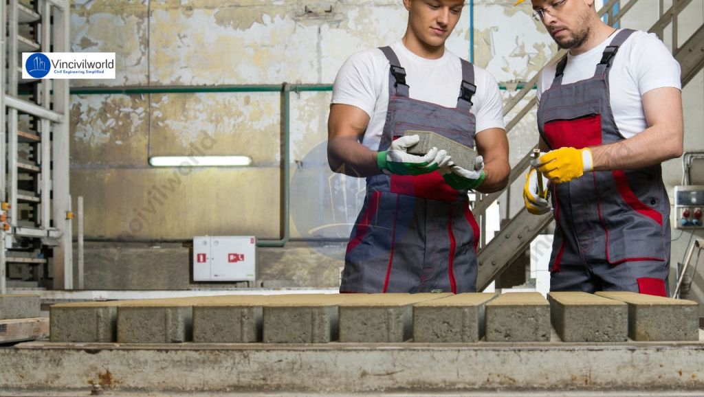
Physical properties of cement determine its performance, durability, and suitability for construction. These properties—such as fineness, setting time, soundness, strength, and consistency—play a vital role in every stage of a project, from mixing to final strength development. Engineers and builders closely evaluate these characteristics to ensure the cement meets specific standards and performs reliably under different conditions. Understanding physical properties helps in selecting the right type of cement for various applications, optimizing workability, and predicting the longevity of concrete structures. In this article, we delve into the key physical properties of cement, explore their significance in construction, and highlight the essential tests used to assess cement quality for safe and lasting building solution.
The physical properties of cement have a significant impact on a structure’s serviceability, strength, and durability. The most important and highly recognized structural material used in construction is cement. All types of construction, from large skyscrapers, bridges, and tunnels to modest residential structures, use cement. It stands out as a crucial component of industrial buildings such as power plants, refineries, steel plants, cement mills, bridges, and other infrastructure.
Why are the physical properties of cement important?
Cement, when mixed with sand and aggregates, forms concrete, and when combined with sand alone, it results in mortar. The serviceability, strength, and durability of any structure rely significantly on the quality of cement used in both concrete and mortar. The various physical properties of cement such as setting time, strength, fineness, and soundness are crucial determinants of construction performance. These properties are directly influenced by the cement manufacturing process, which includes the precise proportioning of ingredients, thorough grinding, packaging, and proper storage of cement. Maintaining high standards throughout manufacturing ensures the cement possesses optimum properties that contribute to long-lasting, reliable, and safe concrete and mortar in construction projects.
The cement properties are classified into PHYSICAL PROPERTIES and CHEMICAL PROPERTIES
Physical Properties of Cement
The physical properties of cement are critical in ensuring cement quality. Let us explore the physical properties of cement in depth. Physical properties distinguish different cement blends used in construction. Some critical parameters influence cement quality. Good cement has the following physical properties and is based on the following factors.
The fineness of cement – Physical properties of cement
The Fineness of cement is the measure of the particles of cement or the specific surface area of cement. The hydration rate of cement is directly related to its fineness. The higher the fineness of cement higher the specific surface area available per unit volume of cement. ie More area is available for cement and water action (hydration). This increases the rate of hydration and early gaining of strength in concrete. Bleeding can also be reduced by an increase in the fineness of the cement. But this in turn leads to dry shrinkage which can be managed by using more water.
Fineness can be determined by using a sieve analysis test, air permeability test or a sedimentation method.
The soundness of cement – Physical Properties of Cement
Soundness refers to the ability of hardened cement paste not to shrink or expand and retains its volume. If there is any change in volume, cracks may develop and the cement can be distinguished as unsound cement. Unsound cement can affect the durability and life of the structure. Soundness can also be defined as the volume stability of cement.
The cement manufacturing quality also has a very serious impact on cement quality. Inadequate heating can leave excess lime in cement. Even though cement plants have full-fledged quality labs to check the ingredients in detail, still cement has to be checked for its soundness before being used for any structure. Le Chatelier apparatus is used to test the soundness of cement.
Physical properties of cement : Soundness
Causes of Unsoundness of cement
The soundness of cement is affected by the presence of excess lime and magnesia. The excess lime hydrates very slowly to form slaked lime and will affect the properties of cement. The hydration difference between free lime (CaO) and slaked lime can change the volume of concrete on hardening and these changes make cement unsound.
Excess magnesia also reacts with water and affects the hydration process making cement unsound.
Gypsum is added to control the setting time of cement. Excess gypsum can react with Tricalcium aluminate to form calcium sulphoaluminate which can expand the concrete while hardening. The addition of gypsum has to be done with utmost care or else can make the cement unsound.
Consistency of cement
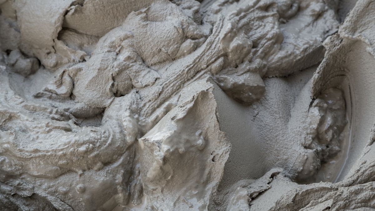
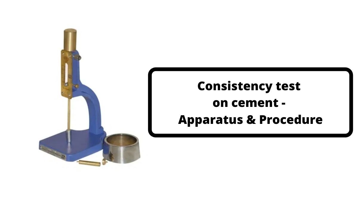
The consistency of cement is the ability of cement-water paste to flow under normal conditions. The optimum water-cement ratio has to be maintained in dry mixes to make it workable. Consistency of cement is the measure of the optimum water-cement ratio of a cement paste which can allow a Vicat apparatus plunger to penetrate a depth of 5-7 mm measured from the bottom of the mould. In that case, we can consider the paste is at normal consistency. The optimum water percentage for normal consistency ranges from 26% – 33%. The standard consistency test is conducted using a Vicat apparatus.
Consistency of cement
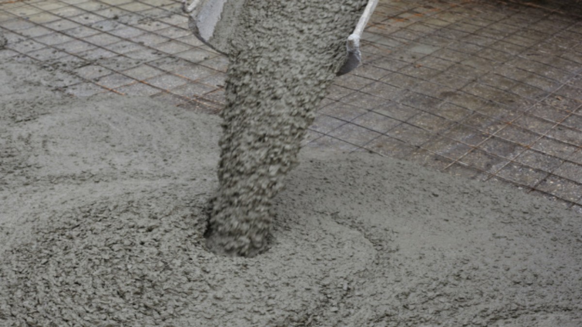
Strength of cement
Cement is the material responsible for imparting strength to mortar and concrete. The cement hydrates react with water and induce strength in concrete. The strength of cement has to be checked before it can be used for work. The strength can be affected by a lot of factors like water-to-cement ratio, ingredient proportioning, curing conditions, age, etc. The cement has to be checked for compressive, tensile, and flexural strength. The strengths are measured as grades in the cement bags
The strength is determined by checking the compressive strength of the cement.
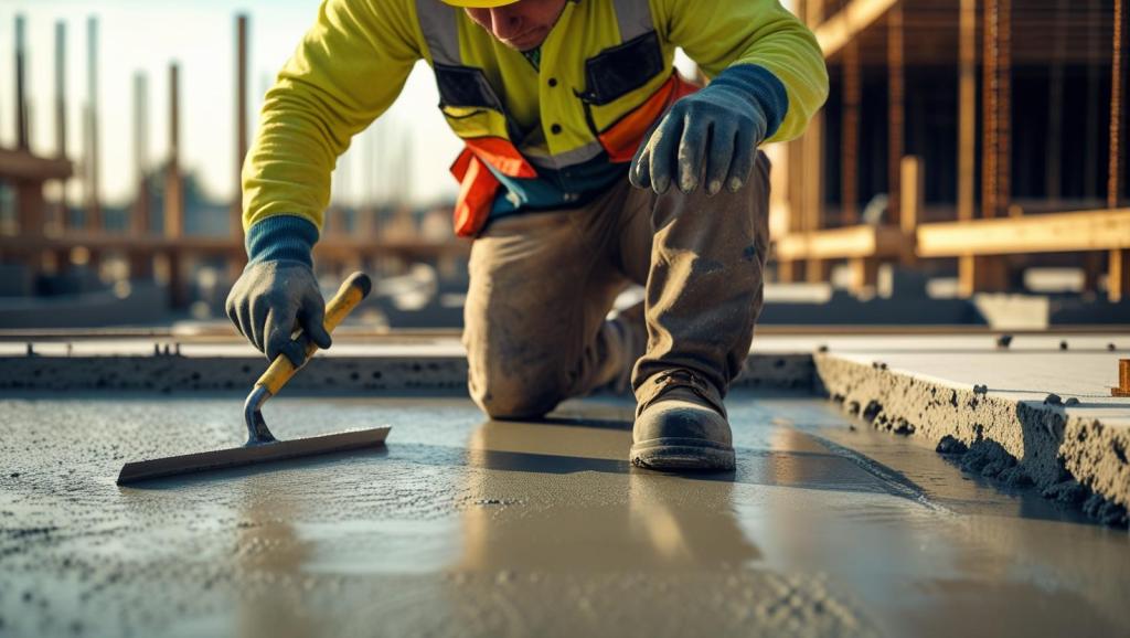
Setting time of cement
The setting time of cement starts when water is added to the cement. It continues to the point where the cement reacts with water and the paste hardens. This period covers the time from production to hardening. It involves activities like mixing, conveying, placing, and hardening. The setting time depends on a lot of factors. These include the fineness of cement, water-cement ratio, chemical content, and the presence of admixtures. The setting time needs to be adjusted according to the structural requirements. It must ensure that the initial settling time is not too low. Additionally, the final setting time should not be too high.
The initial setting time is when the mix starts to stiffen and attains its plasticity. The initial setting time is 30 minutes for cement.
Setting time of cement
The final setting time is when the cement hardens to a point where it can take loads. The final setting time is 10 hours.
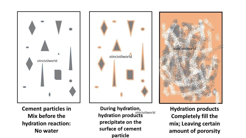
Hydration of cement
For using cement in any construction work, it is necessary to mix cement with water. On mixing water with the cement, a chemical reaction happens between water and cement leading to heat generation. This process of heat generation is known as the heat of hydration. It is very critical in mass concrete work and works done in hot and humid conditions.
When water is added to cement, a chemical reaction takes place between cement and water and is called hydration. Hydration generates heat, which can control the quality of the cement and helps in maintaining curing temperature in cold conditions. When used in mass concrete, heat generation tends to be very high. This can cause undesired stresses in the structure. The heat of hydration is influenced mostly by the presence of C3S and C3A in cement. It is also affected by the water-cement ratio, fineness, and curing temperature. The heat of hydration of Portland cement is calculated by finding the difference between the dry cement and the partially hydrated cement.
Heat of hydration process
Key Takeaways
Physical properties of cement—such as fineness, setting time, soundness, consistency, and strength—directly impact concrete’s performance, durability, and workability.
Fineness of cement controls the rate of hydration, early strength gain, and bleeding in concrete.
Soundness of cement ensures volume stability, preventing cracks and structural failures.
Consistency of cement relates to optimum water-cement ratio for good workability and determines appropriate mixing.
Cement strength (compressive, tensile, flexural) must be checked before use, as it’s fundamental for structural integrity.
Setting time of cement guides work timing; initial setting should not be too short, nor final setting too long, to meet construction requirements.
Heat of hydration (from the hydration process) is critical in mass concrete and is affected by cement composition and curing conditions.
Regular testing like sieve analysis, Le Chatelier apparatus, and Vicat apparatus is essential for quality control.
Understanding these properties helps in selecting the right cement type, optimizing construction processes, and predicting concrete longevity.
Conclusion
To achieve durable, strong, and reliable concrete structures, engineers, architects, and builders need to understand the key physical properties of cement. Properties such as fineness, soundness, and consistency are crucial. Strength, setting time, and the heat of hydration also play a vital role at every stage of construction, from mixing to final curing. Proper testing—using methods like sieve analysis, Le Chatelier, and Vicat apparatus—ensures cement meets required quality standards, which directly influences structural performance and safety. By carefully analyzing and controlling these key physical parameters, professionals can prevent common issues such as cracking, shrinkage, and poor durability. Ultimately, selecting the right type of cement based on its physical characteristics optimizes workability, enhances longevity, and assures a superior building solution for any project.
Civil construction companies play a crucial role in shaping the built environment across Australia. Their expertise spans a wide variety of projects, both public and private, each requiring specific skills, resources, and regulatory compliance. Understanding the types of projects a civil construction firm can deliver helps in appreciating the breadth and value they bring to infrastructure development.
Public sector civil construction projects are funded and commissioned by local, state, or federal government bodies. These initiatives are often large-scale and aimed at improving community infrastructure, safety, and accessibility.
Transport Infrastructure Civil construction firms are extensively involved in building and upgrading roads, highways, bridges, tunnels, and railways. Projects like the WestConnex motorway in Sydney or the Melbourne Metro Tunnel are prime examples of large-scale public investments delivered by civil contractors.
Water and Sewerage Systems Governments frequently engage a civil construction company for the development and maintenance of water supply and wastewater treatment infrastructure. These include dams, pumping stations, pipelines, and desalination plants, all essential for supporting urban and regional populations.
Public Buildings and Facilities While often associated with vertical construction, civil companies may be contracted for the site preparation and structural components of hospitals, schools, airports, and sporting facilities. Civil works can involve everything from earthmoving and grading to laying foundations and drainage systems.
Parks and Recreational Infrastructure Enhancing liveability in urban areas, councils and state governments invest in parks, pathways, and open spaces. Civil construction is responsible for landscaping, storm water management, and pathway construction within these developments.
Private Sector Projects
Private sector civil construction projects are commissioned by businesses, developers, or private individuals. These projects can range in scale and are usually driven by commercial objectives, timelines, and cost-efficiency.
Residential and Commercial Developments Civil contractors prepare land for housing estates, apartment complexes, and commercial premises. Services include bulk earthworks, road access, utility installation, and stormwater management. These foundational services are critical for enabling vertical construction to proceed safely and efficiently.
Industrial Facilities Mines, factories, logistics hubs, and warehouses often require tailored civil solutions. Construction companies in this space may be tasked with building haul roads, laying heavy-duty pavements, or constructing retaining walls and site drainage systems to support heavy machinery and operations.
Renewable Energy Projects With Australia’s growing investment in renewables, civil firms are increasingly engaged in the construction of wind farms, solar arrays, and battery storage facilities. Their role typically involves site levelling, road access creation, and the installation of cable trenches and foundations.
Private Infrastructure Upgrades Large corporations may contract civil contractors to upgrade internal roads, car parks, or underground services on their campuses or facilities, enhancing safety and capacity.
Whether in the public or private sector, civil construction companies provide the backbone for physical infrastructure in Australia. Their ability to deliver diverse projects—from motorways and water treatment plants to industrial access roads and renewable energy infrastructure, makes them indispensable to national development and economic growth. By leveraging engineering know-how, regulatory understanding, and modern construction methods, these companies continue to shape Australia’s future.
Types of bonds in brick masonry commonly used in construction are detailed in this article. The process of bonding bricks with mortar in between them is known as brick masonry. Bricks are arranged in a pattern to maintain their aesthetic appearance and strength. This article is about the various types of bonds in brick masonry walls.
Brickwork bonding types play a crucial role in the strength, stability, and appearance of masonry structures. Brick bonds are significant in residential walls, boundary fences, or historical buildings. The pattern in which bricks are laid affects both structural performance and aesthetics. Understanding various brick bonds types is essential for builders and architects. They can choose the right layout for load-bearing capacity. The right layout enhances visual appeal and improves construction efficiency. Common types of brick bonds include Stretcher Bond, Header Bond, English Bond, and Flemish Bond. The right bond also improves construction efficiency, especially when working with materials like Masonry stone. Each type serves different functional purposes. They also cater to various design needs. This article explores the major brickwork bonding types, explaining their features, advantages, and typical applications. By mastering these patterns, professionals can ensure durable and visually pleasing brickwork in any construction project.
Bricks are rectangular construction materials. Bricks are commonly used in the construction of walls, paving, and other structures. They are also inexpensive and simple to work with.
There are different types of brick masonry bonds. They are
Stretcher Bond
Header Bond
English Bond
Flemish Bond
Raking bond
Zigzag Bond
Herring-Bone Bond
Facing Bond
Dutch Bond
Diagonal Bond
Rattrap bond
Let us have a look at the most commonly used types of bonds in brick masonry.
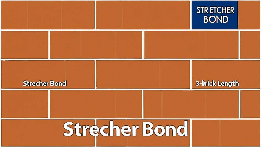
Stretcher bond – Types of Bonds in brick masonry
The stretcher is the brick’s lengthwise face or otherwise known as the brick’s longer, narrower face, as shown in the elevation below. Bricks are laid so that only their stretchers are visible, and they overlap halfway with the courses of bricks above and below. Accordingly, In this type of brick bond, we lay the bricks parallel to the longitudinal direction of the wall. In other words, bricks are laid as stretchers in this manner. It is also referred to as a walking bond or a running bond. Additionally, it is among the simplest and easiest brick bonds.
Stretcher Bond – Types of bond in brick masonry
Limitations of Stretcher bonds
Stretcher bonds with adjacent bricks, but they cannot be used to effectively bond with them in full-width thick brick walls.
They are only suitable for one-half brick-thick walls, such as the construction of a half-brick-thick partition wall.
Stretcher bond walls are not stable enough to stand alone over longer spans and heights.
Stretcher bonds require supporting structures such as brick masonry columns at regular intervals.
Applications of stretcher bonds
Stretcher bonds are commonly used as the outer facing in steel or reinforced concrete-framed structures. These are also used as the outer facing of cavity walls. Other common applications for such walls include boundary walls and garden walls
Header bond – Type of Bonds in brick masonry
Generally for header bond, the header is the brick’s width wise face. In brick masonry, a header bond is a type of bond in which bricks are laid as headers on the faces. It’s also referred to as the Heading bond. The header is the brick’s shorter square face, measuring 9cm x 9cm. As a result, no skilled labour is required for the header bond’s construction. While stretcher bond is used for half brick thickness walls, header bond is used for full brick thickness walls that measure 18cm. Generally, in the case of header bonds, the overlap is kept equal to half the width of the brick. To achieve this, three-quarter brickbats are used in alternate courses as quoins.
Header bond – Brick bond types
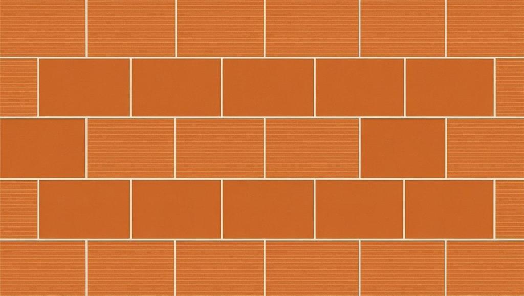
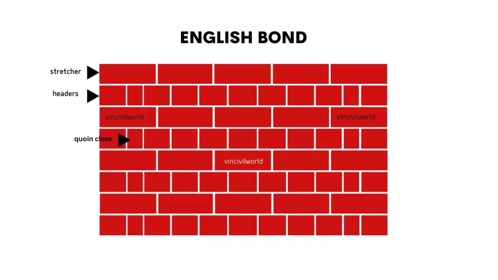
English Bond – Types of bonds in brick masonry
English bond uses alternative courses of stretcher and headers. It is the strongest and most commonly used bond in brick masonry. A quoin closer is used at the beginning of a wall. It is also used at the end of a wall after the first header. This breaks the continuity of vertical joints. Mostly, a quoin close is a brick that has been cut lengthwise into two halves and is used at corners in brick walls. Similarly, each alternate header is centrally supported over a stretcher.
Types of bonds in brick masonry – English bond
Flemish Bond
In Flemish bond, each course is a combination of header and stretcher. Accordingly, the header is supported centrally over the stretcher below it. Generally, closers are placed in alternate courses next to the quoin header to break vertical joints in successive layers. Flemish bond, also known as Dutch bond, is made by laying alternate headers and stretchers in a single course. The thickness of Flemish bond is minimum one full brick.The drawback of using Flemish bond is that it requires more skill to properly lay because all vertical mortar joints must be aligned vertically for best results. Closers are placed in alternate courses next to the quoin header to break vertical joints in successive There are two types of Flemish bond
Double Flemish bond
Single Flemish bond
Double flemish bond
The double flemish bond has the same appearance on both the front and back faces. As a result, this feature gives a better appearance than the English bond for all wall thicknesses.
Single Flemish Bond
The English bond serves as the backing for a single Flemish bond, which also includes a double Flemish bond on its facing. As a result, both the English and Flemish bonds’ strengths are utilised by the bond. Similarly, this bond can be used to build walls up to one and a half brick thick. However, high-quality, expensive bricks are used for the double-Flemish bond facing. Cheap bricks in turn can be used for backing and hearting.
The appearance of the Flemish bond is good compared to the English bond. Hence, Flemish bond can be used for a more aesthetically pleasing appearance. However, If the walls must be plastered, English bond is the best choice.
Flemish bond
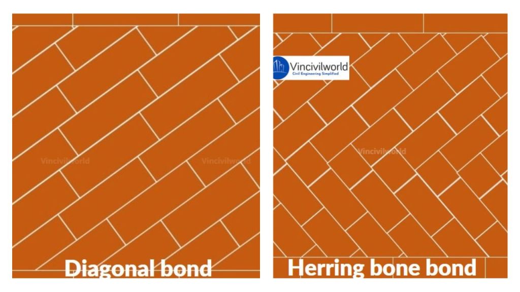
Raking bond
Raking bond is a type of brick bond in which the bricks are laid at angles. In this case, bricks are placed at an inclination to the direction of walls. Generally, it is commonly applicable for thick walls. Normally laid between two stretcher courses. There are two types of Raking bonds
Diagonal bonds
Herringbone bonds
Diagonal bonds
In diagonal bonds, bricks are laid inclined, the angle of inclination should be in such a way that there is a minimum breaking of bricks. These dioganal bonds are mostly applicable for walls of two to four brick thickness. Similarly, the triangular-shaped bricks are used at the corners.
Racking bond – Brick bond types
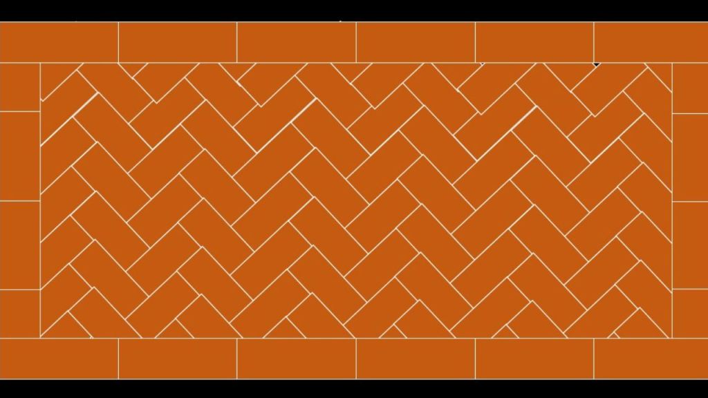
Herringbone bonds
This type of bond is applicable in thick walls. The bricks are laid at an angle of 45 degrees from the centre in two directions. Mostly used in paving.
Zigzag Bond
In this type of bond, bricks are laid in a zig-zag manner. It is similar to the herringbone bond. Since Zig zag bond has an aesthetic appearance it is used in ornamental panels in brick flooring.
Zigzag Bond
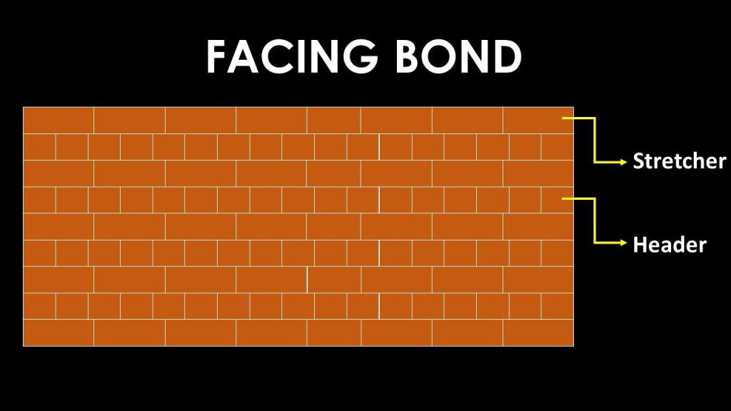
Facing Brick Bonds
In facing bond bricks are used of different thicknesses. It has an alternative course of stretcher and header. The load distribution is not uniform in this type of bonding. So it is not suitable for the construction of masonry walls.
Facing brick bond
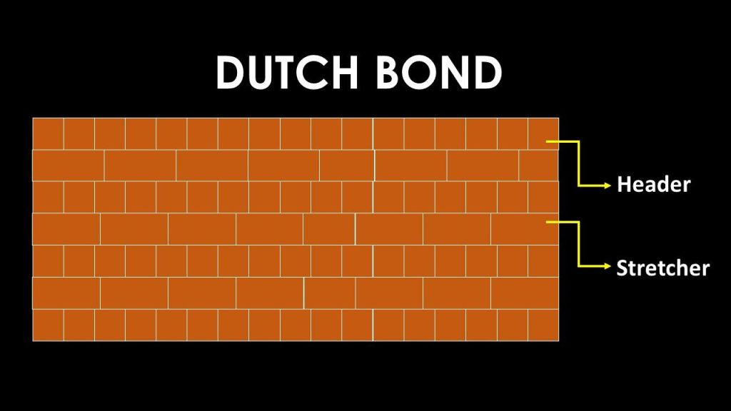
Dutch Bond
It is a type of English bond. The specific pattern of laying bricks for building a wall is known as English and Dutch bonds. The primary distinction is that English Bond is a bond used in brickwork that consists of alternate courses of stretchers and headers. Dutch bond – made by alternating headers and stretchers in a single course.
Rat trap bond
Another name of the rat trap bond is the Chinese bond. In this type of bond, the bricks are placed in such a way that a void is formed between them. These voids act as thermal insulators. Thus provides good thermal efficiency. It also reduces the number of bricks and the amount of mortar. Construction of rat trap bonds requires skilled labors.
Rat trap bond
Key Takeaways
Bonds in brick masonry refer to the systematic arrangement of bricks, designed to ensure not only structural strength and durability but also visual appeal. These bonds play a crucial role in construction, with different types serving specific functional and aesthetic purposes. Among the most common are stretcher bond, header bond, English bond, Flemish bond, and herringbone bond. Each of these varies in brick placement, pattern, and suitability for different wall thicknesses. For instance, the English bond, with its alternating courses of headers and stretchers, offers superior strength. Meanwhile, the Flemish bond strikes a balance between strength and decorative appeal. By minimizing continuous vertical joints, proper bonding improves wall stability and evenly distributes loads. Therefore, understanding these bonds is vital for architects, builders, and masons when selecting the most suitable pattern for structural and design needs.
Conclusion
Brick masonry bonds are fundamental to constructing strong, durable, and visually pleasing structures. The choice of bond affects not only the structural integrity of walls but also their appearance and cost. For load-bearing walls, stronger bonds like English or Flemish are preferred, while stretcher bonds are suitable for partition walls. Correct bonding plays a vital role in minimizing joint alignment and efficiently distributing loads across the wall. Consequently, this enhances the structural integrity of the masonry.
Since each bond type offers distinct advantages, it becomes crucial to make selections based on both functional requirements and architectural aesthetics. Moreover, mastering the use of brick bonds leads to quality workmanship, ensuring not only structural reliability but also greater design flexibility. In addition, choosing the right bond supports construction efficiency and durability.
As a core principle in masonry, understanding the purpose and application of different bonds significantly improves overall construction quality. Ultimately, this knowledge contributes to the long-term performance and sustainability of brick structures across residential, commercial, and infrastructural projects.
Bitumen for roads is an important topic to understand when it comes to road construction. Bitumen is used in road construction because of the wide range of features and advantages it possesses over other pavement construction materials. The significance of bitumen in the construction of roads will be demonstrated in this article. In addition, we shall see bitumen road layers, various bituminous materials, cutback bitumen, bitumen grade, and bitumen properties.
Generally, tar is made by heating coal inside a chemical apparatus. Most tar is produced from coal as a byproduct of coke production, but it can also be produced from petroleum, peat or wood.
Bitumen for roads
The major steps in tar manufacturing are,
Coal undergoes carbonation and produces crude tar
Crude tar undergoes distillation/ refining and produces a residue
The residue blends with distilled oil fraction and produces tar
Desirable properties of bitumen- an important topic in bitumen for roads
The desirable properties of bitumen are,
Properties of Bitumen
Viscosity of bitumen during mixing and compaction is adequate
Bituminous material should not highly temperature and susceptible
In presence of water the bitumen should not strip off from aggregate
The adhesive property of bitumen binds together all the components without bringing about any positive or negative changes in their properties
Bitumen is insoluble in water and can serve as an effective sealant
Due to versatility property of Bitumen it is relatively easy to use it in many applications because of its thermoplastic property
Bitumen play a vital role in distributing the traffic loads on the pavement to the layers beneath
Bitumen for roads – Types of Bituminous materials
Okay. So, what are the types of bituminous materials that are used in flexible pavement construction? Below is the list for you.
Paving grade material
Modified bituminous binder
Cutback bitumen
Bitumen emulsion
Among the list, cutback bitumen is the major. Let me tell you more details about cutback bitumen.
Cutback bitumen
Cutback bitumen is the bitumen the viscosity of which is reduced by a volatile diluent. It is used in low-temperature mixing.
Three types of cutback bitumen are available
Rapid curing
Medium curing
Slow curing
The diluent while mixing varies with the type of cutback bitumen.
Type of cutback bitumen
Diluent
Rapid curing
Nafthal, gasoline
Medium curing
Carosine or diesel oil
Slow curing
High boiling point gas oil
Type of cutback bitumen and suitable diluent
Bituminous emulsion
A bitumen emulsion is a liquid product in which a substantial amount of bitumen suspended in a finely divided condition in an aqueous medium and stabilized by means of one or more suitable material
To determine the grade of bitumen, penetration test is conducted. The results are expressed in 1/10 mm. When penetration value is represented as 80/1000, it is called grading of bitumen.
The old method of grading is viscosity test. Two viscosities kinematic and absolute and penetration value by penetration test results are collected. Based on this, bitumen is graded. The tables shows the grade of bitumen and values of viscosity in accordance with penetration.
Grade of bitumen
Absolute viscosity
Kinematic viscosity
Penetration
VG 10
800
250
80- 100
VG 20
1000
300
60- 80
VG 30
2400
350
50- 70
VG 40
3200
400
40- 60
Grade of bitumen and viscosity
Let me tell you the application of each of the grade of bitumen now.
VG- 10- Used in spray application since viscosity is very less
VG- 20- Used in cold area
VG- 30- Commonly used in India
VG- 40- High grade bitumen used in high traffic areas
Okay. So, lets’ learn about the bituminous layers.
The bitumen road layers come in the surface layer shown in the figure above. The figure below shows that. Bituminous mix consists of aggregate and binder. Aggregate consists of coarse aggregate, fine aggregate and filler less than 0.075mm.
Bituminous concrete consists of aggregate and bitumen.
Thickness of base course depends on grading of aggregate
Dense graded aggregates are provided in base course. That is the permeability will be very less
Number of voids should be very less
Dense bituminous macadam should be given as a binder course
So, the trip is over. Hope the time you spend for reading about the bitumen for road was worth it.
Cutback bitumen (MC30, RC70) is used where quick curing is needed.
Bitumen ensures strong bonding between road layers and improves lifespan.
Engineers select bitumen grades based on climate and traffic needs.
Proper bitumen selection enhances pavement performance and sustainability.
Conclusion
Bitumen for roads plays a critical role in the construction and performance of modern pavements. Its unique properties—such as waterproofing, adhesion, flexibility, and resistance to traffic loads—make it a preferred material for road engineers worldwide. Engineers employ various types and grades of bitumen for applications ranging from base layers to surface sealing, based on project requirements and environmental conditions. They use penetration and viscosity grades for high-traffic areas, while they choose emulsions and cutbacks for lower-volume roads and cooler climates. Each bitumen type serves a specific purpose in road layers like prime coats, binder courses, and tack coats. Ultimately, the correct selection and application of bitumen ensure a durable, cost-effective, and long-lasting road infrastructure.
Bitumen types for road layers are a vital topic to comprehend when it comes to road construction. Bitumen is preferred for flexible pavements in road construction because it has many advantages over other pavement construction materials. This article will demonstrate the importance of bitumen in road construction and the types of bitumen for road construction. Furthermore, bitumen emulsion types for road layers, different bituminous materials, cutback bitumen, bitumen grade, and bitumen attributes will be highlighted in this article.
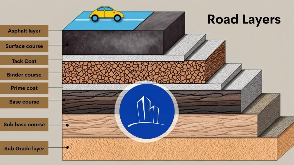
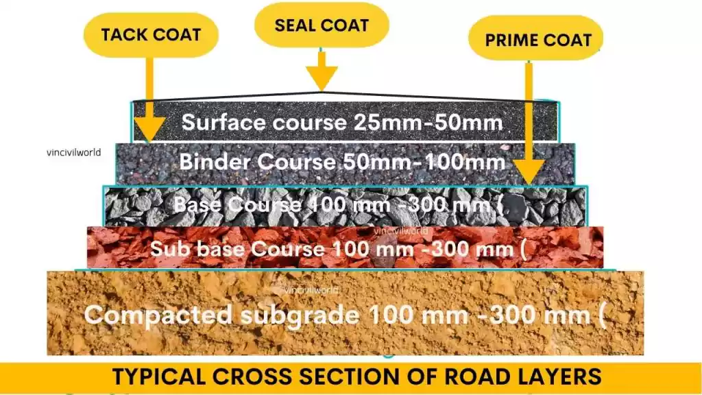
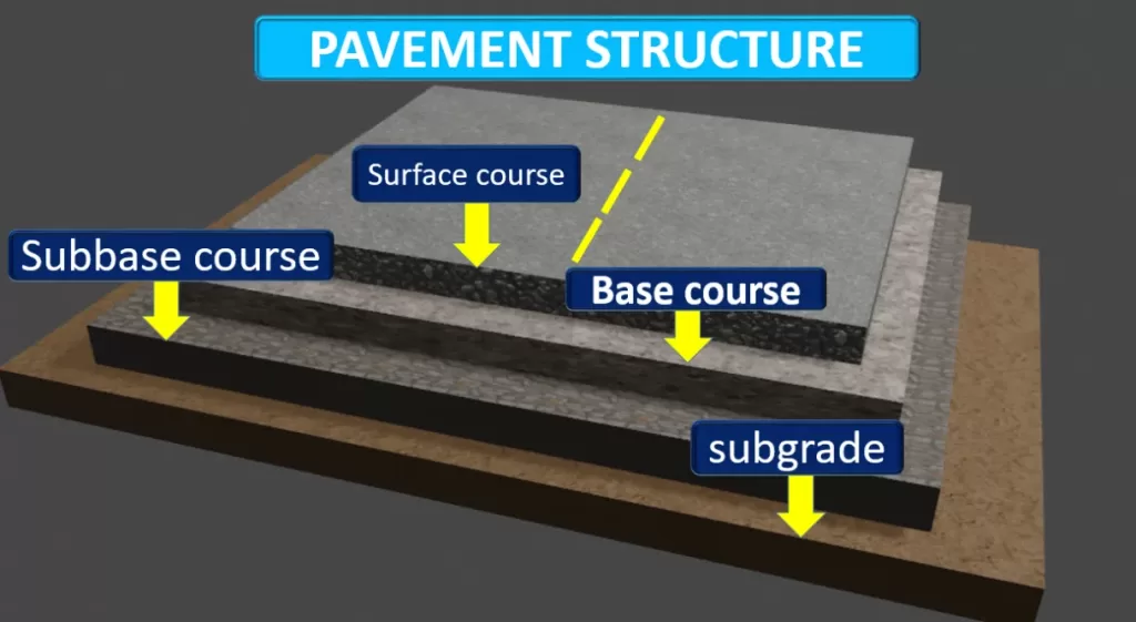
The flexible pavement structure consists of the following layers:
Tack Coat
Binder Course
Prime Coat
Base Course
Sub-base Course
Subgrade Course
Bitumen types for road layers
Keep in mind that the primary component of the road is not protective asphalt. Protective asphalt is deployed to safeguard the road’s surface. Every layer mentioned above uses a different type of bitumen. We will illustrate what types of bitumen are used in each of these layers.
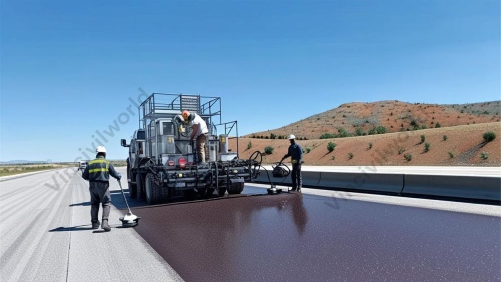
Tack Coat – Bitumen types for road layers
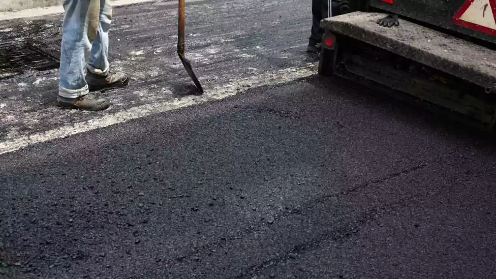
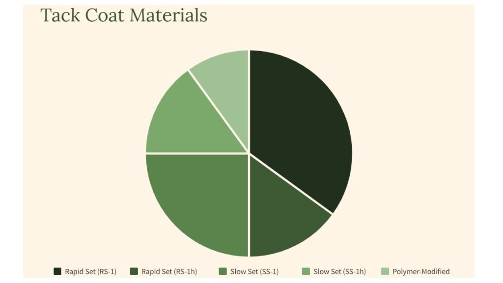
The application of coatings is a critical phase in the construction of asphalt roadways. Generally, a tack coat is a thin layer of asphalt emulsion or liquid bitumen used in between layers of hot mix asphalt to prevent slippage. Mostly, MC30 cutback bitumen, CRS-1, and CRS-2 emulsion bitumen are utilised in a tack coat layer of bitumen. The lower layer is sealed by the presence of a tack coat, which also increases the strength of both asphalt layers.
Tack coat materials
MC-30 is a medium-curing cutback bitumen that is ideal for cold climates. Basically, asphalt emulsions are the most often used tack coat materials. However, the most widely used slow-setting emulsions are SS-1, SS-1h, CSS-1, and CSS-1h (1). The usage of rapid-setting asphalt emulsions like RS-1, RS-2, CRS-1, and CRS-2 for tack coats is also on the rise.
The base course and the surface course are separated by the binder course. Generally, a binder course is used to keep the road surface from moving. Because the binder course is made out of coarse aggregates, less bitumen is utilised in the manufacture of this asphalt. In the hot asphalt of the binder course, various grades of pure bitumen can be utilised. The various grades of pure bitumen used in binder courses are listed in the table below.
Penetration Grade
Viscosity Grade
30/40
VG 10
40/50
VG 20
60/70
VG 30
80/100
VG 40
120/150
Bitumen types for road layers
Prime Coat – Bitumen types for road layers
A prime coat is a coating that is applied directly to the base layer. The primary objective of utilising the prime coat is to improve the bond between the base layer and the asphalt mix layer. It also fills in the voids. A priming coat might aid in sealing the base layer. The bitumen in prime coatings is either CSS or CMS.
Prime coats aid in reducing dust while protecting the granular base’s integrity throughout construction. In the event of a foundation that will be covered with a thin hot mix layer or a chip seal for a low-volume roadway, priming enables a good bond between the seal and the underlying surface, which might otherwise delaminate.
A primary coat is primarily responsible for safeguarding the substrate of a construction project before applying additional layers. They can also function as a binder with secondary and tertiary compounds in the preparation of asphalt, improving the adherence of the layers. Following the prime coat, a tack coat is applied to provide an adhesive bond between the tack coat and the subsequent layer of coating. For asphalt prime coat systems, the tack coat is one of the most vital parts of the process, as it connects the subsequent layers and forms the base of those layers’ strength.
Base Course
The base course is placed directly on top of the subbase course. This layer has a higher permeability than the sub-base layer because it is composed primarily of coarse aggregates. Basically, the base course, which is the first layer in direct contact with traffic, moves the weights from the upper layers to the sub-base course. Different base courses used in pavement include sand or stone base, macadam base, and bitumen base.
road-layers-of-flexible-pavement
Bitumen types for road layers
Sub Base Course
The first layer of flexible pavement constructed on the ground is the sub-base course. This layer is typically composed of river sand, an alluvial cone, and broken rock. Bitumen and cement can be used to stabilise the sub-base soil.
Sub Grade
It is the surface upon which further pavement layers such as the sub-base course, base course, and asphalt layers are placed. The subgrade absorbs any load tension or weight that is transferred from the top levels. A good subgrade should be able to support weights for a considerable amount of time without deforming.
Protective Asphalt
Generally, Protective asphalts are used to seal the road surface and improve the asphalt temporarily. However, It should be noted that asphalt sealing can cause the asphalt to become more slippery. Pure bitumen with low humidity and soluble bitumen are both utilised in protective asphalt. Because of its quickness and ease of installation, protective asphalt is more cost-effective than hot asphalt. There are various varieties of protective asphalts, some of which are listed below:
Seal coat
Slurry seal
Chip seal
Micro-surfacing
Fog seal
Seal coat
A seal coat is used to provide a long-lasting surface texture and to keep the surface waterproof. However, this kind of protective asphalt can be made using a variety of emulsion bitumen types, including CSS-1, SS-1h, SS-l, and CSS-1h.
Seal coat : Bitumen layer
Slurry Seal
Generally, a slurry seal is used to lessen the harm done by bitumen oxidation. In the slurry seal, emulsion bitumen’s SS-1, SS-h1, CSS-1h, and CQS-1h are used. A slurry seal is appropriate for pavements with little to moderate damage, such as narrow cracks. However, it is not appropriate for severe damage such as holes.
Chip Seal
A chip seal is a thin protective surface that is applied to a pavement or subgrade. Water cannot easily seep through the base layer due to the chip seal. This layer also prevents freezing in areas where the temperature is below zero. Adding this layer improves the road’s reflectiveness for night-time driving. A rapid-setting emulsion containing a CRS-2, RS-2, HFRS-2, and PMB is the best type of bitumen for chip sealing.
Micro Surfacing
Micro-surfacing aids in the sealing of cracks and the protection of existing bituminous layers against surface voids and minor ruts. Among the benefits of adopting this layer are environmental compatibility, cost-effectiveness, and fast construction time. PMB bitumen’s such as PMCQS-1h, PMQS-1h, and CQS-1P are suited for it.
Micro surfacing
Fog Seal
A fog seal is intended to neutralize the oxidation process that occurs over time. This layer protects the pavement surface by leaving a hard layer. This layer employs emulsion bitumen such as SS-1, SS-1h, CSS-1, or CSS-1h.
Key takeaways
Bitumen is crucial for flexible pavements in road construction.
Each pavement layer requires a different type of bitumen.
MC-30, CRS-1, and CRS-2 are used in tack coats for bonding layers.
Binder courses use penetration and viscosity grade bitumen like VG10–VG40.
Prime coats enhance adhesion between base and asphalt layers using CSS or CMS.
Base courses distribute traffic loads and can include macadam or bituminous bases.
Sub-base and subgrade layers form foundational support, often stabilized with bitumen or cement.
Protective asphalts like seal coats and micro-surfacing preserve road surfaces.
Emulsion types vary based on application needs.
PMB enhances performance in protective layers.
Conclusion
Bitumen types for road layers play a vital role in constructing durable and long-lasting roads. Each layer in flexible pavement—from subgrade to surface—demands a specific bitumen type tailored to its function and environmental conditions. Emulsion bitumen’s like CRS, SS, and CSS grades ensure proper bonding and waterproofing. Meanwhile, advanced types such as PMB (Polymer Modified Bitumen) provide improved durability and performance for protective layers like micro-surfacing and chip seals. Understanding the right bitumen type for each layer not only boosts road strength but also extends its lifespan. By choosing appropriate materials and applications, engineers can construct efficient road systems that perform reliably under varying load and weather conditions.
Radiography test is a non-destructive testing (NDT) method. It uses X-rays or gamma rays to examine the internal structure of materials. This technique is essential for detecting hidden flaws without causing damage, ensuring the integrity and safety of components. Radiography test is widely applied in industries such as manufacturing, construction, and aerospace to inspect welding, castings, and structural components. The process involves placing the test object between a radiation source and a detector. An image is captured that reveals internal features. It highlights potential defects. Advancements in digital radiography have enhanced the efficiency and accuracy of these inspections. This process has solidified Radiographic testing as a cornerstone in quality assurance and safety protocols across various sectors.
In this article, we will delve into the principles, techniques, and applications of Radiography test. We’ll explore its significance in non-destructive evaluation, the equipment utilized, and the step-by-step process involved. Additionally, we’ll emphasis on the advantages, limitations, safety considerations, and recent advancements in the field. This comprehensive guide aims to offer a thorough understanding of radiography test and its pivotal role across various industries.
Radiography test is a non-destructive testing (NDT) method. It utilizes X-rays or gamma rays to examine the internal structure of materials. The fundamental principle involves directing radiation through a test object. The radiation is projected onto a detector, like photographic film or a digital sensor. Variations in material density and thickness affect the absorption of radiation. Denser areas absorb more, resulting in lighter regions on the radiography. Meanwhile, less dense areas are darker. This contrast enables the detection of internal flaws like cracks, voids, or inclusions. Radiography test is widely applied across industries. These include aerospace, construction, and manufacturing. This ensures the integrity and reliability of critical components.
RT
In radiography tests, X-rays and gamma rays interact with materials primarily through three mechanisms:
Photoelectric Absorption: Low-energy photons are absorbed by tightly bound electrons, ejecting them from atoms. This effect is more pronounced in materials with higher atomic numbers.
Compton Scattering: Moderate-energy photons collide with loosely bound electrons, resulting in photon deflection and energy loss. This process contributes to image contrast but can also cause image blurring.
Pair Production: High-energy photons (above 1.022 MeV) can transform into an electron-positron pair near a nucleus. This phenomenon becomes significant at higher photon energies.
These interactions cause attenuation of the radiation beam. The degree of attenuation depends on the material’s thickness, density, and atomic number. By analyzing the transmitted radiation, Radiographic testing reveals internal structures and potential defects within the material.
Types of Radiography Tests
Radiography test (RT) is a non-destructive testing method. It employs X-rays or gamma rays to inspect the internal structure of materials. This ensures the integrity and reliability of components across various industries.
Film Radiography
Digital Radiography (DR)
Computed Radiography (CR)
Real-Time Radiography (RTR)
Computed Tomography (CT)
Each of these radiography testing techniques offers unique advantages. The choice among them depends on specific inspection requirements. It also relies on material types and desired image clarity.
Film Radiography test
Film radiography is a traditional non-destructive testing (NDT) method. It effectively utilizes X-rays or gamma rays. These rays inspect the internal integrity of materials and components. In this process, a Radiographic film is placed behind the test object, and radiation is directed through the material. As a result, variations in material density and thickness affect the radiation’s absorption, creating a latent image on the film. Once the chemical processing is complete, this film reveals an image highlighting internal features and potential defects like cracks, voids, or inclusions. Due to its precision, film radiography is renowned for its high-resolution imaging capabilities, making it a reliable choice for detecting even the smallest irregularities. This makes it a preferred choice in industries like aerospace, construction, and manufacturing. Despite advancements in digital radiography, film radiography remains valued for its ability to produce detailed images essential for critical inspections.
Radiography test
Digital Radiography test
Digital Radiography (DR) is an advanced non-destructive testing (NDT) method. It employs digital detectors to capture X-ray or gamma-ray images of a material’s internal structure. Unlike traditional film radiography, DR offers immediate image acquisition and processing, enhancing inspection efficiency and reducing exposure times. This technique provides high-resolution images, facilitating the detection of defects like cracks, voids, and inclusions. Digital Radiography systems also enable easy storage, retrieval, and sharing of digital images, improving workflow and collaboration among inspection teams. Additionally, the Digital Radiography test reduces the need for hazardous chemicals used in film processing. This ultimately promotes a safer and more environmentally friendly work environment. Moreover, its versatility and rapid results have made Digital Radiography testing a preferred choice in various industries, including aerospace, automotive, and oil and gas. In these fields, ensuring the integrity and reliability of critical components is absolutely essential.
Computed Radiography
Computed Radiography (CR) is a modern digital imaging technology that effectively replaces traditional film-based radiography by utilizing photostimulable phosphor (PSP) plates. These advanced plates capture X-ray images efficiently. In this process, the PSP plate is first exposed to X-rays, then stores the image as a latent energy pattern, ensuring accurate and detailed imaging. Subsequently, a laser scanner reads the plate. It releases the stored energy as light. This light is then converted into a digital image for analysis. Computed Radiography offers several advantages over conventional film radiography. These advantages include reduced exposure to radiation and elimination of chemical processing. CR also provides the ability to enhance and digitally archive images. This technology is widely used in medical diagnostics and industrial non-destructive testing, providing a cost-effective and efficient solution for capturing high-quality radiographic images.
Real-Time Radiography test (RTR)
Real-Time Radiography test (RTR) is a non-destructive testing (NDT) technique that enables immediate visualization of an object’s internal structure. X-rays or gamma rays are directed through the test object. They then reach a real-time detector, like a fluorescent screen or digital panel. RTR produces live images and allows for the dynamic observation of components. This immediacy facilitates the detection of defects like cracks, voids, or inclusions during ongoing operations. Real-Time Radiography test (RTR) is widely employed across industries including automotive, aerospace, and electronics. Real-time feedback is crucial in these fields to guarantee part integrity and safety.
Computed Tomography (CT)
Computed Tomography (CT) is an advanced imaging technique that effectively utilizes X-rays to generate detailed three-dimensional representations of an object’s internal and external structures. Unlike traditional methods, the Computed Tomography test captures multiple two-dimensional Radiographic images from various angles. Subsequently, this process reconstructs a comprehensive 3D model, which allows for a thorough examination without causing any damage to the specimen.
Due to its precision and reliability, this non-destructive testing (NDT) method is invaluable across various industries. It is used in aerospace, automotive, and manufacturing and enables precise detection of internal defects. This also allows measurement of complex geometries and verification of material integrity.
Visualizing internal features in high resolution enhances quality control processes. This capability also aids the development of safer and more reliable products. As technology advances, CT continues to evolve. It offers faster scanning times. It also provides improved image clarity. This further solidifies its role as a critical tool in modern NDT practices.
Equipment Used in Radiography Test
Radiographic testing (RT) employs various specialized equipment to inspect the internal structure of materials non-destructively. Essential equipment includes X-ray and gamma-ray sources, detectors, and imaging systems.
Key Equipment Used in Radiographic Testing
Radiation Sources:
X-ray Machines: Generate X-rays using X-ray tubes, commonly employed in medical and industrial applications.
Gamma-ray Sources: Utilize radioactive isotopes like Iridium-192 or Cobalt-60 for material penetration, especially in industrial settings.
Detectors:
Film Radiography: Traditional method using photographic film to capture images after exposure to radiation.
Digital Detectors: Include Computed Radiography (CR) systems with phosphor imaging plates and Digital Radiography (DR) systems with flat-panel detectors for immediate digital imaging.
Image Processing Systems:
Computed Tomography (CT) Scanners: Acquire multiple radiographic images from different angles to create detailed cross-sectional views.
Ancillary Equipment:
Radiation Shielding: Protective barriers and enclosures to safeguard operators from exposure.
Film Processors: Develop exposed films in traditional radiography.
Viewing Stations: Lightboxes or digital monitors for analyzing radiographic images.
The selection of equipment depends on the specific application, material type, and required inspection standards.
Applications of Radiography test
Radiography Testing (RT) is a crucial non-destructive testing (NDT) method widely used across various industries. Specifically, its main purpose is to assess the internal integrity of materials and components. By utilizing X-rays or gamma rays, RT provides detailed images that effectively reveal internal defects. As a result, this method ensures the safety and reliability of critical structures.
Radiography test for welding
Radiography Test is extensively used to evaluate weld quality in pipelines, pressure vessels, and structural components. It detects defects such as cracks, porosity, and incomplete fusion. Radiography test for welding confirms the weld quality.
Applications of radiography test
Casting Inspection
RT is employed to detect internal defects in metal castings. These defects include shrinkage cavities, gas porosity, and inclusions. This process ensures the structural integrity of cast components.
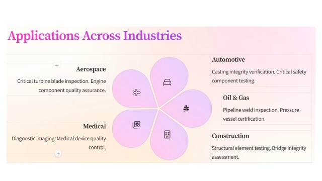
Aerospace Industry
It ensures the integrity of aircraft components, such as turbine blades and structural elements. It does this by identifying internal flaws that compromise safety.
Automotive Sector
Inspects welds, castings, and assemblies to detect defects affecting vehicle performance and safety.
Petrochemical Industry
Examines pipelines, storage tanks, and pressure vessels for corrosion, cracks, and other defects, preventing potential failures.
Manufacturing
Assesses castings, forgings, and other fabricated components to ensure they meet quality standards by detecting internal discontinuities.
Power Generation
Evaluates critical components in nuclear and conventional power plants. This includes reactor vessels and steam generators. These evaluations ensure structural integrity.
Radiography test
Construction
Checks concrete structures and welds in buildings and bridges for internal defects, ensuring structural safety and compliance with regulations.
Radiographic Testing provides a non-invasive means to detect internal flaws. It plays an essential role in maintaining the quality and safety of products. This ensures infrastructure safety across these sectors.
Advantages of Radiography test
Radiographic Testing (RT) is a non-destructive evaluation method. It uses X-rays or gamma rays. These rays inspect the internal structure of materials and components. This technique offers several notable advantages
High accuracy
RT provides precise detection of internal defects. These include cracks, voids, and inclusions. This precision ensures the integrity of critical components. The radiation source size significantly affects Radiographic testing accuracy. A larger source provides more uniform exposure, creating clearer and more accurate images.
Versatility
RT inspects a wide range of materials, including metals, plastics, and composites. Various industries, such as aerospace, manufacturing, and construction, utilize it.
Minimal Material Limitations
RT can be applied to most types of materials. This makes it a versatile choice for inspecting diverse components.
Volumetric Examination
Considered a universal approach to volumetric inspection, RT examines the internal integrity of objects, providing a comprehensive assessment of their condition.
Permanent Inspection Records
RT produces lasting records of inspections, which can be reviewed and referenced for future evaluations, aiding in quality control and compliance documentation.
Sensitivity to Thickness and Density Variations
RT can detect small changes in thickness and density, down to about 1%, along the path of the X-ray beam, allowing for precise identification of defects.
By providing detailed insights into the internal condition of materials without causing damage, Radiographic Testing plays a crucial role in ensuring the safety, reliability, and quality of products and structures across multiple sectors.
Limitations and Safety Considerations of Radiography test
Radiographic Testing (RT) is a valuable non-destructive testing method, but it has several limitations and safety considerations:
Safety Concerns
The use of ionizing radiation poses potential health hazards to personnel. Strict safety measures, including shielding and monitoring, are essential to minimize risks.
High Operational Costs
RT is relatively expensive. This is due to the cost of equipment and materials. It also requires highly trained operators.
Accessibility Requirements
Both sides of the object must be accessible for effective inspection, which can be challenging for certain components.
Complex Geometry Challenges
Specimens with complex shapes may be difficult to inspect accurately using RT.
Detection Limitations
Small, isolated defects less than 2% of the total thickness may not be detected, and defects not aligned with the radiation beam can be challenging to identify.
Health Risks
Exposure to ionizing radiation can lead to severe health issues, including radiation burns and increased cancer risk.
Environmental Impact
Improper handling and disposal of radioactive materials can adversely affect the environment.
Regulatory Compliance
Strict adherence to radiation safety regulations and guidelines is necessary to protect workers and the public.
Addressing these limitations and safety considerations is crucial for the effective and safe application of Radiographic Testing.
Recent Advances in Radiography Test
Radiographic Testing (RT) has experienced significant advancements, enhancing its accuracy, efficiency, and applicability across various industries. Key developments include:
1. Artificial Intelligence (AI) Integration: AI-powered imaging has revolutionized defect detection and analysis in RT. Advanced algorithms, like 3D Generative Adversarial Networks (GANs), synthesize volumetric computed tomography (CT) data. They help multi-angle defect training. This enables real-time augmentation and improves accuracy.
2. Digital Radiography (DR): The transition from traditional film-based systems to DR has led to faster image acquisition. It has also enhanced image quality and reduced radiation exposure. High-resolution flat-panel detectors and direct conversion sensors further improve diagnostic precision.
3. In-Line Computed Tomography (CT): Integrating CT systems directly into production lines allows for real-time inspection and quality control. AI-driven reductions in scan duration make it easier to detect minute defects. These include 30 µm voids in additive-manufactured parts or cracks in turbine blades.
4. Flexible X-Ray Detectors: Innovations like bendable materials capable of wrapping around complex structures have emerged. These flexible detectors enhance inspections in confined or awkward spaces. They are particularly useful in industries like aeronautics. They offer a versatile option to rigid, flat scanners.
5. Enhanced Software Platforms: Modern software developments provide intuitive touch interfaces. For example, the Rhythm RT platform simplifies operation and increases efficiency. These platforms require minimal operator training and maximize the capabilities of portable Radiographic imaging systems.
6. High-Brightness Photon Sources: High-brightness MeV-photon sources are developed based on laser-wake-field accelerators. This development has opened new possibilities for high-resolution radiography of dense, thick objects. Spatial resolutions better than 2.5 line pairs per millimeter at energies in the MeV range have been demonstrated.
These advancements collectively contribute to more precise, efficient, and versatile radiographic testing, ensuring higher quality standards across various applications.
Conclusion
Radiographic Testing (RT) is a cornerstone of non-destructive testing, as it employs X-rays and gamma rays to effectively reveal internal structures. Moreover, this method detects flaws in materials without causing any damage. Due to its reliability, its applications span various industries, including aerospace, automotive, construction, and manufacturing. Ultimately, this ensures the integrity and safety of critical components and structures.
Recent advancements have significantly enhanced RT’s capabilities. The integration of Artificial Intelligence (AI) has revolutionized image analysis, enabling faster and more accurate defect detection. Digital Radiography (DR) has replaced traditional film, offering immediate results and improved image quality. In-line Computed Tomography (CT) systems now facilitate real-time inspections within production lines, boosting efficiency and precision.
Looking ahead, the future of RT is poised for further innovation. The development of portable neutron sources and flexible X-ray detectors promises greater versatility in inspecting complex structures. Enhanced software platforms are streamlining operations, reducing the need for extensive operator training. Additionally, the emergence of high-brightness photon sources is enabling high-resolution imaging of dense objects.
As these technologies evolve, RT will continue to play a pivotal role in quality assurance and safety across industries. Embracing these emerging trends is crucial. Professionals must maintain high standards. They need to adapt to the dynamic landscape of non-destructive testing.
Key takeaways
Radiography Test (RT) is a pivotal non-destructive evaluation method that effectively utilizes X-rays or gamma rays to inspect the internal structure of materials. By doing so, this process ensures the integrity of components across various industries. Some key takeaways include:
Detection of Internal Defects: RT effectively identifies hidden flaws such as cracks, voids, and inclusions, which are not visible on the surface, thereby preventing potential failures. Radiography test for welding can find out weld quality.
Versatile Applications: This technique is widely employed in sectors like aerospace, construction, and manufacturing to assess welds, castings, and structural components.
Permanent Inspection Records: RT provides lasting documentation of inspections, facilitating future reference and quality assurance.
Safety Considerations: The use of ionizing radiation necessitates stringent safety protocols to protect personnel and the environment.
Technological Advancements: Innovations such as digital radiography and computed tomography have enhanced image quality, reduced exposure times, and improved defect detection capabilities.
By understanding these aspects, industries can effectively leverage Radiographic Testing to maintain high-quality standards and ensure operational safety.