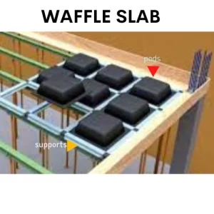
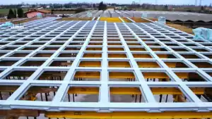
Ribbed concrete slabs, also known as waffle slabs, are a type of reinforced concrete slab characterized by a grid-like pattern on the underside. This grid resembles the pockets of a waffle. It consists of ribs running in two perpendicular directions. These ribs provide enhanced strength and stability. Ribbed concrete slabs, or two-way joist slabs, are highly effective for spans over 40 feet (12 meters). They offer superior load-bearing capacity compared to other slab types, such as flat slabs, flat slabs with drop panels, two-way slabs, one-way slabs, and one-way joist slabs.
Though ribbed concrete slabs can be more expensive than other slab systems, they offer increased rigidity and stability, making them ideal for both ceiling and floor applications. These slabs are essential structural components in buildings, providing a flat surface and assisting in the transfer of loads. In this article, we will discuss the construction process, advantages, and disadvantages of ribbed concrete slabs and waffle slabs.
A ribbed concrete slab, also called a waffle slab or two-way joist slab, is ideal for industrial and commercial buildings. It has a flat top and grids on the underside. Ribbed concrete slabs are stronger than flat slabs, making them perfect for longer spans. They handle both distributed and point vertical loads.
Ribbed concrete slab or waffle slab
It enables both distributed and point vertical actions. The bottom layer of concrete reinforcement in ribbed concrete slab/waffle slabs is removed. Instead, concrete ribs run in two orthogonal directions. Additionally, the rib depth should range from 135mm to 235mm. Because the overall depth of the floor increases as the depth of the ribs does. The structure’s lateral loading is impacted by this.
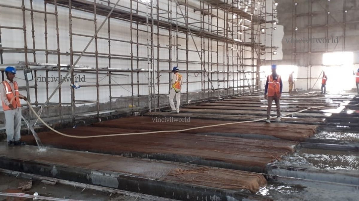
The waffle slabs need only 70% of concrete and 80% of steel from the concrete and steel used for the construction of the raft slab. The construction stages of the waffle slab include the following
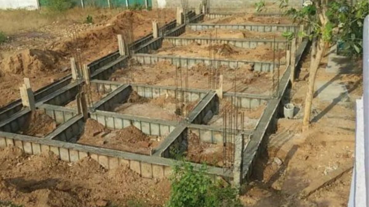
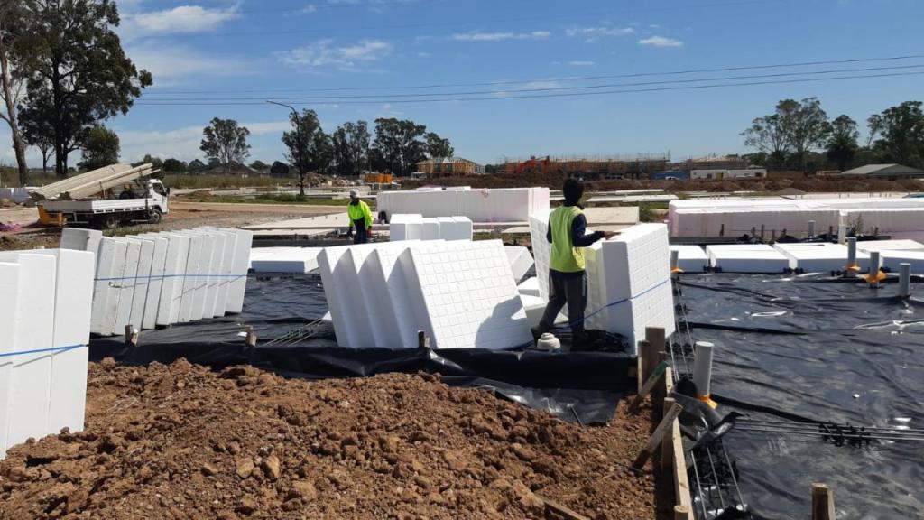
The first step is to create the forms
Place the formwork components in place.
Position your waffle pods or moulds on the shuttering. Generally, the pods are typically constructed of plastic, and they come in a variety of sizes and shapes. The size of the pod is determined by the requirements and span length. A significant number of pods are necessary for greater spans. Accordingly, the same size pods should be used for the entire slab.
Ribbed concrete slab or waffle slab
Place the support components horizontally and vertically according to the connectors.
Lay out the waffle pods and spacer within the formwork in a grid pattern beginning at one corner, following the instructions in the design.
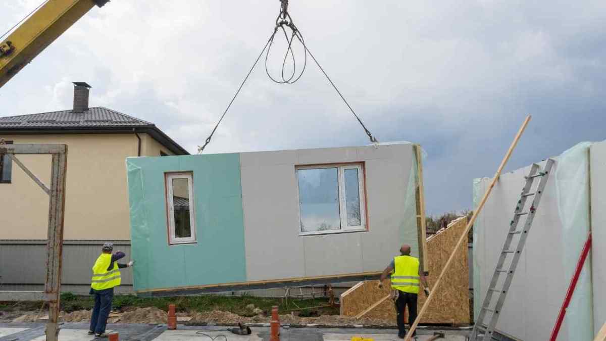
Using this technique, the casting of the slab panel is done elsewhere, and it is then placed, connected, and reinforced with concrete.
Prefabricated
In this procedure, reinforcement is built into the slab panels using prefabricated steel bars. Slabs are manufactured elsewhere and brought to the location to be erected.
Advantages of Waffle slab
It is suitable for large-span structures and can be achieved with less concrete and rebar than similar conventional slabs
They require only a fewer number of columns.
It possesses a higher load-carrying capacity
It has higher structural stability
They have a good aesthetic appearance.
Waffle slabs are suitable for roof slabs and floor slabs.
Waffle slabs have high vibration control capacity
The construction of this slab can be done faster and easier.
They are light weighted
They require low construction costs, Hence they are economical when compared to other conventional slabs of the same span
It requires only less amount concrete and can be reinforced with mesh or rebars.
Disadvantages of Waffle slab
Requires Expensive formwork
Requires skilled workmen and supervision for the construction of waffle slabs.
Higher maintenance cost
The increase in the depth of ribs leads to an increase in the floor height.
This type of slab is not suitable for windy and slope areas.
Key Takeaways
Ribbed concrete slabs, also known as waffle slabs, are reinforced concrete systems with a grid-like pattern on the underside. They offer enhanced strength, making them ideal for longer spans, and are highly effective in handling both distributed and point vertical loads. These slabs are suited for industrial and commercial buildings and are made using a process that involves creating forms, placing waffle pods, reinforcing with steel, and pouring concrete. Waffle slabs have advantages such as higher load-carrying capacity, stability, and aesthetic appeal. However, they require expensive formwork, skilled labor, and can incur higher maintenance costs.
Conclusion
Ribbed concrete slabs or waffle slabs are a versatile solution for large-span structures. They are stronger and more stable than conventional slabs, making them ideal for industrial, commercial, and residential buildings. Their efficient use of concrete and steel reduces material costs compared to other slab systems. However, the construction process requires skilled labor and specialized equipment, which can increase upfront costs. Despite these challenges, the long-term benefits of waffle slabs, such as reduced need for columns, higher structural stability, and aesthetic appeal, make them a valuable choice in modern construction. Understanding the advantages and disadvantages is crucial when considering them for specific projects.
Pond ash is a by-product of coal-fired power plants. It has several applications in civil engineering mainly in the construction sector. It is collected in an ash pond, where fly ash and bottom ash are stored after mixing with water. Pond ash has a range of applications in construction and infrastructure projects. It is widely used in brick manufacturing, road construction, and soil stabilization. Understanding what is pond ash is essential for effective fly ash pond management. This material is valued for its cost-effectiveness and ability to replace traditional resources like sand. Moreover, proper utilization of pond ash minimizes environmental hazards. By integrating sustainable practices, industries can improve ash pond management and reduce waste. Overall, pond ash plays a significant role in promoting eco-friendly and economical solutions in construction. In this blog, we will go through the basic details, properties, applications and limitations.
Pond ash is a by-product of coal-based power plants, primarily stored in an fly ash pond. It is a mix of fly ash and furnace bottom ash, deposited with water in designated areas.
What is pond ash? It is a material with properties that make it valuable for specific applications. While it lacks pozzolanic properties, its grain size distribution resembles sand. Therefore, pond ash can effectively substitute sand in construction projects.
Fly ash pond near power plant
Proper ash pond management is crucial for environmental safety and efficient resource utilization. Using pond ash in projects like road construction and soil stabilization reduces the need for natural materials. Moreover, it helps minimize waste and pollution from power plants. Industries are increasingly recognizing the significance of ash pond management to achieve sustainability goals. Overall, pond ash presents an eco-friendly solution for reducing environmental impact while offering practical benefits.
Furnace bottom ash (FBA) is a waste material, it generally has no pozzolanic property, and hence it cannot be utilised as a cement substitution material like fly ash.
On the other hand, its grain size distribution is like that of sand(CA)
So it can be utilised as a sand substitution material.
Pond ash is a waste product from coal-based power plants.
Ash pond is a pond developed in the power plant area to store ash.
Now, you know the basics. In the section, I will show you the importance of pond ash.
Why we should use pond ash?
Pond ash, a by-product of coal-fired power plants, offers a sustainable solution for construction needs while addressing environmental challenges caused by its accumulation near power plants. We are listing out some of the reasons to use pond ash.
Increasing Demand for Concrete
Concrete is one of the most important materials in building construction and other infrastructure works. By 2050, global concrete demand is projected to reach 7.5 billion m³ annually. Using pond ash can reduce reliance on natural aggregates.
Transportation of pond ash
Depletion of Natural Resources
At least three-quarters of the total volume of concrete consists of coarse and fine aggregates. River sand, a key component in concrete, is rapidly depleting. Pond ash can replace a percentage of sand in concrete effectively.
Abundant Availability
The power required for the country is rapidly increasing.In India, coal-fired power plants burn 407 million tons of coal annually, producing 131 million tons of coal ash. About 15–20% of this is bottom ash, offering significant potential for utilization.
Environmental Benefits
Accumulation of pond ash near thermal plants poses environmental risks. Its use in construction promotes effective ash pond management and reduces environmental threats.
Practical Suitability
Pond ash has fine particles (<4.75 mm) that make it a suitable substitute for fine aggregates in concrete without compromising strength or durability. It is found that it is possible to replace some per cent of sand by pond ash as fine aggregate in concrete without compromising on strength and durability.
Incorporating pond ash in construction is a sustainable step toward reducing waste and preserving natural resources.
Workability of Pond Ash Concrete
The workability of pond ash concrete (PAC) generally decreases as the percentage of fine aggregate replacement with pond ash increases. This reduction is primarily due to the specific surface effect of pond ash and its higher water absorption capacity. However, with proper combined grading techniques and the use of suitable plasticizers, workability can be significantly restored.
In fact, PAC mixes exhibit better performance than conventional concrete mixes in some aspects. The enhanced cohesiveness of the mix reduces segregation and eliminates bleeding, leading to improved overall quality.
Moreover, the careful adjustment of mix proportions ensures the required workability without compromising the strength or durability of the concrete. This makes pond ash concrete a viable alternative for sustainable construction practices.
Next, we will explore the many benefits of using this material in construction applications.
Benefits of Pond Ash
Pond ash offers several advantages, making it a valuable material in construction:
Economical Concrete: Utilizing pond ash reduces the overall cost of concrete production.
Effective Waste Management: It helps manage the waste generated by coal-based thermal power plants efficiently.
Reduced Construction Costs: By replacing fine aggregates like sand, pond ash lowers construction expenses.
Optimum Strength: Partial replacement of concrete with pond ash can achieve desired strength and durability.
Environmental Benefits: Using pond ash minimizes environmental degradation caused by its accumulation in ash ponds.
Incorporating pond ash aligns with sustainable construction practices, addressing economic, environmental, and waste management concerns effectively.
However, understanding its disadvantages is equally important to ensure balanced and practical applications.
Disadvantages of Pond Ash
While pond ash has benefits, it also presents several challenges:
Health Hazards: Fine particles from pond ash can cause severe respiratory problems.
Environmental Degradation: Ash pond areas lose vegetation and cannot be reclaimed for irrigation, impacting ecosystems.
Resource Depletion: Its use as a replacement for natural resources like sand can lead to further depletion of these materials.
Aesthetic Issues: Pond ash contributes to visual pollution in industrial areas.
Water Contamination: Collapsed fly ash pond bunds often pollute freshwater resources, creating long-term environmental issues.
Addressing these disadvantages requires efficient ash pond management and proper utilization practices to balance benefits and risks. Sustainable solutions are vital for minimizing its impact while leveraging its potential.
Key Takeaways
Definition and Origin:
Pond ash is a by-product of coal-fired power plants and stored in ash ponds for management.
Concrete Applications:
It can partially replace fine aggregates in concrete, reducing reliance on natural sand.
Workability and Mix Properties:
Workability decreases with higher replacement but can be restored using proper grading and plasticizers.
Reduces construction costs while maintaining strength and durability.
Minimizes environmental degradation caused by ash accumulation.
Disadvantages:
Causes respiratory health issues and environmental degradation.
Leads to visual pollution and depletion of natural resources.
Ash bund collapses can contaminate freshwater sources.
Sustainable Practices:
Proper ash pond management and innovative utilization methods are essential for balancing benefits and drawbacks.
Conclusion
Pond ash is a versatile material with potential in sustainable construction. The density of concrete decreases with an increase in pond ash replacement due to its low relative density. However, the compressive strength and flexural strength of concrete improve significantly up to 20% replacement with extended curing periods. Similarly, the split tensile strength shows optimal performance at 20% replacement levels. The workability of pond ash concrete reduces due to the material’s specific properties, but using superplasticizers can restore the desired consistency. Overall, incorporating pond ash as a partial sand substitute promotes waste management, reduces environmental degradation, and provides cost-effective construction solutions while maintaining strength and durability. Proper mix design ensures its effective use.
Let me know if the article was worth reading in the comments.
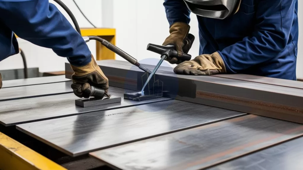
A Welding Procedure Specification (WPS) is essential for achieving precise and high-quality welds. It outlines the steps, parameters, and guidelines that ensure consistent and flawless welding results. But what is a WPS in welding? Simply put, it’s a detailed document that defines the weld specification, including joint configurations, welding process, and filler material. Understanding what a welding procedure specification entails is crucial for both novice and experienced welders. By mastering the principles of a WPS, you can achieve reliable, high-quality welds every time. In this guide, we explore what WPS in welding means, its components, and how it ensures superior performance. Let’s unlock the secrets to perfect welds with this essential tool.
What is Welding Procedure Specifications (WPS) in Welding ?
A Welding Procedure Specification (WPS) is the foundation of successful welding operations. It ensures every weld is precise, consistent, and of high quality. A clear WPS outlines specific processes, materials, and techniques for the welder to follow. This guidance enhances weld quality while promoting safety, efficiency, and adherence to industry standards. Without a proper welding procedure specification, defects, increased costs, and workplace hazards become common challenges.
But what is a WPS in welding? It is a detailed document that plays a critical role in quality control and assurance. A Work Procedure Specification serves as a reference during inspections and audits, ensuring compliance with relevant weld specifications and standards. By following a welding procedure specification, organizations can reduce non-conformance risks, rework, and project delays.
Additionally, a Work Procedure Specification helps train welders, ensuring best practices are consistently followed across teams. It also reassures clients and stakeholders about the reliability of a project. Understanding what a WPS in welding entails demonstrates professionalism and builds trust. Investing in a robust WPS not only benefits current projects but also strengthens long-term business success.
A welding procedure specification is much more than a guideline—it’s a vital tool for quality, safety, and industry excellence.
Welding procedure Specification (WPS)
Components of a Welding Procedure Specification
A Welding Procedure Specification (WPS) is a detailed guide that defines the welding process. It includes critical components such as the welding method, base and filler materials, preheat and interpass temperatures, and post-weld heat treatment requirements. Each section of the WPS provides clear and detailed instructions, ensuring welders understand the exact parameters they must follow.
One essential part of a WPS is identifying the materials. It specifies the grade, type, and thickness of the base metal along with the correct filler metal. These materials directly affect the welding process and the quality of the final weld. By choosing compatible materials and documenting them in the WPS, welders can minimize defects like cracking or incomplete fusion. Understanding what is a welding procedure specification ensures welders follow proper practices.
A WPS also outlines welding parameters and techniques. It includes details like position, voltage, amperage, travel speed, and shielding gas composition. Each of these factors is crucial to achieving high-quality welds. Clear documentation ensures consistent results across projects and welders. Knowing what is a WPS in welding and adhering to it enables precision and reliability. A well-crafted WPS is the backbone of any successful welding operation.
Understanding Welding Codes and Standards
Welding codes and standards play a crucial role in the creation and execution of Welding Procedure Specifications (WPS). These codes are set by organizations such as the American Welding Society (AWS). They also include the American Society of Mechanical Engineers (ASME) and the International Organization for Standardization (ISO). These organizations provide essential guidelines for different welding applications. A deep understanding of these codes is vital for ensuring compliance and achieving high-quality welds.
Each welding code specifies requirements related to materials, processes, testing, and quality control. For example, the AWS D1.1 code governs structural welding of steel, while ASME Section IX outlines qualifications for welding and brazing. Knowledge of these codes enables professionals to develop Welding Procedure Specifications. These specifications meet the necessary standards. This ensures their work is recognized within the industry.
Adhering to welding codes and standards is also critical for the safety and reliability of welded structures. Non-compliance can lead to catastrophic failures, risking injury, loss of life, and significant financial consequences. Welders can ensure the integrity and safety of their projects by integrating the appropriate welding codes into the Welding Procedure Specifications. This protects both themselves and their teams. Additionally, it strengthens the credibility of their work with clients and regulatory authorities.
Advantages of WPS
A Welding Procedure Specification (WPS) is essential for ensuring consistent, high-quality, and safe welding practices. It provides clear guidelines that help meet industry standards and optimize welding efficiency.
Ensures consistency in welding practices, leading to reliable and repeatable results.
Guarantees compliance with industry standards (e.g., AWS, ASME) for regulatory acceptance.
Improves safety by specifying proper techniques, material requirements, and treatments.
Supports quality assurance through clear reference for inspectors and engineers.
Ensures traceability of materials, processes, and testing methods for future audits.
Increases efficiency by reducing errors, minimizing rework, and streamlining training for welders.
Welding procedure Specification (WPS)
How to develop a Welding Procedure Specification ?
Creating a Welding Procedure Specification (WPS) requires a systematic approach that involves gathering information, analyzing variables, and documenting processes.
Identifying Project Requirements
The first step in creating a Welding Procedure Specification (WPS) is to identify the specific requirements of the project. This involves determining the materials involved, the welding process to be used, and any relevant codes and standards. Collaboration with project stakeholders, including engineers and quality assurance personnel, ensures that all necessary considerations are included.
Selecting Welding Parameters and Techniques
After defining the project requirements, the next phase involves selecting the appropriate welding parameters and techniques. This includes choosing the correct filler material, establishing preheat and interpass temperatures, and determining post-weld treatments. Each of these factors can affect the quality of the weld, so thorough research and testing may be necessary to identify optimal settings.
Documenting the WPS
Once the welding parameters and techniques are selected, it is essential to document them clearly in the WPS. Proper documentation provides guidance for welders in the field and ensures consistency across different projects. A well-structured WPS allows for easy reference and clarity during the welding process.
Review and Validation Process
After developing the initial draft of the WPS, a thorough review and validation process is crucial. Consultation with experienced welders and engineers helps to gather valuable feedback and refine the document. This step ensures that all aspects of the WPS meet project needs and industry standards.
Conducting Trial Runs and Mock Welds
Conducting trial runs or mock welds can provide practical insights into the feasibility and effectiveness of the proposed welding procedures. Testing the WPS under real-world conditions helps identify any potential issues and allows for necessary adjustments before full-scale implementation.
Finalizing the WPS
Once feedback is gathered and trial runs are completed, the WPS can be finalized. Rigorous testing and refinement during this stage help ensure high-quality results and mitigate risks during the actual welding process. A well-developed and tested WPS enhances the likelihood of success in the field.
Preparing the Base Metal for Welding
Proper preparation of the base metal is essential for achieving high-quality welds. The quality of a weld is directly influenced by the cleanliness, fit-up, and temperature control of the base metal. Following the right procedures ensures a strong, durable, and defect-free weld. The steps involved in preparing the base metal include cleaning, joint alignment, and temperature management, each of which contributes to the overall success of the welding process.
Base metal Preparation (WPS)
Cleaning the Base Metal
The first step in base metal preparation is cleaning the surfaces to remove contaminants such as rust, oil, paint, and dirt. Contaminants can lead to poor fusion, porosity, and other defects. Effective cleaning methods like grinding, sanding, or chemical cleaning ensure a clean surface free from impurities.
Assessing the Joint Fit-Up
Proper joint design and alignment are vital for achieving a successful weld. Misalignment can result in uneven weld beads, increased stress, and weakened structural integrity. The pieces to be welded must be accurately positioned. They should also be securely clamped in place. This ensures alignment and stability.
Controlling Base Metal Temperature
Temperature control is another critical consideration. Preheating the base metal may be required to prevent issues like cracking and distortion. The Welding Procedure Specification (WPS) provides the recommended preheat temperature and methods for monitoring it during the process. Proper temperature management ensures better weld quality and enhances the performance of the final product.
Selecting the Right Welding Process for Your Project
Choosing the appropriate welding process is a fundamental step in achieving optimal results in any welding project. Various welding techniques are available. These include Shielded Metal Arc Welding (SMAW) and Gas Metal Arc Welding (GMAW). Other options are Flux-Cored Arc Welding (FCAW) and Gas Tungsten Arc Welding (GTAW). Each technique offers distinct advantages and limitations. The selection of the welding process should be based on factors like the materials being welded, the required weld quality, and the specific working environment.
For example, SMAW is ideal for outdoor applications and versatile enough for various materials, making it a popular choice for construction projects. On the other hand, GTAW is preferred for high-quality welds in critical sectors like aerospace and nuclear industries due to its precision and control. By understanding the characteristics of each welding process, welders can make informed decisions that align with the project’s requirements.
In addition to material and quality considerations, the welding position and joint configuration also play a role in selecting the right welding process. Some processes perform better in overhead or vertical positions, while others are limited to flat positions. Evaluating these factors ensures that the welding process chosen meets technical requirements and enhances efficiency.
Ultimately, the correct welding process significantly influences the success of a project. A carefully chosen welding method reduces the risk of defects, minimizes rework, and boosts productivity. This decision, crucial for the development of a successful Welding Procedure Specification, is vital for ensuring effective welding procedure inspection and quality control throughout the project. By taking the time to analyze all options, welders can improve outcomes and streamline the overall welding procedure inspection process. The selection of the right process ensures that welding procedure inspection results in a reliable and high-quality final product.
Essential Variables and Their Impact on WPS
Understanding essential variables is vital when developing a Welding Procedure Specification (WPS). These variables directly influence the welding process and the quality of the final product. Key factors include welding parameters like voltage, amperage, travel speed, and heat input. Each parameter affects the weld differently. For example, increasing voltage creates a wider and flatter weld bead, while adjusting amperage changes penetration depth and weld strength.
The choice of filler material is another critical factor in the Welding Procedure Specification. The filler metal must match the base metals in compatibility and properties. This ensures a strong and durable weld joint. The WPS should clearly specify the filler material’s chemical composition and mechanical properties. These details help the welder achieve the desired weld characteristics.
Environmental conditions also impact the welding process. Variables like temperature, humidity, and wind can alter the behavior of the molten weld pool. For instance, high humidity increases moisture absorption, causing porosity in the weld. To address this, the Welding Procedure Specification outlines steps to monitor and control environmental factors.
By focusing on these essential variables, the Welding Procedure Specification ensures consistent, high-quality welds. Proper attention to these details enhances safety, reliability, and overall project success.
Qualifying a Welding Procedure Specification
Qualifying a Welding Procedure Specification (WPS) is essential for ensuring performance and quality. This process involves testing and verifying that the WPS can produce welds that meet specific requirements. Mechanical tests, such as tensile, impact, and bend tests, evaluate the weld’s strength and ductility. These tests confirm the reliability of the procedure under real-world conditions.
Industry standards, like those from the American Welding Society (AWS) and the American Society of Mechanical Engineers (ASME), guide the qualification process. Organizations must document and record all steps involved. This documentation becomes a valuable reference for future welding operations. By following these standards, organizations ensure that their Welding Procedure Specification complies with required codes.
Successful qualification of a Welding Procedure Specification boosts confidence among welders and stakeholders. Welders can perform tasks with assurance, knowing the procedures are tested and validated. This leads to higher quality and more consistent results. Additionally, clients and regulators trust organizations that adhere to strict qualification protocols.
By thoroughly qualifying a Welding Procedure Specification, companies enhance reliability, meet industry standards, and build credibility. This critical step ensures that welding processes deliver strong and durable results for their intended applications.
Common Mistakes to Avoid in Welding Procedure Specification Development and Implementation
Developing and implementing a Welding Procedure Specification (WPS) requires precision and careful planning. One frequent mistake is failing to research and understand the project’s specific requirements. These include materials, welding processes, and applicable codes. Neglecting these factors often leads to improper settings and poor weld quality, resulting in costly delays and rework.
Another common error is not providing sufficient documentation for the Welding Procedure Specification. A WPS must include clear and detailed instructions that are easy for welders to follow. If the documentation is vague or incomplete, it creates confusion and inconsistencies during welding. Therefore, it is crucial to define every aspect of the Welding Procedure Specification, such as material details, welding parameters, and special project considerations.
Lastly, inadequate training and communication can undermine WPS implementation. Even a well-prepared Welding Procedure Specification will fail if welders lack proper understanding or if updates to the WPS are poorly communicated. To avoid this, organizations must offer training and encourage open communication. This ensures all team members understand the Welding Procedure Specification and can follow it accurately.
By addressing these common mistakes, teams can enhance the effectiveness of their Welding Procedure Specification and achieve high-quality results.
Types of Welding Procedure Specifications
Welding Procedure Specifications (WPS) vary to address different project needs and ensure high-quality welds. Three main types include Preliminary-WPS, Prequalified-WPS, and Standard-WPS (SWPS), each serving unique purposes.
A Preliminary-WPS acts as the initial blueprint for a welding project. It outlines key details, including materials, welding parameters, and joint configurations, serving as the foundation for further development and testing.
The Prequalified-WPS simplifies the process by using preapproved procedures that meet industry standards without requiring additional testing. These are especially useful for saving time and resources while maintaining quality assurance. Welders can confidently rely on these procedures for standard applications.
The Standard-WPS (SWPS) adheres to widely accepted industry norms. It provides standardized welding methods to ensure consistency and compliance across projects. This type is ideal for achieving uniform results and meeting established benchmarks in welding practices.
Together, these WPS types enhance efficiency and ensure reliable outcomes.
Conclusion
In conclusion, a Welding Procedure Specification (WPS) is a vital document that ensures consistent, high-quality, and safe welding practices. By providing clear guidelines on welding processes, materials, and techniques, it helps minimize defects, improves safety, and promotes compliance with industry standards. Understanding the components of a WPS, such as materials, parameters, and techniques, is essential for achieving reliable welds. Adhering to welding codes and standards further strengthens the quality and safety of welded structures. Whether creating or following a WPS, it serves as a critical tool for welding professionals, ensuring precision and efficiency while reducing risks. Ultimately, investing time and effort in developing and implementing a WPS ensures long-term success and quality in welding projects.
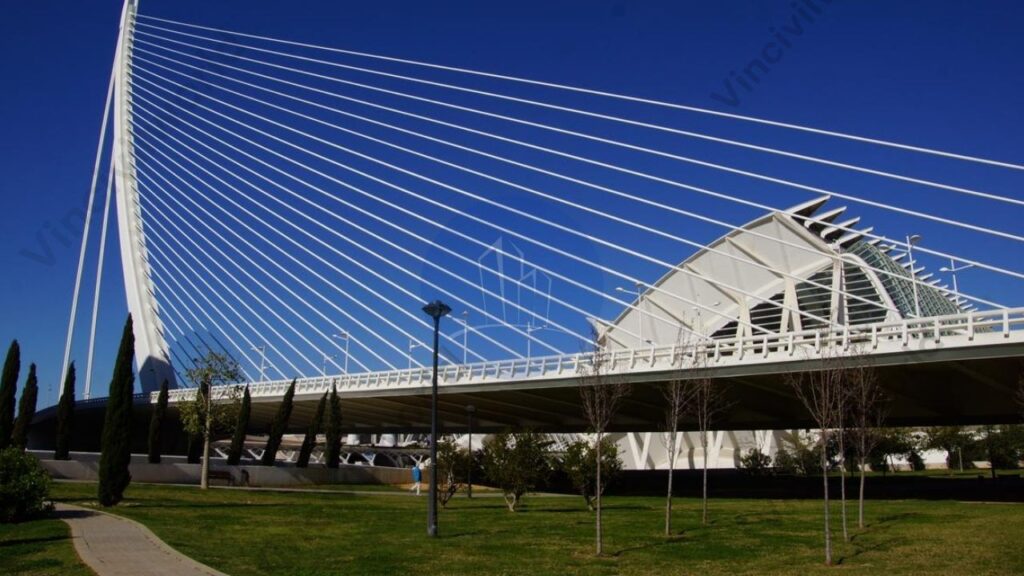
A cable stayed bridge is a modern engineering marvel known for its strength, efficiency, and aesthetic appeal. It uses one or more towers to support the bridge deck through a series of cables, which transfer the load directly to the foundation. Unlike suspension bridges, the cables in a cable stayed bridge connect directly from the deck to the towers in a straight line. This design provides greater rigidity, making it ideal for long spans and challenging terrain.
Cable stayed bridges are widely used for highway crossings, urban connections, and river spans due to their cost-effectiveness and adaptability. The distinctive arrangement of cable-stayed bridge cables creates visually striking structures that enhance the skyline. Some famous cable-stayed bridge examples include the Millau Viaduct in France and the Russky Bridge in Russia. With their efficient load distribution and elegant design, cable-stayed bridges continue to shape modern infrastructure globally.
In this article, we will explore the key components, types, and advantages of a cable-stayed bridge. We’ll also explain how cable stayed bridge cables function, discuss various construction techniques, and highlight notable cable-stayed bridge examples. By the end, you’ll understand why this design is widely used in modern infrastructure projects.
A cable-stayed bridge is a type of bridgewhere the deck is directly supported by cables connected to one or more towers/ pylons . The towers bear the load, and the cables transfer the weight to the foundation, creating a balanced and efficient structure. Unlike suspension bridges, where cables run horizontally between towers, cable-stayed bridge cables are attached directly from the deck to the tower in a straight or fan-like arrangement. This design provides superior stiffness and requires less material, making it cost-effective and suitable for long spans.
Cable-stayed bridges are common in modern infrastructure due to their strength and aesthetic appeal. In India, the Bandra-Worli Sea Link serves as a well-known example of this type of bridge. It showcases the country’s advancements in bridge engineering. Other famous cable-stayed bridge examples include the Sutong Bridge in China and the Øresund Bridge connecting Denmark and Sweden. These bridges exemplify their efficiency in various applications.
How Does a Cable-Stayed Bridge Work?
A cable-stayed bridge works by using a combination of towers (pylons) and stay cables to support the bridge deck. The towers, which are vertical structures, act as the primary load-bearing elements. Stay cables run directly from the towers to the deck in either fan, harp, or radial patterns. These patterns distribute the weight of the bridge and its traffic evenly.
The cables are tensioned to hold up the deck. They transfer the weight from the deck to the towers. The towers then channel the load down to the foundation. This design allows the bridge to span long distances without the need for additional piers. This makes it efficient and cost-effective for crossing large bodies of water or valleys. The tension in the cables and the compression in the towers create a balanced system. It allows the cable-stayed bridge to remain stable under heavy loads. This includes traffic, wind, and environmental stresses.
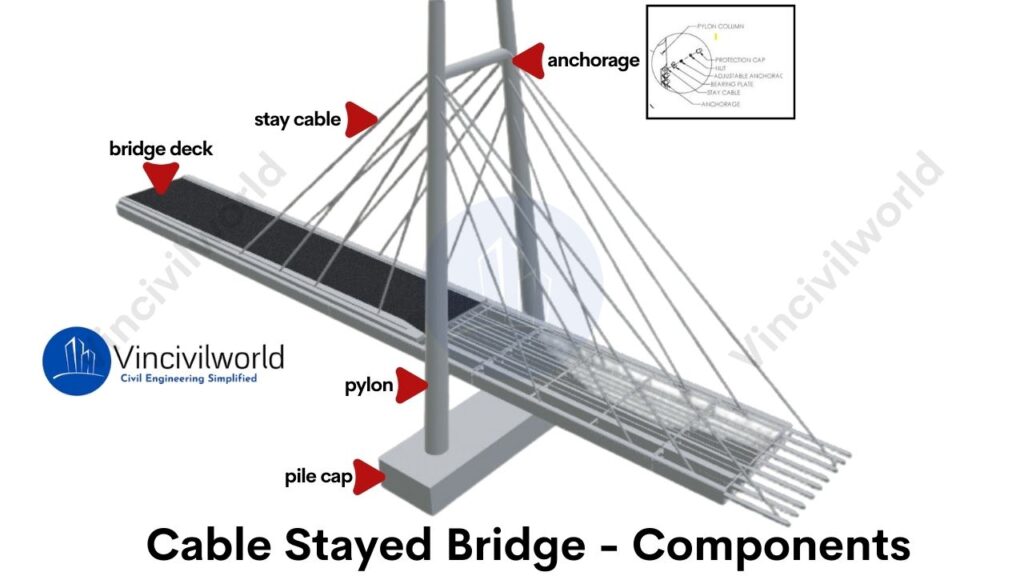
Key Components of a Cable-Stayed Bridge
A cable-stayed bridge consists of several essential components that work together to create a stable and efficient structure. Each part plays a crucial role in supporting the deck and transferring the load through the cable-stayed bridge cables. Below are the key components:
Towers/Pylons
Stay Cables
Deck Structure
Anchorages
Towers/Pylons
Towers, also known as pylons, are the vertical structures that support the cable-stayed bridge cables. They carry the majority of the load by transferring it to the foundations. Towers are usually made of concrete or steel, depending on the bridge design. A well-known example is the Bandra-Worli Sea Link in India, where towering pylons define its unique structure.
Types of Towers (Pylons)
Cable-stayed bridge towers come in various shapes based on design needs and aesthetics. Common types include A-shaped, H-shaped, and single-column towers. A-shaped towers, like those seen in the Bandra-Worli Sea Link in India, provide stability for long spans. H-shaped towers offer simplicity and strength, while single-column towers are ideal for minimalist designs. These towers bear the load of the thereby ensuring the structure’s integrity.
Stay Cables
Stay cables are the cables that directly connect the deck to the towers. These cables carry the weight of the bridge deck and the traffic. In cable-stayed bridges, the cables are arranged in different patterns, like fan or harp styles. These cables allow for flexibility and strength, ensuring the stability of the bridge.
These cables are typically made of high-strength steel strands or parallel wire strands for durability. Stay cables are encased in plastic sheaths to protect against corrosion. They are then grouted with special materials. This process further increases their lifespan and resistance to environmental damage.
Types of Stay Cables
Stay cables are arranged in different patterns, depending on the bridge design. The main types include fan-shaped, harp-shaped, and radial. In fan-shaped designs, the cables spread out from a single point at the top of the tower. In harp-shaped designs, the cables run parallel, creating a clean, sleek appearance. Radial patterns are used for smaller spans, with cable-stayed bridge cables directly supporting the deck.
Deck Structure
The deck structure forms the road or walkway of the cable-stayed bridge. It is supported by the stay cables and often consists of steel or reinforced concrete. The deck must distribute the load evenly across the bridge. In many cable-stayed bridges in India, the deck is designed to handle heavy vehicular traffic. It can also withstand environmental conditions.
Types of Deck Structures
Decks in cable-stayed bridges can be constructed using steel, concrete, or composite materials. Concrete decks are heavy but offer high durability, while steel decks are lighter, making them suitable for longer spans. Composite decks, combining steel and concrete, offer the best of both worlds, balancing weight and strength. The deck structure must efficiently transfer loads to the stay cables and towers.
Decks in cable-stayed bridges can be constructed using steel, concrete, or composite materials. Concrete decks are heavy but offer high durability, while steel decks are lighter, making them suitable for longer spans. Composite decks, combining steel and concrete, offer the best of both worlds, balancing weight and strength. The deck structure must efficiently transfer loads to the stay cables and towers.
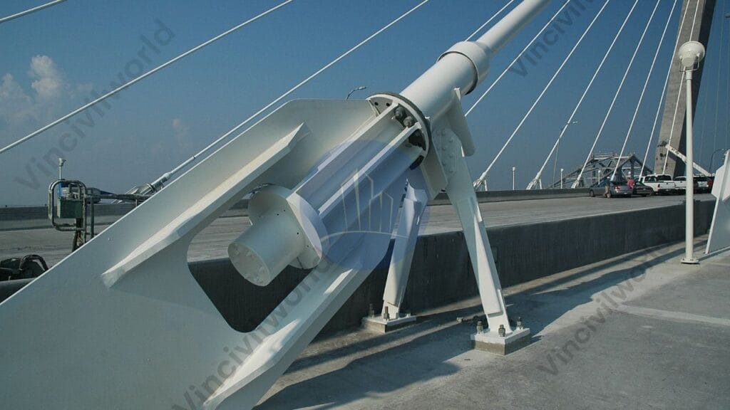
Anchorages
Anchorages are crucial in securing the stay cables to the deck and the towers. They ensure that the load is evenly transferred and that the cables remain in tension. Proper anchorage design is vital to prevent movement in the cables, ensuring the bridge’s durability and long-term stability.
Types of Anchorages
Anchorages are essential for securing the stay cables to the deck and towers. The two main types are external and internal anchorages. Inspecting and maintaining external anchorages is simpler due to their visibility, while embedding internal anchorages within the deck or tower offers added protection. Both types ensure the cable-stayed bridge maintains its tension and stability under varying loads.
Types of Cable-Stayed Bridges
Cable stayed bridges are classified based on the following basis
Based on the Arrangement of Pylons
Based on the shape of Pylons
Based on Cable Arrangements
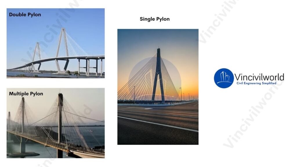
Based on the Arrangement of Pylons
Cable-stayed bridges can be classified by the arrangement of pylons (towers) used to support the deck. The most common types include single-pylon bridges. They have a central tower supporting cables that radiate outward. There are also double pylon bridges and multiple-pylon bridges, which feature two or more pylons placed along the bridge deck. Another variation is asymmetric pylon bridges. The pylons are of different heights or placed off-center. This accommodates specific design needs or terrain constraints.
Multiple-Tower
Multiple-tower cable-stayed bridges use two or more pylons to support longer spans. Engineers often use this type of bridge for large river crossings. These areas require extensive span coverage. Multiple towers distribute the load across a larger area.
Single-Tower
Single-tower cable-stayed bridges feature a single pylon or tower that supports the entire bridge structure. Consequently, narrow waterways or urban environments with limited space are ideal for these bridges. In addition, they provide a sleek and minimalist design.
Double Pylons
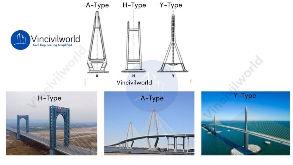
Based on the shape of Pylons
H-Shaped Pylons: These pylons feature two vertical legs. A horizontal beam connects them at the top. This design offers high stability and evenly distributes forces.
A-Shaped Pylons: The pylons are tapered at the top. They resemble the letter “A,” which gives a more streamlined appearance. This design efficiently channels forces down the legs.
Diamond-Shaped Pylons: These pylons are wider at the base and converge near the top, forming a diamond shape. They offer a unique aesthetic and strong structural support.
Y-Shaped Pylons: These pylons resemble the letter “Y.” They have a single leg splitting into two arms at the top. This design offers both flexibility and strength.
Each shape provides distinct structural advantages. The choice depends on the specific needs of the bridge design, aesthetics, and load distribution requirements.
Based on Cable Arrangements
Cable arrangements in cable-stayed bridges generally follow three main patterns:
Radial (fan): Cables radiate from the top of the pylon to various points along the deck, creating a fan-like pattern.
Parallel (harp): Cables are attached at regular intervals along the pylon and deck, forming a parallel arrangement.
Semi-fan: A hybrid design where cables partially fan out but with more uniform spacing, balancing aesthetics and structural efficiency.
Radial Pattern
The cables radiate outward from the pylon to the deck, forming a fan-like shape. This arrangement offers efficient load distribution.
Harp/parallel Pattern
The cables are arranged in a parallel pattern, resembling the strings of a harp. This configuration is commonly used for bridges with a central pylon
Fan Pattern
In a fan pattern, stay cables converge at the top of the tower, spreading out to the deck in a fan-like arrangement. Engineers commonly use this design for cable-stayed bridges with shorter spans, offering both strength and visual distinction.
Advantages of Cable-Stayed Bridges
Cable-stayed bridges offer numerous benefits due to their efficient design and versatility. Moreover, they are ideal for long spans and challenging terrains, as they provide both structural stability and aesthetic appeal. Below are the key advantages:
Fast Construction
The modular construction process of cable-stayed bridges allows for quicker building, reducing disruptions to surrounding areas and environments.
Cost-Effective Construction
Cable-stayed bridges use fewer materials. They require less maintenance compared to suspension bridges. This results in lower construction costs and long-term maintenance costs.
Efficient Load Distribution
Stay cables directly transfer the deck’s load to the towers. This reduces the need for multiple support piers. It simplifies construction and allows for longer spans.
Versatile Design
Cable-stayed bridges offer flexibility in design. They adapt to different structural and architectural needs through various cable arrangements. These arrangements include fan, harp, or radial patterns.
Aesthetic Appeal
The visible arrangement of cable-stayed bridge cables creates a striking, modern look. It enhances the visual landscape of urban or natural settings.
Challenges and Limitations of Cable-Stayed Bridges
While cable-stayed bridges offer many advantages, they also come with certain challenges that impact their design, construction, and long-term performance.
Complex Construction Techniques
Building cable-stayed bridges requires specialized engineering knowledge and equipment. The tensioning of cables, alignment of towers, and precision needed for the cable-stayed bridge cables require high-level expertise. This expertise can increase the complexity and cost of construction.
Maintenance Requirements
Although durable, cable-stayed bridges require regular inspections and maintenance, particularly for the stay cables. Environmental factors like corrosion and wind-induced vibrations can affect cable performance. These issues lead to increased maintenance efforts. This ensures the long-term stability of the structure.
Wind and Seismic Vulnerability
They are sensitive to strong winds and seismic activity. The flexibility of the cables can lead to vibrations or oscillations. If not managed through proper dampening systems, these vibrations may compromise the structure’s stability during severe weather or earthquakes.
Accumulation of snow
The cable-stayed bridges will accumulate ice due to environmental conditions. This ice will cause great harm to the traffic safety below the bridges.
High Initial Costs
These structures are generally cost-effective in the long run. However, they can incur high initial construction costs. This is due to the specialized materials and engineering that they require. The use of advanced materials for stay cables and pylons adds to the upfront expense of the project.
Construction Techniques for Cable-Stayed Bridges
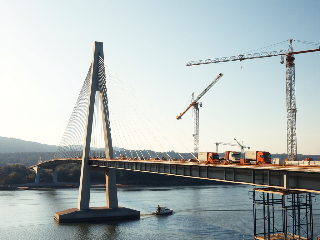
Cable-stayed bridges require precise construction techniques to ensure structural integrity and stability. The process begins with the construction of the towers, which are the main vertical supports. These towers must be strong enough to handle the immense forces transmitted by the cables. Once the towers are in place, deck sections are incrementally installed, typically using a cantilever method. This involves placing deck segments starting from the towers and progressing outward in both directions to maintain balance.
The construction team anchors the cables to the deck and tower, supporting the deck as the build progresses. They continuously adjust the cable tension to ensure the deck stays level. High-strength steel cables are essential. They transfer the load from the deck to the towers. This reduces bending moments in the deck structure.
Cable stayed bridge under construction
The construction process also requires careful consideration of material properties and cable tension forces, with adjustments often calculated using advanced methods like finite element analysis. Designers must give the bridge deck high torsional rigidity to resist twisting forces caused by uneven loads, ensuring long-term durability. Regular monitoring and adjustments during the construction phases are critical to maintaining the bridge’s alignment and stability
Comparison Between Cable-Stayed and Suspension Bridges
Feature
Cable-Stayed Bridges
Suspension Bridges
Structural Design
Cables directly connect the deck to the towers.
Cables run from towers to anchorages, supporting the deck via smaller vertical cables.
Main Cables
Fewer, shorter cables, anchored directly to the towers.
Long, continuous cables running over towers, anchored at both ends.
Cable Arrangement
Radial or fan-shaped pattern from towers to deck.
Vertical hangers suspend the deck from main cables.
Tower Height
Towers are shorter compared to suspension bridges.
Taller towers are required to support the long, continuous main cables.
Span Length
Best suited for medium spans (typically 200 to 1,000 meters).
Suitable for long spans (over 1,000 meters).
Construction Method
Faster to build as deck sections and cables are installed incrementally.
Requires extensive anchoring and time-consuming construction, especially for long spans.
Deck Support
Cables directly support the deck, providing greater stiffness.
The deck is supported by vertical hangers, allowing for more flexibility.
Torsional Stiffness
Higher torsional stiffness, making it less prone to twisting under loads.
Lower torsional stiffness, making it more flexible and vulnerable to twisting.
Cost
Generally more economical for medium spans.
Higher construction costs, particularly for long spans.
Maintenance
Lower maintenance costs due to fewer cables and less complex structure.
Higher maintenance costs due to more extensive cable systems and anchorages.
Aesthetics
Modern, sleek appearance with visible cables fanning from the towers.
Iconic and graceful with sweeping main cables and vertical hangers.
Examples
Millau Viaduct (France), Vasco da Gama Bridge (Portugal)
Golden Gate Bridge (USA), Akashi Kaikyō Bridge (Japan)
This comparison highlights the key differences in design, function, and applications between cable-stayed and suspension bridges
Famous Examples of Cable-Stayed Bridges Around the World
Here’s a list of famous cable stayed bridges around the world:
Millau Viaduct (France) – One of the tallest bridges globally, known for its elegance and engineering.
Vasco da Gama Bridge (Portugal) – The longest bridge in Europe, spanning 12.3 km over the Tagus River.
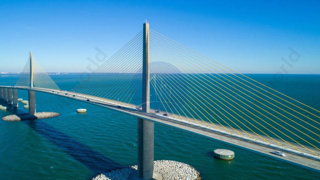
Sunshine Skyway Bridge (USA) – An iconic cable-stayed bridge in Florida, noted for its striking design.
Sutong Bridge (China) – Famous for its long span, once the longest cable-stayed span in the world.
Russky Bridge (Russia) – Holds the record for the longest cable-stayed span, connecting Russky Island to mainland Russia.
These bridges exemplify cutting-edge engineering and aesthetic appeal.
Applications of Cable-Stayed Bridges in Modern Infrastructure
Here’s a list of applications in modern infrastructure:
Highway Crossings: They efficiently connect major roadways, facilitating smoother traffic flow.
Railway Bridges: Ideal for spanning railway lines, minimizing disruptions to train services.
Urban Infrastructure: Often used in city planning to enhance connectivity between districts.
Waterway Crossings: They provide essential links over rivers and lakes, supporting commercial and recreational navigation.
Pedestrian and Bicycle Paths: Some designs incorporate dedicated lanes for non-motorized traffic, promoting eco-friendly transport.
Iconic Landmarks: Their aesthetic appeal makes them popular for constructing visually striking landmarks.
These applications demonstrate the versatility and effectiveness in various infrastructure projects
The Future of Cable-Stayed Bridges
The future of cable-stayed bridges is promising, driven by advancements in materials and engineering techniques. Innovations such as high-strength steel and fiber-reinforced polymers will enhance durability and reduce maintenance costs. Additionally, the integration of smart technologies, like sensors for real-time monitoring, will improve safety and efficiency. As cities continue to expand, cable-stayed bridges will meet infrastructure demands and maintain aesthetic appeal. This makes them increasingly relevant in modern urban planning.
Key takeaways
Here are the key takeaways
Efficient Load Distribution: They distribute loads effectively through towers and stay cables.
Aesthetic Appeal: Their unique design contributes to the visual beauty of infrastructure.
Long Spans: Capable of spanning long distances without multiple piers.
Cost-Effective Construction: Typically cheaper and quicker to construct compared to other bridge types.
Key Components:
Towers: Support the bridge deck.
Stay Cables: Connect the towers to the deck.
Deck Structures: The surface of the bridge.
Anchorages: Secure the cables.
Configuration Variations: Includes fan, harp, and radial patterns to meet different design requirements.
Advantages: Faster construction and lower maintenance costs.
Challenges: Sensitivity to wind and seismic activity.
Notable Examples: Includes the Millau Viaduct and the Bandra-Worli Sea Link, illustrating their significance in modern infrastructure.
Conclusion
Cable-stayed bridges are remarkable engineering achievements characterized by their efficient load distribution and aesthetic appeal. They use towers to support the bridge deck. A system of stay cables allows for long spans without multiple piers. This design not only enhances structural rigidity but also offers cost-effective construction. Key components include towers, stay cables, deck structures, and anchorages. They come in various configurations such as fan, harp, and radial patterns to suit different needs. Cable-stayed bridges offer advantages like faster construction and lower maintenance costs. However, they also face challenges related to sensitivity to wind and seismic activity. Notable examples include the Millau Viaduct and the Bandra-Worli Sea Link, showcasing their significance in modern infrastructure.
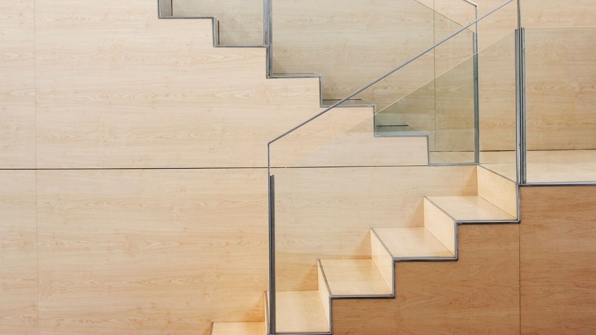
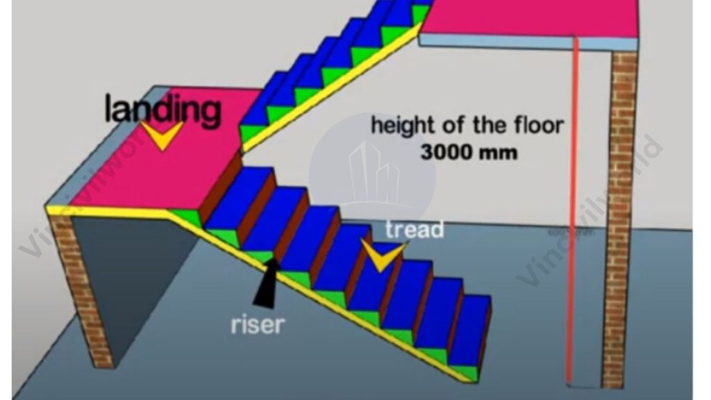
Staircase components are essential parts that work together to create a functional and safe staircase. The stair function is to provide a stable and accessible means of moving between levels.This is achieved through various key staircase components. Treads, the horizontal surfaces, provide a step for the foot, while risers are the vertical elements that define the step height. Stringers serve as the structural supports that hold the treads and risers in place. Handrails offer safety and stability for users, while landings provide resting spaces or changes in direction. Each of these components of a staircase contributes to both the staircase function and the overall design, ensuring comfort, safety, and efficiency.
The components of the staircase must fulfill specific functional requirements. . A staircase is one of the most important structural elements of a building. The primary function of a staircase is to facilitate movement from one floor to another. Staircases can be straight or curved and made of reinforced concrete, steel, wood, stones, and other materials. Staircases enhance the aesthetic appearance of the building in addition to providing access between floors.
It is necessary to understand the various components of the staircase as well as its functions when detailing it. This article discusses the components of a staircase and their functions
The staircase is made of several components and each component is associated with specific functional requirements. Following are the components of a staircase.
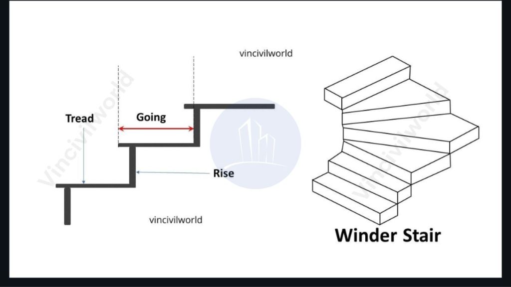
Tread – Horizontal Components of the staircase step
A tread is a major horizontal component of the staircase where we put our feet. The depth of tread is the distance between the staircase’s inner and outer edges. The tread width is the distance along the width of the steps. Generally, the tread of the staircase should be 270 mm in residential buildings and 300 mm in public buildings.
Rise – Vertical components of the staircase step
A rise in a staircase is the vertical component of the staircase step. It serves as a support for the treads. The vertical distance between successive treads is referred to as the rise. Generally, the riser should be 150 mm for public buildings and 190 mm for residential buildings.
Step – Combination of vertical and horizontal components of the staircase
Steps are the combination of treads and risers. Similarly, a pair of risers and tread makes a step. Basically, it is the functional unit of a staircase.
Curtail step
The curtail step is the first step in the staircase. The width of the curtail step can be more than the normal steps. The curtail step is another major components of the staircase which acts as a base for the staircase.
Nosing
The edge of a stair tread that projects out horizontally is known as the nosing. In general, nosing has a rounded edge. However, the length of the nosing should not exceed 1.5″. Basically, nosing enhances the appearance of the staircase. The line of nosing is the imaginary line that connects the nosing. This line runs parallel to the stairwell’s incline.
Flight
Flight is a component of the staircase that consists of a series of steps. Basically, it is the total steps between the two landings. Generally, flights consist of 8 to 10 steps.
Landing – Crucial components of the staircase
Landing is the horizontal space between two flights. It acts as a space to change the direction of the staircase. Generally, the minimum height of the landing should be 7 feet. The width of a landing is the distance between one end to the other end, which is normally equal to the width of the step.
Going
Going is the distance measured from the nosing of successive treads. It is the horizontal distance between the consecutive risers.
Winders
Winders are tapering steps. That is one end of the step is narrower than the other. Likewise, It is a type of step which helps in changing the direction of the staircase. Basically, it acts as a landing. However, Spiral staircases consist of a series of winders.
Railing
The railing is a components of staircase which is used for holding hands. Generally, it is inclined and parallel to the slope of the staircase. Similarly, they act as protective bars. Generally, they are made using timber.
Baluster
The baluster is the vertical component of the handrail. Basically, balusters act as a support for the railing.
Run
The total length of the series of flights including the length of landing is the run of a staircase
Soffit
The bottom part of the staircase component is the soffit. Basically, this place is suitable as a storage area.
Stringer
The components in the staircase which support the risers and treads are the stringer. There are two types of stringers,
Cut or type stringers
Closed or Housed type stringers
They are parallel to the slope of the staircase.
Waist
The staircase is rest on a thick RCC slab. This RCC slab is known as the waist slab. It is perpendicular to the soffit of the staircase.
Conclusion:
In summary, the components of a staircase—such as treads, risers, stringers, handrails, and landings—work together. They ensure functionality, safety, and design coherence. Each element plays a critical role in providing a stable and accessible means of movement between floors. It also enhances the overall aesthetic appeal of the building. Understanding these components is crucial for designing staircases. It is also vital for constructing staircases. These components ensure that staircases meet safety standards. They also suit the specific needs of the building. By considering the design and function of each component, designers can create staircases that are practical. They can also enhance the architectural beauty of a space.
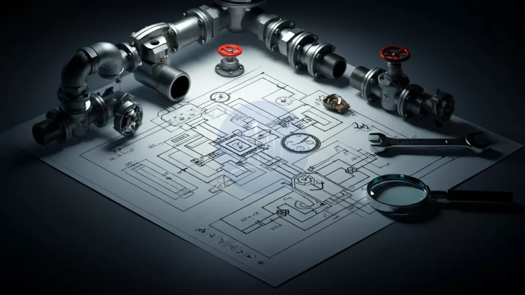
Piping isometric drawings are essential tools in the engineering and construction of pipeline systems. They provide a three-dimensional representation of pipelines in a two-dimensional format, helping engineers visualize complex layouts. Unlike other drawing styles, piping isometric drawings depict the height, width, and depth of the pipeline. This depiction allows for precise planning and communication among project teams. These drawings are critical for pipeline fabrication and ensure that installations align with design specifications.
In this article, we will explore piping isometric drawing symbols. We will also cover isometric pipe drawing symbols and how to read isometric piping drawings. Understanding these symbols and techniques is crucial for accurate and effective pipeline design and construction.
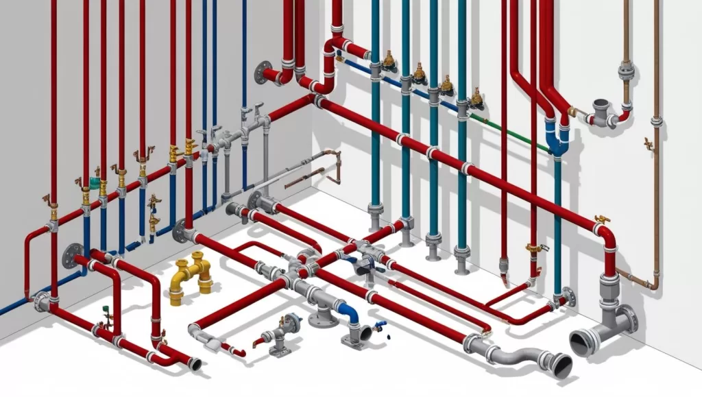
Piping isometric drawings are crucial in pipeline design, providing 3D representations in a 2D format. They simplify complex layouts, enhance visualization, and ensure accurate fabrication with standardized symbols and clear details.
Piping isometric drawing symbols
Key features of isometric drawings for piping include:
A 30-degree angle projection for all axes to show depth.
Use of Standardized Symbols: Incorporates symbols for pipes, valves, elbows, and fittings, ensuring consistency and ease of understanding.
Precise Dimensions: Includes detailed measurements and angles, aiding accurate fabrication and assembly.
Annotations and Notes: Offers material specifications, pipe sizes, weldinginstructions, and operational details.
Flow Direction Indicators: Utilizes arrows and markings to show the flow direction of fluids within the pipeline.
Simplified Layout Interpretation: Easier to read compared to other technical drawings, helping teams visualize complex configurations.
Fabrication-Friendly Design: Acts as a guide for manufacturers, reducing errors and material wastage.
Compliance: Ensures adherence to design and construction standards, supporting effective project execution.
Inclusion of key elements such as piping symbols for isometric drawings, directional arrows, and dimension lines. These features make isometric drawings of pipelines a preferred choice for complex projects.
Importance of Isometric View in Piping
The isometric view in piping is a visual representation technique. It shows all three dimensions length, width, and height—at equal scales. This unique perspective simplifies complex pipeline layouts, making it easier for engineers to interpret designs accurately. Isometric views provide a clear and comprehensive depiction of the pipeline geometry. This clarity allows engineers to identify potential design challenges or conflicts before construction begins. This visualization method enhances communication among project teams. It ensures that intricate systems are easier to comprehend. This approach ultimately saves time and reduces errors in fabrication and installation processes. The isometric view in piping plays a vital role in streamlining project execution and improving overall design accuracy.
Piping isometric drawing symbols act as a universal language for engineers and fabricators.
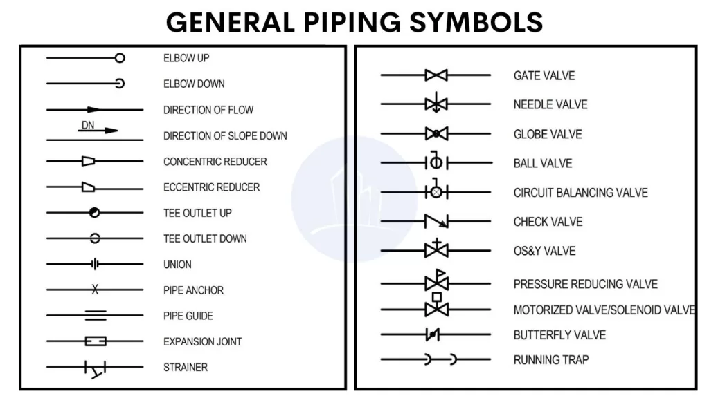
Piping isometric drawings represent three-dimensional pipeline systems on a 2D plane. They offer a clear understanding of complex pipe routing across multiple planes. These drawings use single-line representations of pipe centerlines to measure dimensions. They incorporate symbols for components like valves, flanges, reducers, and welds. Common symbols include:
Isometric drawing for piping
Valves: Represented by geometric shapes such as circles or rectangles with annotations.
Flanges: Depicted as two parallel lines intersecting the pipe.
Reducers: Indicated by a tapered line connecting different pipe diameters.
Elbows: Shown with angular bends.
How to Read Piping Isometric Drawings
Understanding isometric pipe fittings drawings is crucial when handling complex pipeline systems. These drawings offer a three-dimensional visualization of piping layouts on a two-dimensional surface. They aid engineers, designers, and operators in effective planning and execution. A standard 30-degree angle is applied to the axes, which ensures equal foreshortening of length, width, and height.
This creates a proportional and clear perspective. This approach provides precise information about pipe routes, dimensions, and connection details. It makes it easier to analyze and implement designs. Additionally, it minimizes errors during construction or maintenance. Mastery of isometric pipe fittings drawings enhances efficiency and communication among all stakeholders in pipeline projects.
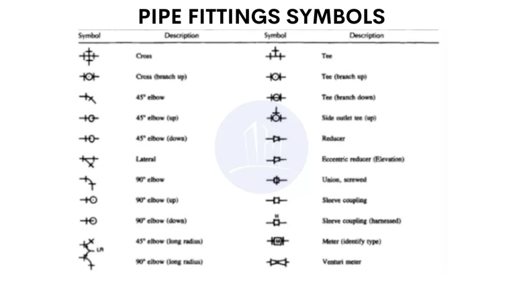
Representation of pipe fittings drawings
Piping isometric drawings use standardized symbols to represent different pipe fittings and components. These symbols convey critical information about the type, size, and orientation of pipes, valves, and other equipment. Recognizing these symbols is essential for accurately interpreting the layout and functionality of the piping system depicted in the drawing.
Piping isometric drawing symbols
Representation of pipe fittings and pipe materials
Piping isometric drawings specify the material of the pipes, such as carbon steel, stainless steel, copper, or PVC. This information is crucial for understanding the system’s properties and requirements.
In piping isometric drawings, pipes are represented as single lines to simplify the layout. These lines include key information such as pipe size, material, and specification. Arrows indicate flow direction, while symbols represent fittings, valves, and connections. The drawings maintain a 30-degree angle for clarity and accurate visualization.
Representation of pipe fittings in piping isometric drawings
Each fitting is represented by a unique symbol on the isometric drawing. This allows you to quickly identify the components. You can also see their orientation within the system.
Pipe fittings drawings
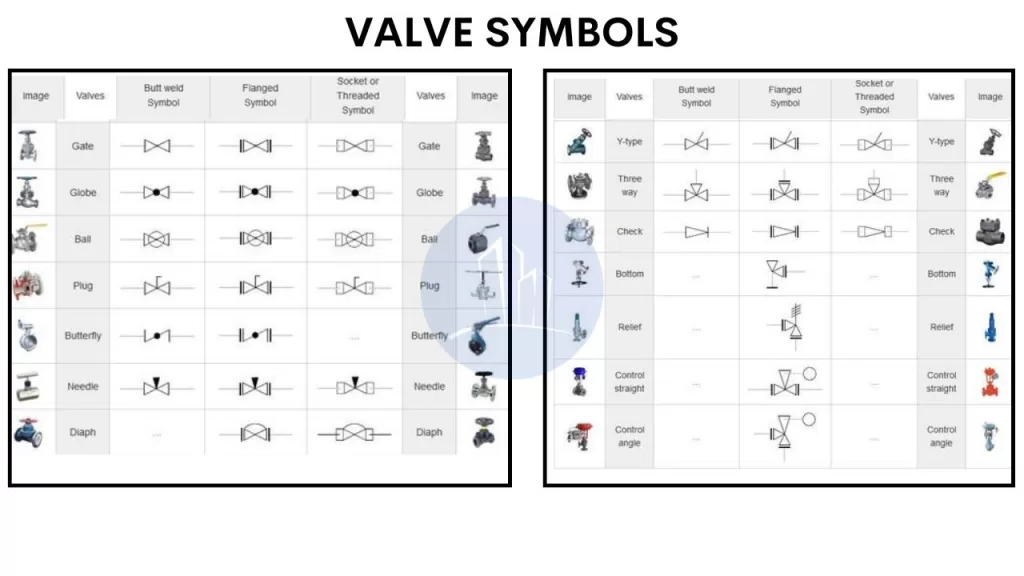
Valve Symbols
Piping isometric drawings use standardized symbols to represent different types of valves, such as ball, gate, and globe valves. These symbols are typically color-coded to distinguish the valve type.
Pipe fittings drawings -Valves
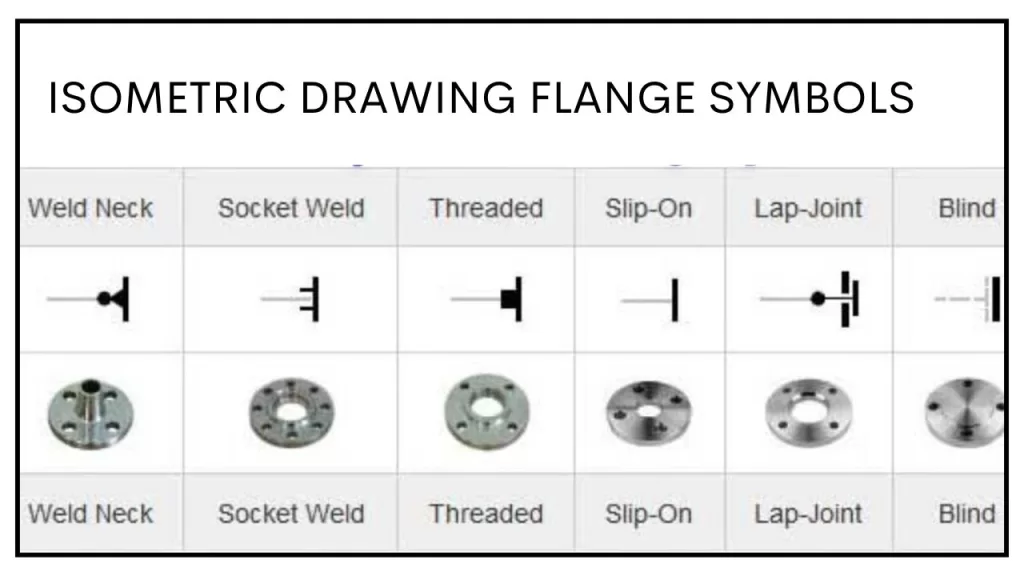
Flanges symbols
Flange symbols in piping isometric drawings represent the connection points between pipes or pipe and equipment. These symbols vary based on flange type.
Piping isometric drawing symbols (Flanges)
Instrument Symbols
Instruments like pressure gauges, thermometers, and flow meters are also depicted using standardized symbols in isometric drawings. These help identify the location and type of instrumentation along the piping system.
Instruments
Applications of Isometric Drawings in Piping Systems
Piping layout drawings provide critical information essential for designing and constructing pipeline systems. Here’s what can be obtained from them:
Pipe Routing: Exact pathways of pipes, including elevations and orientations.
Equipment Locations: Placement of machinery and fixtures in relation to the piping system.
Material Specifications: Details about pipe materials, insulation, and coatings.
Dimensions: Measurements of pipe lengths, offsets, and distances between components.
Fittings and Connections: Types of joints, flanges, and fittings required.
Support Systems: Locations and types of pipe supports, hangers, and anchors.
Flow Direction: Indicated by arrows to ensure proper operation.
Valves and Instruments: Placement and specifications of valves, gauges, and control devices.
Safety Features: Emergency shut-off systems and pressure-relief valves.
Compliance Data: Adherence to standards, codes, and regulations.
This ensures accuracy and efficiency in pipeline installation and maintenance.
Annotations and Labels in Piping Layout Drawings
Pipe Size and Material: Specifies the diameter and material (e.g., steel, PVC) for each pipe, ensuring compatibility.
Flow Direction: Uses arrows to indicate the direction of fluid or gas flow within the system.
Equipment Tags: Labels machinery and equipment with unique identifiers for easy referencing.
Elevation Indicators: Highlights the height or depth of pipes, critical for alignment.
Connection Details: Annotates welds, flanges, or threaded connections for assembly.
Valve Types and Numbers: Identifies valve locations, types (e.g., gate, globe), and tag numbers for functionality.
Support Annotations: Labels pipe supports, hangers, or brackets with their specifications.
Insulation and Coating: Notes areas requiring thermal insulation or corrosion-resistant coatings.
Instrument Tags: Marks sensors, gauges, and monitoring instruments with unique labels.
Safety Instructions: Includes warnings, emergency shutoff points, and safety compliance notes.
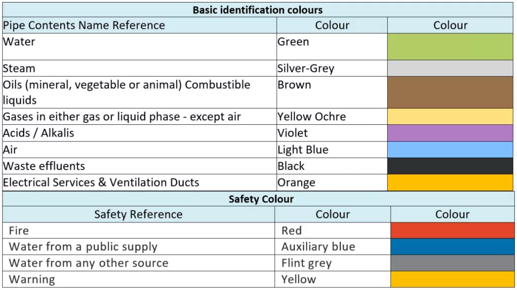
Color Code in Piping Systems
Color coding in piping systems is a standardized method to identify the contents of pipelines for safety and operational efficiency. It aids in quick recognition during maintenance and emergencies.
color codes
Fluid Type Identification: Different colors represent various fluids like water, steam, oil, or gases.
Hazard Awareness: Highlights dangerous contents, such as flammable or toxic substances.
Directional Arrows: Used alongside color codes to indicate the flow direction.
Compliance Standards: Adheres to codes like ANSI/ASME A13.1 or ISO standards for global consistency.
Maintenance Assistance: Simplifies troubleshooting by providing instant recognition of pipeline contents and purpose.
A well-read piping isometric drawing minimizes errors in pipeline fabrication and installation.
Applications of Isometric Drawings in Piping Systems
Isometric drawings are vital for designing, installing, and maintaining piping systems, providing comprehensive details about dimensions, layout, and materials in a three-dimensional perspective.
Applications
Design Visualization: Offers a clear 3D view of piping layouts, simplifying complex designs.
Installation: Guides field teams on accurate pipe placements and alignment.
Material Estimation: Lists materials required for efficient planning and procurement.
Maintenance and Repair: Identifies pipe locations and connections for quick repairs.
Conflict Resolution: Highlights spatial clashes to prevent on-site issues.
Compliance: Ensures designs meet safety and engineering standards.
Steps to Create Isometric Drawings for Piping
Creating isometric drawings for piping involves several key steps to ensure precision. Start by preparing the piping layout, including all components like valves, elbows, tees, and pumps. Set up the isometric grid at the required scale, using a 30-degree angle to represent the three dimensions. Define pipe diameters to mark the size of each pipe accurately. Next, plot the piping components, including pipe runs, fittings, and equipment, using the grid. Add details like material types, flow direction, and any additional specifications. Finally, review and validate the drawing for accuracy, ensuring it aligns with the engineering design.
Various software tools can streamline this process. AutoCAD is great for both 2D and 3D piping designs with isoplane settings. Revit, used in BIM-based designs, generates detailed isometric views and integrates with other data. Tools like SolidWorks, SmartPlant 3D, and MicroStation enhance 3D modeling, offering automation and flexibility for efficient, accurate isometric piping designs.
Common Challenges in Isometric Piping Drawings
Challenges in isometric drawings for pipelines include:
Scaling Issues: Misinterpretation of dimensions is common when scaling the drawing. Accurate scaling is crucial to ensure that components fit as designed in the real-world installation.
Symbol Miscommunication: Incorrect or inconsistent use of isometric pipe drawing symbols can lead to errors. Adhering to industry standards ensures clarity and prevents confusion during the construction or maintenance stages.
Complexity in Detailing: Representing multiple components such as valves, joints, and fittings in a three-dimensional system can be overwhelming, requiring careful attention to maintain accuracy and detail.
Alignment and Layout: Improper alignment of pipes and components can disrupt the flow of the design and cause potential installation issues.
Comparison of Isometric and Orthographic Drawings
The Piping isometric drawings and orthographic drawings serve different purposes:
Isometric Drawings: Provide a 3D perspective, showing depth, width, and height in a single view, ideal for visualizing complex systems.
Orthographic Drawings: Focus on individual planes (top, side, front), giving precise measurements for construction but lacking the 3D perspective.
Complex Layouts:Isometric views in piping offer superior clarity and help in understanding the spatial arrangement of components.
Piping Isometric Drawing Standards and Guidelines
International Standards:
ISO 128-30:2017 – This standard outlines the general principles for creating isometric drawings. It includes the use of a 30-degree angle for projections. These projections represent three-dimensional objects on a two-dimensional plane. It ensures uniformity across industries and geographical boundaries.
ASME Y14.5-2009 – The American Society of Mechanical Engineers (ASME) standard provides guidelines on dimensional tolerances, including isometric drawings. It also covers how to represent pipe sizes, materials, and flow directions.
ANSI/ASME B31.3 – This standard for Process Piping explains how isometric drawings should accurately represent the piping system. It includes component layout and material specifications. Additionally, it standardizes symbols for valves, flanges, and fittings.
ISO 5457:2012 – This specifies the size of drawings. It includes the standard sheet size used for isometric drawings. This ensures they are universally recognizable and maintain clarity.
Indian Standards:
IS 696:1972 – The Indian Standard for Engineering Drawing lays the foundation for isometric projections. It also standardizes the use of symbols for different components like valves, elbows, and flanges. It is consistent with international practices in dimensioning and symbol representation.
IS 10701:1983 – This standard applies to the design and drafting of piping systems. It offers specific guidelines for the representation of isometric drawings. It also includes material codes and component alignment.
IS 1235:1982 – This standard focuses on the quality of engineering drawings. It establishes conventions for piping isometric drawings, including scale and symbol usage. These conventions ensure clear communication in the installation and maintenance of piping systems
By adhering to these standards, designers and engineers can create isometric drawings that are clear and standardized. These drawings are easily interpretable across regions and industries.
Three Main Rules in Isometric Drawing
In isometric drawing, three main rules ensure accuracy and clarity:
30-Degree Angle: The drawing is created using a 30-degree angle to show all three dimensions (length, width, and height) equally foreshortened.
Equal Scaling: All axes should be scaled equally to maintain proportionality and prevent distortion.
Straight Lines: Maintain straight lines for pipes and components, ensuring accurate measurements and preventing confusion.
These rules help in creating precise, easy-to-read representations of three-dimensional systems on a two-dimensional plane.
Key Takeaways: Piping Isometric Drawings and Symbols
Essential for Piping: Isometric drawings provide a 3D representation of complex pipeline systems on a 2D plane, showing height, width, and depth for precise planning and communication.
Standardized Symbols: These drawings use universally recognized symbols for components like valves, flanges, and fittings, ensuring clarity and consistency in interpretation.
Simplified Visualization: The isometric view simplifies complex layouts, aiding engineers and project teams in visualizing and understanding intricate pipeline configurations.
Fabrication and Installation Guidance: Precise dimensions, annotations, and material specifications in isometric drawings guide accurate fabrication and installation processes. This reduces errors and ensures compliance with design requirements.
Effective Communication: Piping isometric drawings facilitate clear communication among engineers, fabricators, and installers, ensuring accurate execution and minimizing potential conflicts.
Standards and Guidelines: Adhering to international and national standards ensures the quality, consistency, and universal interpretability of isometric drawings.
Conclusion
Piping isometric drawings play a critical role in the design, installation, and maintenance of piping systems. Their 3D representation ensures clarity, making complex piping layouts easier to understand and execute. By incorporating standardized symbols for fittings, flanges, and instrumentation, these drawings effectively communicate critical design details. Understanding annotations, color codes, and material representations further enhances their utility. Comparing isometric to orthographic views underscores the unique advantages of each in project execution. Adhering to established standards and guidelines enhances the value of isometric drawings. This adherence ensures precision and efficiency in piping projects across industries. Mastery of these drawings empowers engineers and technicians to streamline workflows, minimize errors, and achieve successful project outcomes.