The joinery arrives on a Tuesday. Four reception units, built to the dimensions on the approved drawing. The site team offers them up to the wall and the last one is 15 mm too wide.
Somebody will suggest the shop measured wrong. Usually nobody measured wrong. The drawing said 2 400 and the wall says 2 385, and both of those numbers are honest.
Getting comfortable with that gap is one of the things that separates a second-year engineer from a first-year one. Buildings do not come out the size they were drawn. The job is keeping the difference small enough that nothing has to be rebuilt.
Where the difference comes from?
No single villain here. It accumulates.
Setting out carries a small error from the start, because instruments have tolerances too. Concrete shrinks as it cures, and it does not shrink evenly. Blockwork picks up a millimetre or two per course, and by the time you have twenty courses those millimetres have found each other. Steel moves with temperature, which matters more than people expect on long spans in hot weather. Then finishes go on, and plaster has a thickness that varies with the plasterer’s day.
Add a wall built slightly out of plumb, which is entirely normal within tolerance, and the opening at the top is not the opening at the bottom.
The drawing does not model any of this. It shows the geometry as designed, and that is exactly what it should show. cad drawings are prepared to define intent and dimensions clearly, not to predict how a particular crew will pour a particular slab in a particular week.
So the question on site is never whether there is a difference. It is how big the difference is and whether anyone has measured it yet.
What a tolerance actually is ?
A tolerance is permission to be slightly wrong, agreed in advance.
Two kinds matter and people mix them up. Construction tolerance covers what the structure and finishes are allowed to deviate by. Fabrication tolerance covers what a manufactured element is allowed to deviate by. They are different numbers, set by different parties, and the joint between them has to absorb both.
That is why joints exist where they do. A 10 mm shadow gap around a panel is not only a design decision. It is the space where the difference between the wall and the panel goes to live. Remove the gap for aesthetic reasons and you have removed the tolerance, and now somebody is scribing panels on site with a jigsaw.
Practical version: if a detail has no gap, no shim space and no scribe, ask who is absorbing the deviation. If nobody can answer, the answer is the installer, at their own cost, badly.
Why fabricators insist on measuring the opening ?
Anything made off site to fit a specific space gets measured on site first. Joinery, cabinetry, doors, glazed screens, cladding panels, stone. The fabricator sends someone out with a laser and a clipboard, and the numbers they bring back override the drawing.
This is what shop drawings are for. They take the designed element and document it at the size it is actually going to be built, with the site conditions folded in.
The economics explain the insistence. A reception desk built to a drawing dimension and delivered 15 mm oversize is not adjustable on site. It goes back to the shop, gets remade, and arrives three weeks later. A survey visit costs a morning.
Worth knowing as a site engineer: when the fabricator asks whether the walls are finished before they measure, they are asking a real question. Measuring to bare blockwork and then applying 15 mm of plaster produces exactly the problem this whole visit was meant to prevent.
How dimensional control is done on site ?
The principle is that every measurement traces back to something fixed.
A project has control points established by survey, usually referenced to a site datum. From those come the grid lines, and from the grid come the offsets used to set out individual elements. Level control works the same way, running from a benchmark rather than from the floor you are standing on, because that floor has its own deviation.
Instruments in normal use: total station for setting out, laser level for transferring levels, plumb laser for verticality on multi-storey work, plus a tape and a spirit level for the hundred small checks a day nobody records.
The habit that matters is checking against the control, not against the previous element. Measuring each partition from the one before it is how a 3 mm error becomes a 40 mm error by the end of the corridor.
Where error accumulates fastest ?
Multi-storey vertical alignment, where each floor inherits the last one
Long runs of repeated elements: partitions, columns, façade bays
Interfaces between two contractors, where each set out from a different reference
Sequences with several finish layers, since each has its own thickness variation
Anything set out from a wall rather than from a grid line
Retrofit work, where the existing building was never square to begin with
Retrofit deserves a note. In an old building, nothing is plumb, nothing is level and no room is rectangular. Everything gets measured. Design dimensions there are a starting hypothesis rather than an instruction.
A checklist before you order material
Before anything is fabricated or delivered:
Confirm the opening or space has been measured on site, not scaled off a drawing
Confirm whether the measurement was taken to finished surfaces or to structure
Record who measured, when, and with what
Check the finishes schedule for layers not yet applied
Identify which joint absorbs the deviation, and how much it can absorb
Confirm the fabrication tolerance the supplier works to
Note any element that cannot be adjusted on site at all
Get any dimensional change back into the drawings before the next trade uses them
That last one gets skipped constantly. A dimension that changed on site and never reached the drawing will surface again three months later, when the next subcontractor works from the old number.
The gap is the job
A drawing is a statement of intent, produced before the building exists. The building is a physical object made by people working in weather. Those two things will never match exactly, and a project that expects them to is a project full of surprises.
Measure early, write it down, tell the people whose work depends on the number. Most dimensional disasters on site are not measurement failures. They are communication failures wearing a measurement costume.
Most failures and operational bottlenecks in nickel-cobalt hydrometallurgy projects stem not from drastic, obvious equipment faults, but from cumulative minor filtration issues. Common onsite challenges include overly moist MHP filter cake that hinders transportation, fluctuating filtration cycle stability, inconsistent slurry properties across production batches, premature filter cloth blinding, and downstream process stagnation caused by dewatering efficiency failing to keep up with precipitation output.
On the surface, filter press procurement appears to be a straightforward equipment sourcing task. Standard purchasing workflows typically involve buyers specifying basic filter press demands and suppliers quoting prices based on processing capacity. However, this simplified matching method is far from sufficient for nickel-cobalt hydrometallurgy scenarios. Professional filter press selection for such projects requires full alignment with actual working conditions, including slurry characteristics, material washing requirements, target cake moisture, on-site corrosion environment, automation configuration demands and plant layout constraints.
Neglecting these key process parameters may result in operational equipment, yet failing to meet project expectations in terms of operating costs, final cake moisture indicators and long-term production stability.
Why Does Filtration Become a Bottleneck in Nickel-Cobalt Projects?
Slurry properties dynamically change across process stages
The nickel-cobalt hydrometallurgy process covers core working procedures including leaching, solution purification, precipitation, material washing and solid-liquid dewatering. Each processing stage alters the physical and chemical properties of the raw material. Before the slurry enters the filter press unit, key indicators such as solid content, particle size distribution, pH value, temperature, fluid viscosity and impurity concentration will undergo continuous changes.
This fundamental difference means nickel-cobalt solid-liquid separation cannot be equated with conventional wastewater filtration. Fine solid particles in the slurry will slow down filtrate drainage speed, while viscous precipitates tend to trap residual moisture. In addition, acidic or alkaline slurry environments will cause corrosion and wear on filter cloths, filter plates, piping and valve components. When project procurement only focuses on hourly processing capacity while ignoring variable slurry characteristics, the selected filter press may meet theoretical design parameters on paper but encounter frequent operational problems during continuous industrial production.
For most nickel-cobalt hydrometallurgy projects, especially MHP (mixed hydroxide precipitate) production lines, filter cake moisture is not merely a technical indicator. It directly governs the whole-chain costs and operational efficiency of subsequent material handling, warehousing, packaging and transportation, and even increases the energy consumption and reprocessing pressure of downstream drying procedures. A slight increase in cake moisture content will lead to more transportation trips, heavier warehouse storage load and unstable material supply rhythms for downstream processes.
Against this backdrop, most project operators prioritize low-moisture MHP cake dewatering solutions. The core demand is not simply to obtain dry filter cake, but to eliminate hidden operational costs and production risks caused by unstable dewatering performance.
Why Is MHP Dewatering More Challenging Than Conventional Slurry Filtration?
MHP production requires dual control of moisture stability and washing consistency
As a critical intermediate product in nickel-cobalt smelting and hydrometallurgy processes, MHP requires systematic washing and deep dewatering after precipitation, before final warehousing, outbound transportation or further refining processing. Accordingly, high-performance filter presses for MHP production need to achieve more than basic solid-liquid separation. They must deliver stable low-moisture filter cake, qualified impurity removal effects and consistent cake discharge performance in every production cycle.
Uneven material washing will lead to residual soluble impurities in the filter cake; insufficient squeezing pressure or inaccurate cycle parameter control will result in excessive cake moisture; unstable cake discharge will force operators to spend extra time cleaning filter plates and filter cloths. These defects are usually not obvious in short-term laboratory tests but will gradually evolve into prominent production problems during long-term continuous operation.
Fine particles increase cycle time control difficulty
Slurries generated from MHP production and nickel laterite processing contain a large number of fine particles, which inherently hinder rapid filtrate drainage. It is common for filter presses to achieve the target cake moisture in laboratory small-batch tests, yet fail to match the cycle time required for industrial-scale daily production. This creates a practical operational dilemma: the filter cake quality is up to standard, but the overall line throughput cannot meet production targets.
For project investors and operators, the core evaluation criterion for filter press selection is not merely “whether the equipment can produce dry cake”, but “whether the equipment can stably reach the target moisture while matching the cycle time required for normal plant production”.
Key Verification Items for Filter Press Selection
Prioritize slurry parameter data over equipment sizing
Most mismatched filter press selections originate from incomplete and inaccurate process parameter data. Filtration area and nominal processing capacity alone cannot support precise equipment model selection. Before configuring filter press systems for nickel laterite and MHP production projects, buyers must sort out complete on-site process parameters.
The core reference data includes slurry solid content, particle size distribution, pH value, operating temperature, liquid phase composition, target filter cake moisture, filtrate clarity requirements, material washing process standards, daily processing capacity and annual operating hours. If the project has completed pilot tests, all pilot slurry test data should be fully provided to suppliers; if the process formula is still in the optimization stage, relevant adjustment information should also be communicated in a timely manner.
In short, filter press selection cannot rely solely on tonnage indicators. The core basis lies in the actual performance of specific slurry in cake formation, filtrate seepage, pressure response and post-washing molding.
Set practical and business-aligned cake moisture targets
Reducing filter cake moisture is a universal demand for hydrometallurgy projects, but blindly pursuing ultra-low moisture indicators will trigger a series of performance trade-offs. Increasing squeezing pressure, extending holding time, thickening filter cake thickness or replacing high-precision filter cloths can effectively lower moisture content, but may simultaneously prolong production cycles, accelerate filter cloth wear, raise energy consumption and increase daily maintenance costs.
For nickel-cobalt projects, cake moisture targets must be formulated based on actual business demands, whether to reduce transportation costs, optimize warehouse storage conditions, stabilize downstream feeding or lower drying energy consumption. Clarifying the core application goal enables targeted selection of filter presses with matched performance, avoiding inefficient parameter adjustment driven by the vague goal of “pursuing the driest possible cake”.
Influence of Filter Press Design on Cake Moisture and Operational Stability
Optimized plate structure and precise pressure control are core guarantees
The overall performance of a filter press is determined by multiple core components including filter chamber structure, filter plate material, feeding system, hydraulic drive unit and pressure control system. For complex hydrometallurgical slurries, the equipment must maintain stable pressure output, uniform slurry filling and reliable sealing performance. Uneven feeding will cause inconsistent cake thickness and quality; poor sealing will lead to slurry leakage and material loss; imprecise hydraulic control will result in fluctuating squeezing effects and unstable moisture indicators.
In high-standard MHP deep dewatering scenarios, membrane squeezing technology is usually adopted to further reduce cake moisture and improve cake discharge fluency. However, the application of membrane squeezing must match the slurry’s compressibility characteristics and production cycle requirements. The adaptation effect varies for different slurries, so targeted slurry tests are essential before final equipment confirmation.
Although filter cloths are classified as consumable parts, their model selection and matching directly decide the long-term stable operation of the entire filtration system. Key indicators including cloth permeability, material corrosion resistance, weaving structure and daily cleaningmethods all affect filtration efficiency and service life. A filter cloth with excellent initial drainage performance may suffer rapid blinding when facing slurries containing ultra-fine particles; while high-retention filter cloths can improve filtrate clarity, they often reduce drainage rate and extend cycle time.
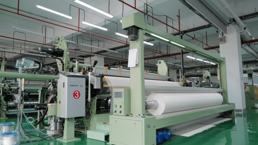
Industrial filter cloth production for filter press dewatering systems
In nickel-cobalt hydrometallurgy production, filter cloth cleaning and maintenance must be incorporated into standardized operational management. Stable and regular cloth cleaning can effectively prevent gradual deterioration of filtration cycle parameters. Frequent equipment shutdowns for manual cloth cleaning will increase labor costs and production downtime, turning the filtration unit from a process optimization link into a production bottleneck.
Vertical vs. Conventional Filter Presses: Model Selection for MHP Projects
Vertical filter presses adapt to high-automation MHP production scenarios
Vertical filter presses are the preferred solution for MHP projects that require compact plant layout, fully automated operation, stable material washing and repeatable cycle control. Most hydrometallurgical plants favor vertical structures for their ability to reduce manual intervention and support long-term continuous and standardized production operations.
Nevertheless, vertical filter presses are not a universal solution for all scenarios. The final selection needs to be comprehensively evaluated based on slurry test data, design processing capacity, on-site space constraints, automation budget, daily maintenance conditions and operator technical proficiency. While vertical equipment delivers superior process control, it must be matched with the project’s slurry characteristics and operational mode to exert optimal performance.
Conventional filter presses retain unique application value
Traditional chamber filter presses and membrane filter presses still play an irreplaceable role in various industrial slurry treatment scenarios. They feature simple structural design, convenient daily inspection, low maintenance difficulty and easy operator mastery. For projects with moderate processing capacity, mature maintenance teams and flexible on-site space, conventional filter presses remain a cost-effective and practical choice.
The optimal selection logic is not to pursue the “best” equipment in general terms, but to match equipment performance with project core indicators, including target cake moisture, production cycle efficiency, washing uniformity, automation level, floor space, maintenance accessibility and full-cycle operating costs.
Required Technical Data for Accurate Filter Press Quotation
Complete process parameters avoid mismatched equipment selection
Simple provision of processing capacity and material type cannot support accurate filter press configuration. A complete technical quotation package should cover slurry source, solid content, particle size distribution, pH value, operating temperature, liquid phase chemical composition, target cake moisture, washing process requirements, filtrate quality standards, daily operating hours, on-site installation space and automation configuration preferences.
For MHP production projects, slurry sample testing is particularly critical. Suppliers can formulate targeted equipment solutions and parameter configurations based on actual slurry test data or pilot production data. Although the technical communication cycle is slightly longer, it can effectively avoid equipment selection errors and eliminate major operational risks after project commissioning.
Advance confirmation of on-site working conditions ensures long-term stable operation
Hydrometallurgical production plants feature harsh operating environments, including corrosive media, high humidity, abrasive solid particles, limited equipment operation space and high-load continuous production schedules. In the procurement stage, buyers need to confirm key configurations such as filter plate material, filter cloth adaptability, pipeline and valve materials, washing system design, electrical control cabinet protection grade and spare parts supply guarantee.
Meanwhile, maintenance accessibility must be fully considered. Sufficient operating space is required for daily filter plate inspection, filter cloth replacement, discharge area cleaning and cake removal operations. A cramped installation layout will render technically qualified equipment difficult to operate and maintain, affecting long-term production efficiency.
NHD’s Customized Filtration Solutions for Nickel-Cobalt Hydrometallurgy Projects
In nickel-cobalt hydrometallurgy process chains, filter presses are not standalone post-precipitation equipment, but core units connecting slurry transportation, material washing, filtrate recycling, cake discharge, warehousing transportation and downstream refining processes. The mismatch of any filtration system link will trigger systematic production problems: excessive cake moisture increases material handling pressure, uneven washing reduces product consistency, and unstable filtration cycles disrupt the overall production rhythm.
Different from ordinary equipment manufacturers, NHD (New Hongda) positions itself as a professional chemical engineering solution provider, integrating R&D, design and supply of industrial filtration equipment and complete process systems. The company’s product portfolio covers industrial filter presses, agitators, thickeners, sulfuric acid process equipment, desulfurization equipment, pressure vessels, automatic filter press series and supporting filter cloth products, enabling one-stop customized matching for filtration projects with dual demands of equipment adaptation and process optimization.
For nickel-cobalt hydrometallurgy and MHP dewatering scenarios, NHD’s core recommended product is the vertical automatic pressure filter. This equipment is specially designed for integrated filtration, washing and dewatering processes, with a wide application scope covering non-ferrous metal smelting, titanium dioxide processing, fine chemical industry, coal separation and industrial wastewater treatment. Its rich industrial application experience fully adapts to the complex solid-liquid separation demands of hydrometallurgy projects, which require coordinated control of slurry adaptability, cake moisture, washing precision and operational stability.
NHD’s vertical automatic pressure filter is not a standardized universal product, but a targeted solution for high-standard dewatering scenarios. It delivers core advantages in low-moisture cake output, full-automatic operation, compact floor space and stable repeatable dewatering performance. In MHP production, these advantages effectively solve pain points such as high transportation costs, unstable storage quality, high labor dependence and difficult downstream processing caused by unqualified filter cake. Supported by over 10 years of independent R&D accumulation and multiple technical patents, the equipment provides reliable technical support for project customization and parameter optimization.
Before project confirmation, buyers can provide NHD with complete project data, including slurry source, solid content, particle size, pH value, temperature, liquid composition, target moisture, washing requirements, daily processing capacity, installation space, automation configuration and maintenance conditions. Accurate pre-project parameter matching can avoid post-commissioning risks of qualified equipment operation but unqualified process indicators, effectively reducing project trial and error costs.
To sum up, NHD is not merely a filter press manufacturer for nickel-cobalt hydrometallurgy projects, but a professional solution supplier focused on scenario-based customized filtration matching. Its core value lies in three aspects: precise adaptation to hydrometallurgical slurry characteristics, intelligent and automatic filtration process control, and effective reduction of MHP dewatering instability risks after project commissioning.
FAQ
Q1: What is the core function of filter presses in nickel-cobalt hydrometallurgy?
A1: It performs efficient solid-liquid separation after core processes such as precipitation, material washing and residue treatment. In MHP production lines, it realizes deep dewatering of filter cake, providing qualified raw materials for subsequent warehousing, transportation and refining procedures.
Q2: Why is MHP dewatering more difficult than conventional slurry filtration?
A2: MHP slurry contains a large number of fine particles that easily retain moisture. The final dewatering effect is affected by multiple factors including cake formation state, washing uniformity, pressure response performance and filter cloth adaptability. In addition, short-term small-batch tests cannot fully reflect the cycle stability of long-term industrial production, leading to potential operational risks.
Q3: Is a vertical filter press always the best choice for MHP projects?
A3: Not necessarily. Vertical filter presses excel in scenarios requiring high automation, compact layout and stable washing effects. The final selection must be comprehensively judged based on actual slurry test data, processing capacity demands, moisture targets, maintenance schemes and project budgets.
Q4: What are the main causes of excessive moisture in MHP filter cake?
A4: Common causes include ultra-fine slurry particles, poor cake formation, mismatched filter cloth model, insufficient or fluctuating squeezing pressure, inadequate pressing holding time,
inaccurate washing control, and equipment parameters not matching actual slurry working conditions.
Q5: What technical information needs to be provided for accurate filter press selection?
A5: Buyers need to provide complete parameters including slurry solid content, particle size distribution, pH value, temperature, liquid phase composition, target cake moisture, washing process requirements, daily processing capacity, operating hours, on-site layout and automation demands. Providing slurry samples or pilot test data can further improve the accuracy and reliability of equipment selection.
Civil construction companies play a crucial role in shaping the built environment across Australia. Their expertise spans a wide variety of projects, both public and private, each requiring specific skills, resources, and regulatory compliance. Understanding the types of projects a civil construction firm can deliver helps in appreciating the breadth and value they bring to infrastructure development.
Public sector civil construction projects are funded and commissioned by local, state, or federal government bodies. These initiatives are often large-scale and aimed at improving community infrastructure, safety, and accessibility.
Transport Infrastructure Civil construction firms are extensively involved in building and upgrading roads, highways, bridges, tunnels, and railways. Projects like the WestConnex motorway in Sydney or the Melbourne Metro Tunnel are prime examples of large-scale public investments delivered by civil contractors.
Water and Sewerage Systems Governments frequently engage a civil construction company for the development and maintenance of water supply and wastewater treatment infrastructure. These include dams, pumping stations, pipelines, and desalination plants, all essential for supporting urban and regional populations.
Public Buildings and Facilities While often associated with vertical construction, civil companies may be contracted for the site preparation and structural components of hospitals, schools, airports, and sporting facilities. Civil works can involve everything from earthmoving and grading to laying foundations and drainage systems.
Parks and Recreational Infrastructure Enhancing liveability in urban areas, councils and state governments invest in parks, pathways, and open spaces. Civil construction is responsible for landscaping, storm water management, and pathway construction within these developments.
Private Sector Projects
Private sector civil construction projects are commissioned by businesses, developers, or private individuals. These projects can range in scale and are usually driven by commercial objectives, timelines, and cost-efficiency.
Residential and Commercial Developments Civil contractors prepare land for housing estates, apartment complexes, and commercial premises. Services include bulk earthworks, road access, utility installation, and stormwater management. These foundational services are critical for enabling vertical construction to proceed safely and efficiently.
Industrial Facilities Mines, factories, logistics hubs, and warehouses often require tailored civil solutions. Construction companies in this space may be tasked with building haul roads, laying heavy-duty pavements, or constructing retaining walls and site drainage systems to support heavy machinery and operations.
Renewable Energy Projects With Australia’s growing investment in renewables, civil firms are increasingly engaged in the construction of wind farms, solar arrays, and battery storage facilities. Their role typically involves site levelling, road access creation, and the installation of cable trenches and foundations.
Private Infrastructure Upgrades Large corporations may contract civil contractors to upgrade internal roads, car parks, or underground services on their campuses or facilities, enhancing safety and capacity.
Whether in the public or private sector, civil construction companies provide the backbone for physical infrastructure in Australia. Their ability to deliver diverse projects—from motorways and water treatment plants to industrial access roads and renewable energy infrastructure, makes them indispensable to national development and economic growth. By leveraging engineering know-how, regulatory understanding, and modern construction methods, these companies continue to shape Australia’s future.
Computed Radiography (CR) is a modern non-destructive testing (NDT) technique that replaces film radiography with a digital imaging process. Computed radiography (CR) does not use traditional X-ray films. Instead, it relies on imaging plates (IPs) to capture high-resolution images. These images are then processed digitally. Consequently, this approach enhances inspection speed, defect detection, and overall image quality. Furthermore, the digital processing ability provides more efficient data storage and analysis.
Computed radiography is widely used in NDT inspections for welds, pipelines, castings, and aerospace components. It eliminates the need for chemical film processing, making it a cost-effective, Eco-friendly, and efficient choice. Additionally, computer radiography allows for faster image analysis, easy digital storage, and seamless sharing for better decision-making.
The transition from film radiography to computerized radiography occurs due to its superior accuracy. This shift also results from reduced operational costs and improved safety standards. This article explains what Computed Radiography means and how it works. It highlights its benefits in NDT inspections. These insights help industries adopt advanced digital testing solutions for better reliability and performance.
Computed Radiography (CR) is an advanced non-destructive testing (NDT) technique that replaces film radiography with a digital imaging system. It uses imaging plates (IPs) instead of traditional X-ray films to capture Radiographic images. Unlike conventional techniques, these plates contain photostimulable phosphors, which store X-ray energy and release it as digital signals during scanning. Moreover, Computerized radiography offers high-resolution images, faster processing, and improved defect detection. As a result, it has become widely used in industries like aerospace, oil and gas, and manufacturing.
Computed Radiography Process
The Computed Radiography process involves three key steps:
Imaging Plates (IPs): These reusable plates store X-ray exposure data when exposed to radiation.
Scanning Process: A laser scanner reads the plate, converting the stored X-ray energy into a digital signal.
Digital Image Processing: The signal is transformed into a high-quality digital image that can be analyzed, enhanced, and stored electronically.
Computer radiography is superior to film radiography. It eliminates the need for chemical processing. This makes it a faster, cost-effective, and environmentally friendly solution. CR images can be digitally enhanced, stored, and shared easily, reducing human errors and improving inspection efficiency.
Role of Computed Radiography in NDT
Computed Radiography (CR) plays a vital role in Non-destructive Testing (NDT) by providing high-quality digital imaging for industrial inspections. Moreover, it enhances defect detection, enables real-time assessments, and improves workflow efficiency. As a result, CR has become an essential tool in industries like aerospace, automotive, and infrastructure maintenance. Furthermore, its digital capabilities contribute to better data management and streamlined inspection processes.
Detection of Defects in Welds, Castings, and Pipelines
Computerized Radiography allows for precise identification of cracks, porosity, voids, and inclusions in welds, castings, and pipelines. The high-resolution digital images enhance flaw visibility, ensuring correct defect evaluation. Advanced contrast adjustments and zooming features improve detection capabilities, reducing the risk of structural failures in industrial applications.
Inspection of Aerospace, Automotive, and Structural Components
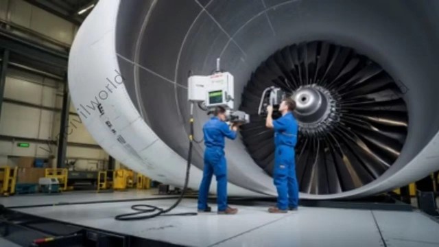
Computed Radiography Process in Aerospace
Computerized Radiography is widely used in aerospace, automotive, and infrastructure industries to inspect critical components without damaging them. It helps assess engine parts, structural frames, and composite materials, ensuring compliance with safety regulations and industry standards. The ability to digitally enhance and analyse images increases inspection reliability.
Evaluation of Corrosion and Material Degradation
Computed radiography is effective in assessing corrosion, thinning, and material degradation in metal structures, pipelines, and storage tanks. The digital imaging process provides detailed insights into material conditions, helping engineers decide maintenance requirements and prevent costly failures. This improves the longevity and reliability of industrial assets.
Advantages in Real-Time and Remote Inspections
Computed Radiography technology enables real-time analysis of scanned images, reducing downtime in critical operations. The ability to store and send images digitally allows for remote assessments, expert consultations, and faster decision-making. This is particularly useful in offshore, hazardous, or hard-to-access locations, improving overall inspection efficiency.
Benefits of Computed Radiography in Inspection Services
Computed Radiography (CR) revolutionizes Non destructive Testing (NDT) by offering high-resolution digital imaging for defect detection in industrial components. It enhances inspection speed, reduces environmental impact, improves image quality, and enables easy digital storage and sharing. CR provides a cost-effective, efficient, and reliable choice to traditional film radiography.
Defect Detection
Computed Radiography (CR) enhances defect detection by providing high-resolution digital images of welds, castings, and pipelines. It helps find cracks, voids, porosity, corrosion, and inclusions with greater accuracy compared to traditional film radiography. Digital image processing also allows for contrast adjustments and zooming, improving defect visibility for precise evaluation.
Computerised Radiography
Faster Inspections
CR radiography eliminates time-consuming film development by using digital imaging plates (IPs) that are scanned for instant results. This significantly reduces inspection time. It allows for quick decision-making in critical applications. These include pipeline integrity assessments, aerospace inspections, and manufacturing quality control. Faster processing improves workflow efficiency and minimizes downtime in industrial operations.
Eco-Friendly Process
Unlike traditional film radiography, which requires chemical processing and hazardous waste disposal, CR radiography is an eco-friendly solution. It eliminates the use of toxic chemicals, reduces material waste, and lowers environmental impact. The reusable imaging plates (IPs) further contribute to sustainability, making CR an environmentally responsible choice for NDT inspections.
Enhanced Image Quality
Digital CR radiography produces high-contrast, noise-free images with greater dynamic range than traditional film. Advanced image processing tools allow for edge enhancement, contrast adjustments, and noise reduction, improving flaw detection. Inspectors can analyse fine details more effectively. This ensures precise defect evaluation. It also reduces the chances of false positives or missed defects.
Easy Storage & Sharing
CR images are stored in digital formats, eliminating the need for physical film storage. Inspectors can easily retrieve, archive, and share images electronically, allowing for remote analysis and collaboration. Digital storage also enables better documentation, traceability, and compliance with industry standards, improving overall inspection efficiency and record management.
Challenges and Limitations of Computed Radiography
While Computed Radiography (CR) offers many advantages in Non-destructive Testing (NDT), it also presents certain challenges and limitations. These challenges include starting investment costs. Training requirements for operators are also significant. There are sensitivity differences compared to Digital Radiography (DR). Additionally, there is potential for equipment damage and workflow considerations.
Starting Investment Costs for Computed Radiography
Implementing CR systems involves significant initial expenses, encompassing imaging plates, scanners, software, and digital storage solutions. CR reduces ongoing costs linked to film and chemical processing. However, the upfront investment can be substantial. This is particularly true for small and medium-sized enterprises.
Training Requirements for Operators
Transitioning from traditional film-based radiography to CR necessitates specialized training for operators. Skill in digital image acquisition, processing, and interpretation is essential to fully leverage CR’s capabilities. Without adequate training, there is a risk of misinterpreting images or mishandling equipment, compromising inspection quality.
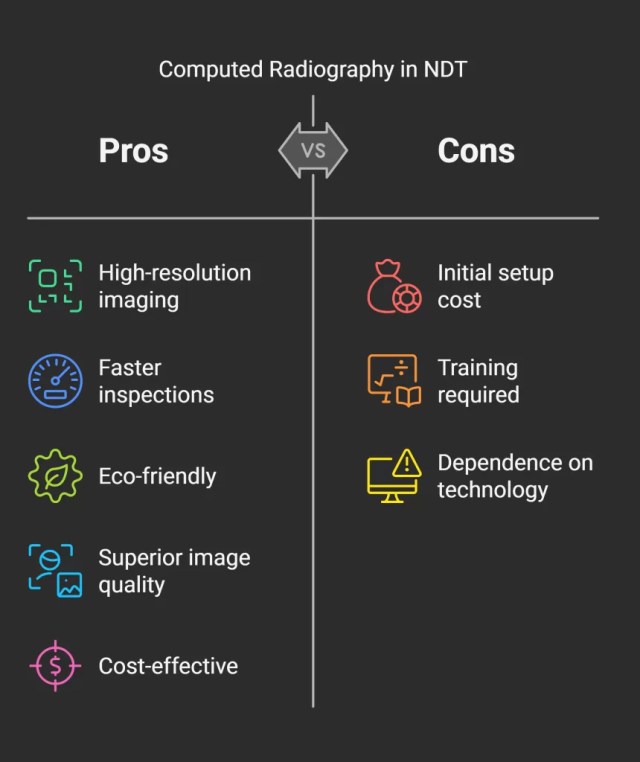
Computed Radiography – Pros and cons
Sensitivity Differences Compared to Digital Radiography (DR)
Computed Radiography systems show lower spatial resolution and sensitivity compared to Digital Radiography systems. This difference can impact the detection of fine defects, making DR more suitable for applications requiring higher precision. Thus, industries with stringent quality standards prefer DR over CR for critical inspections.
Digital Radiography
Potential for Equipment Damage
CR cassettes and imaging plates are susceptible to damage from mishandling or environmental factors. Scratches, exposure to intense light, or physical impacts can degrade image quality or render the plates unusable. Regular maintenance and careful handling are imperative to preserve equipment longevity and guarantee consistent performance.
Workflow Considerations
CR streamlines certain aspects of the imaging process. Nevertheless, it still requires intermediate steps. These include scanning the imaging plates to digitize images. This process can be more time-consuming compared to DR, which offers immediate image acquisition and viewing. In fast-paced environments where time is critical, the extra processing time linked to CR is a limiting factor.
Understanding these challenges is crucial for organizations. It helps them make informed decisions when selecting appropriate Radiographic techniques. This is essential for their specific NDT applications.
Future Trends and Innovations in Computed Radiography
The field of Computed Radiography (CR) is experiencing significant advancements. These advancements are driven by technological innovations and the integration of artificial intelligence (AI). These developments aim to enhance image quality, streamline workflows, and expand the applications of CR in various industries.
Advancements in Imaging Plate Technology in Computed Radiography
Recent progress in imaging plate (IP) technology focuses on improving detector materials and designs to achieve higher resolution and sensitivity. Innovations include the development of direct conversion detectors. These detectors convert X-rays directly into electrical signals. This process reduces noise and enhances image clarity. These advancements allow more precise defect detection in critical applications like aerospace and automotive industries. Additionally, the use of lightweight, portable detectors enhances the flexibility of CR systems. This portability also improves accessibility, facilitating inspections in remote or confined spaces.
Integration with AI for Automated Defect Detection
The integration of AI into CR systems is revolutionizing defect detection by automating image analysis and interpretation. Machine learning algorithms can be trained to identify patterns in Radiographic images. They can also detect anomalies. This improves diagnostic accuracy and reduces the potential for human error. AI-driven tools, such as Generative Adversarial Networks (GANs) and federated learning, enhance defect detection accuracy. They enable secure, collaborative model training across industries. This integration not only accelerates the inspection process. It also facilitates real-time decision-making. This is crucial in industries where safety and reliability are paramount.
Enhanced Resolution and Faster Scanning Techniques
Efforts to enhance resolution have led to the adoption of advanced imaging techniques. Notably, these efforts also aim to speed up scanning processes. For instance, techniques like phase-contrast radiography and hybrid computed tomography (CT) have been developed. As a result, these methods achieve sub-micron resolution and multi-material analysis, allowing for detailed inspections of complex components. Furthermore, the development of portable systems and autonomous robots equipped with AI and quantum X-ray technology is revolutionizing on-site efficiency. As a result, this advancement paves the way for sub-millisecond defect detection by 2025. Moreover, these innovations are particularly beneficial in infrastructure maintenance. They also aid the manufacturing sector, where rapid and precise inspections are essential.
Imaging Plate technology
In summary, the future of Computed Radiography is being shaped by continuous improvements in imaging plate technology. AI integration is also contributing by automating analysis. Additionally, there is a focus on developing high-resolution, fast-scanning techniques. These advancements aim to enhance the efficacy of non-destructive testing. They ensure higher safety standards. This leads to improved operational efficiency across various industries.
Key Takeaways
Enhanced Defect Detection: Computed Radiography (CR) provides high-resolution digital images. This enables precise identification of internal defects. These include cracks, corrosion, and voids in materials and components.
Operational Efficiency: The digital nature of CR streamlines the inspection process. It eliminates the need for chemical film development. This change reduces inspection times and increases throughput.
Environmental Benefits: By removing the need for chemical processing, CR is more environmentally friendly. Disposable films are also eliminated, offering an alternative to traditional Radiographic methods.
Digital Integration: CR facilitates easy storage, retrieval, and sharing of inspection data, enhancing collaboration and record-keeping within inspection services.
Technological Advancements: Ongoing innovations in imaging plate technology are continually improving the capabilities of CR. Artificial intelligence is also enhancing the applications of CR in nondestructive testing (NDT).
Conclusion
Computed Radiography has significantly transformed non-destructive testing and inspection services. It offers a digital, efficient, and environmentally conscious choice to traditional film-based radiography. Its ability to deliver high-quality images expedites defect detection and analysis. This process enhances the reliability and safety of critical components across various industries. The shift towards digital solutions not only streamlines workflows but also aligns with modern environmental standards by reducing chemical waste. As technology progresses, CR will continue to improve. Advancements in imaging plate design and artificial intelligence integration will play a key role. They will offer even greater accuracy and efficiency. Embracing these digital innovations is essential for industries. They need to maintain rigorous quality control and safety standards. This is crucial in an increasingly competitive and environmentally conscious market.
Shrinkage of concrete refers to the reduction in its volume over time, primarily due to moisture loss and chemical reactions during hydration. This phenomenon can lead to shrinkage cracking of concrete, compromising structural integrity and durability. Understanding what shrinkage of concrete is involves recognizing its various forms, such as drying shrinkage, autogenous shrinkage, and thermal shrinkage. Drying shrinkage occurs as moisture evaporates from the hardened concrete. Autogenous shrinkage results from internal chemical reactions during the hydration process. Thermal shrinkage happens due to temperature variations affecting the concrete mass. Factors influencing shrinkage include water-cement ratio, environmental conditions, and the concrete mix design. Mitigating shrinkage involves proper curing practices. It includes using shrinkage-reducing admixtures. Another method is optimizing mix proportions to minimize water content, thereby reducing the potential for shrinkage cracking.
Concrete shrinkage is a critical phenomenon in the construction industry. It refers to the reduction in volume of concrete as it undergoes hydration and drying. This dimensional change can lead to cracking, compromising the structural integrity and durability of concrete structures. Engineers, contractors, and stakeholders must understand the causes, types, and preventive measures of concrete shrinkage. This knowledge ensures the longevity and performance of concrete infrastructures. This article is about the types, causes and effects of Concrete shrinkage
Concrete, a composite material composed of cement,aggregates, water, and admixtures, is the backbone of modern construction. Its versatility, strength, and durability make it the material of choice for various structural applications. However, one inherent characteristic of concrete is its tendency to shrink during the curing process. This shrinkage, if not properly managed, can lead to cracks, reducing the lifespan and safety of structures. Therefore, a comprehensive understanding of concrete shrinkage is paramount for effective construction practices.
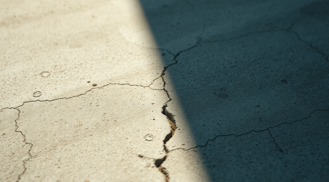
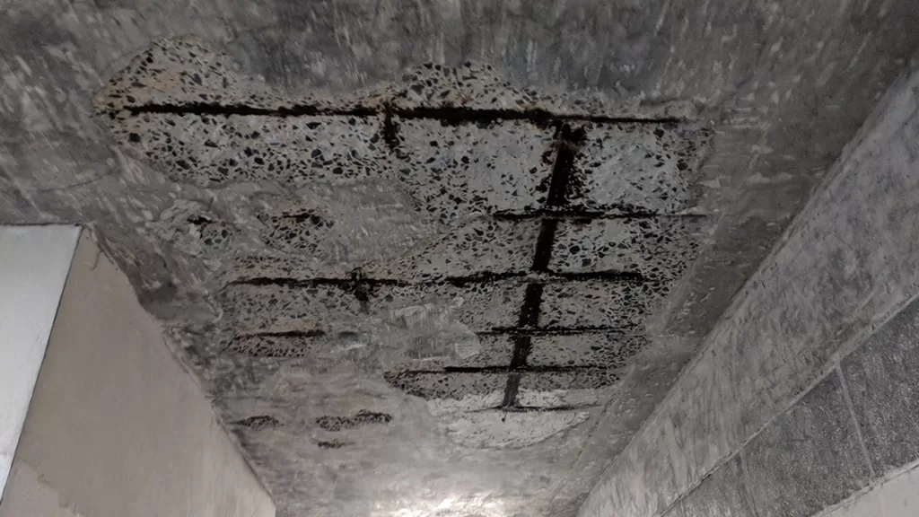
Shrinkage in concrete is the decrease in its volume over time. This occurs due to the loss of moisture and the chemical reactions during cement hydration. This volumetric reduction can induce tensile stresses within the concrete matrix. It leads to the formation of cracks, especially when the material is restrained. Cracks are also likely when shrinkage occurs unevenly. The primary factors influencing concrete shrinkage include the water-cement ratio, environmental conditions, and the properties of the constituent materials.
Types of Concrete Shrinkage
Concrete shrinkage is a natural phenomenon that affects the durability and structural integrity of concrete over time. It occurs due to moisture loss, chemical reactions, or temperature changes, leading to volume reduction and potential cracking. Understanding the different types of shrinkage is crucial. These types include plastic, drying, autogenous, thermal, and carbonation shrinkage. This knowledge helps in selecting appropriate construction techniques. These techniques minimize shrinkage-related issues and improve concrete performance.
Plastic Shrinkage
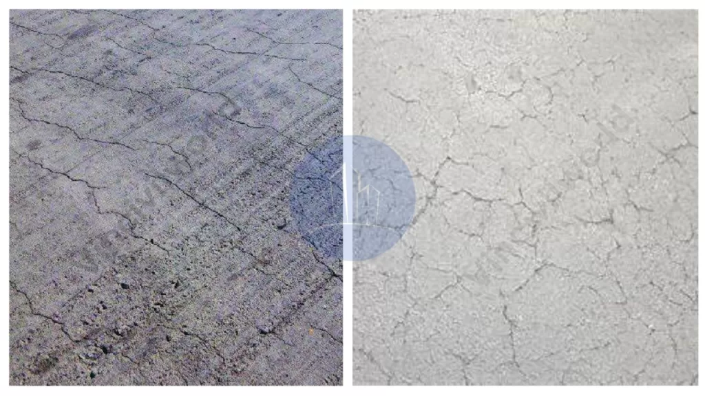
Plastic shrinkage occurs within the first few hours after concrete placement while it is still in a plastic state. It happens due to rapid evaporation of surface moisture, especially in hot, dry, or windy conditions. This leads to surface tension, causing shrinkage cracks to form. These cracks are often random, shallow, and irregular, primarily appearing on slabs and pavements. Preventing plastic shrinkage involves proper curing, windbreaks, shading, and using evaporation retarders to maintain surface moisture and reduce crack formation.
Plastic shrinkage
Drying Shrinkage
Drying shrinkage occurs as hardened concrete loses moisture to the surrounding environment. This process can last months or even years, depending on humidity levels and concrete properties. As water evaporates, capillary tension develops, causing the concrete to contract, leading to shrinkage cracks. These cracks can compromise durability and structural integrity. To reduce drying shrinkage, engineers use shrinkage-reducing admixtures, proper curing methods, and well-graded aggregates. These methods enhance moisture retention and minimize excessive volume reduction.
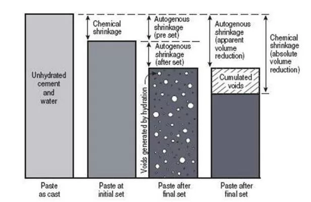
Autogenous shrinkage is common in high-strength, low water-cement ratio concretes where internal chemical reactions drive volume reduction. Unlike drying shrinkage, it occurs without external moisture loss and results from cement hydration reactions consuming water within the concrete. This type of shrinkage is more pronounced in self-consolidating and high-performance concretes, where fine particles create dense microstructures. To mitigate autogenous shrinkage, internal curing techniques are applied. Techniques such as using lightweight aggregates or superabsorbent polymers help retain water for extended hydration.
Thermal shrinkage is caused by temperature variations during the early curing stages of concrete. Cement hydration generates excess heat, causing the concrete to expand. As it cools, the contraction leads to thermal stress and shrinkage cracks. Large structures, such as bridges and massive foundations, are particularly vulnerable to this effect. To control thermal shrinkage, low-heat cement manages heat dissipation. Temperature-controlled pouring also assists. Insulation methods minimize volume changes, preventing long-term structural issues.
Carbonation Shrinkage
Carbonation shrinkage occurs when carbon dioxide (CO₂) from the atmosphere reacts with calcium hydroxide in concrete to form calcium carbonate. This process slightly reduces concrete volume over time and primarily affects thin concrete sections exposed to high CO₂ levels. Although carbonation can increase surface strength, excessive shrinkage can cause microcracking. To limit carbonation shrinkage, proper curing, protective coatings, and low-permeability mixes help slow down CO₂ penetration and maintain durability.
Several factors contribute to concrete shrinkage, and understanding these is crucial for implementing effective preventive measures:
Water Content: Excessive water in the concrete mix increases the potential for shrinkage. Maintaining appropriate water-cement ratios is critical to reducing this risk.
Cement Composition: The type and amount of cement influence shrinkage. High cement content can lead to increased shrinkage due to greater heat of hydration.
Environmental Conditions: High temperatures, low humidity, and wind can accelerate moisture evaporation, leading to increased shrinkage.
Improper Curing: Inadequate curing can result in rapid moisture loss, causing shrinkage and cracking.
Aggregate Properties: The size, type, and grading of aggregates affect the overall shrinkage
Effects of Concrete Shrinkage
Shrinkage can have several detrimental effects on structures:
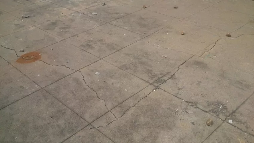
Cracking: As concrete shrinks, tensile stresses develop, leading to cracks, especially if the concrete is restrained.
Reduced Durability: Cracks allow ingress of harmful substances like water and chlorides, which can lead to reinforcement corrosion and reduced lifespan of the structure.
Structural Weakness: Significant shrinkage and cracking can compromise the load-bearing capacity of concrete elements.
How to Reduce Shrinkage in Concrete
To reduce shrinkage and its adverse effects, consider the following measures:
Use Low Water-Cement Ratio: Reducing the amount of water in the mix decreases the potential for shrinkage. However, this must be balanced with workability requirements.
Use of Shrinkage-Reducing Admixtures: Incorporating admixtures can help reduce drying shrinkage and control crack widths.
Optimized Mix Design: Selecting appropriate types and proportions of cement and aggregates can influence shrinkage characteristics.
Environmental Control: Protecting concrete from extreme weather conditions, such as high temperatures and winds, can prevent rapid moisture loss.
Key Takeaways
Definition: The volume reduction due to moisture loss and hydration reactions.
Types: Includes plastic, drying, autogenous, thermal, and carbonation shrinkage.
Influencing Factors: Water-cement ratio, environmental conditions, and material properties.
Mitigation: Proper curing, shrinkage-reducing admixtures, and optimized mix designs are essential.
Importance: Effective shrinkage management preserves structural integrity, enhances durability, and ensures sustainable construction practices.
FAQs
What is concrete shrinkage?
It is the reduction in volume of concrete over time due to moisture loss and chemical reactions during cement hydration.
What causes this?
What are the types of concrete shrinkage?
The primary types include plastic, drying, autogenous, thermal, and carbonation shrinkage.
How can Concrete shrinkage be minimized?
What effects does concrete structures?
Shrinkage can cause cracking, reduce durability, and compromise the structural integrity and load-bearing capacity of concrete elements.
Conclusion
Concrete shrinkage involves a reduction in volume over time due to moisture loss. It also results from chemical reactions during hydration. This phenomenon poses a significant challenge for construction professionals. This blog has explored its various forms, including plastic, drying, autogenous, thermal, and carbonation shrinkage. The blog also examined the factors influencing shrinkage, such as water-cement ratio, environmental conditions, and material properties. Effective mitigation through proper curing, shrinkage-reducing admixtures, and optimized mix designs is crucial to prevent cracking and preserve structural integrity. By understanding these dynamics, engineers, contractors, and stakeholders can implement strategies that enhance durability and safety. Proactive management extends the lifespan of concrete structures. It also contributes to more resilient and sustainable construction practices. Ultimately, diligent control of shrinkage secures long-term performance and trust.
Slipform shuttering is a continuous construction method. In this method, concrete is poured into a continuously moving formwork. This allows for the seamless creation of vertical structures. This technique, known as slipforming, enables the efficient construction of tall edifices such as silos, chimneys, and core walls in high-rise buildings. By employing slipform formwork, builders can achieve monolithic structures without horizontal joints. This method enhances the overall strength and durability of the construction.
The slipform formwork construction process involves the gradual and steady upward movement of the formwork system. This movement is synchronized with the setting rate of the concrete. This ensures that as the formwork ascends, the concrete below has gained sufficient strength to support itself. The continuous nature of slipform shuttering not only accelerates the construction timeline but also reduces labor costs and minimizes the need for scaffolding, making it a preferred choice for large-scale vertical constructions.
The blog will explore the definition and principles of Slipform shuttering, its key components, and the process of slipforming. We will highlight its advantages, common applications, and critical considerations for effective use. Additionally, we will discuss how Slipform formwork construction enhances efficiency and provide insights into best practices for successful implementation.
Slipform shuttering is an advanced construction technique. It enables the continuous pouring of concrete for vertical structures like silos, chimneys, and high-rise cores. The method employs slipform formwork construction, where the formwork system moves steadily upward, synchronized with the concrete’s setting time. This ensures seamless, monolithic structures without horizontal joints.
Significance and Development
The development of slipforming revolutionized construction by enhancing efficiency and reducing project timelines. This method eliminates the need for scaffolding, minimizes labor costs, and ensures structural integrity. Slipform shuttering has become integral in modern construction. It is especially useful for projects requiring tall, uniform structures. This is due to its ability to streamline processes while maintaining high-quality results.
Slipform formwork construction
The slipform formwork construction method basically rely on the following factors
Slipform formwork construction
Continuous Pouring and Synchronized Upward Movement
In slipform shuttering, concrete is poured continuously into a moving formwork system, which climbs steadily as the concrete sets. This synchronized upward movement ensures a seamless structure, eliminating horizontal joints and enhancing strength.
Importance of Concrete Setting Time
The climbing speed of the formwork is carefully calibrated to match the concrete’s setting time. If the formwork ascends too quickly, the concrete may deform due to insufficient strength. Conversely, if it moves too slowly, delays and uneven surfaces can occur. Maintaining this balance is crucial for structural integrity and efficiency. Proper synchronization is essential. It ensures that the concrete beneath the formwork gains enough strength to support its weight. It also needs to withstand construction loads during the process.
Historical Development of Slipform formwork construction
Slipforming has a rich history dating back to the early 20th century. The first slipform systems were primarily used for concrete roads and canals. Over the years, significant technological advancements have led to the development of sophisticated slipform systems that can handle complex structures and challenging environments. Some key milestones in the development of slipforming include:
Early 20th Century: The first rudimentary slipform systems were used for road and canal construction.
Mid-20th Century: The introduction of hydraulic systems and improved concrete technology paved the way for more efficient and versatile slipform systems.
Late 20th Century: The development of computer-controlled slipform systems further enhanced precision and accuracy.
21st Century: Continued advancements in automation, robotics, and material science are leading to even more sophisticated and sustainable slipform systems.
Key components of slipform system
In slipform shuttering, several key components work together to facilitate continuous concrete construction:
Formwork Panels: These vertical molds shape the concrete as it’s poured, ensuring the desired dimensions and surface finish. As the formwork ascends, the panels move upward at a controlled rate, allowing the structure to rise seamlessly.
Jacking Systems: Hydraulic or pneumatic jacks lift the formwork incrementally. They support the formwork, platforms, crew, and withstand the hydrostatic pressure of the fresh concrete. The placement of jacks depends on vertical forces and lateral pressures, ensuring stability during the slipforming process.
Working Platforms: These platforms provide safe and accessible areas for workers to perform tasks such as pouring concrete, monitoring alignment, and managing reinforcement. They move in tandem with the formwork, maintaining consistent working conditions.
Support Structures: Elements like yokes and whalers distribute loads from the formwork and jacking systems, maintaining structural integrity. Yokes connect the formwork to the jacks, while whalers reinforce the formwork panels, ensuring even pressure distribution.
Concrete Placement Equipment: Conveying systems like concrete pumps or chutes ensure continuous concrete delivery to the formwork.
Vibration System: Compacts the concrete within the formwork, eliminating air pockets and ensuring a uniform density.
The cohesive interaction of these components enables the efficient construction of vertical structures. These structures are continuous and without joints. This process enhances both speed and structural integrity.
Types of slipform shuttering
Slipform shuttering encompasses several types, each tailored to specific construction needs. The most common types of slipform shuttering types are as follows
Vertical slipform shuttering
Horizontal Slipform shuttering
Tapered slipform
Conical slipform
Egg shaped slipform
Cantilever type
Vertical Slipform
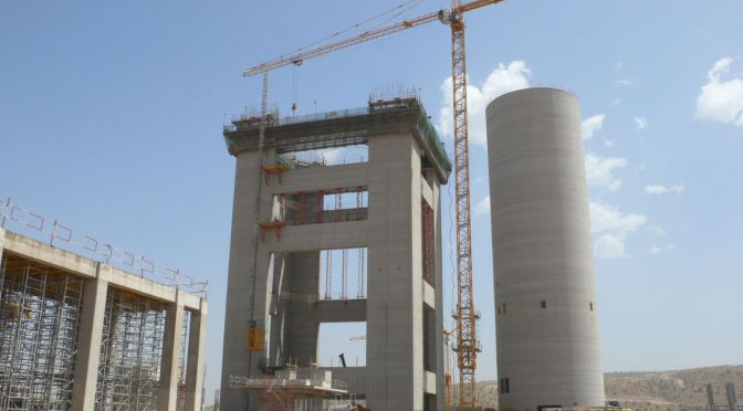
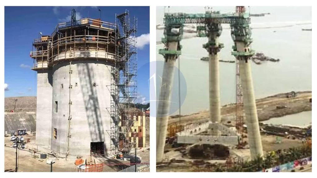
Builders use vertical slipform to construct tall structures, such as silos, chimneys, or towers. They employ a moving formwork system that continuously ascends as they pour concrete. Workers gradually raise the formwork using hydraulic jacks, ensuring a smooth and consistent construction process.This method allows for the creation of vertical concrete structures without the need for scaffolding or traditional formwork systems. As the concrete sets, the formwork slips upwards, maintaining a uniform shape. Vertical slipform is efficient for projects requiring rapid construction, offering enhanced safety and reduced labor costs. It also ensures high-quality finishes and precise dimensions, making it suitable for large-scale industrial and infrastructure projects.
Slipform shuttering /slipforming
Horizontal Slipform shuttering
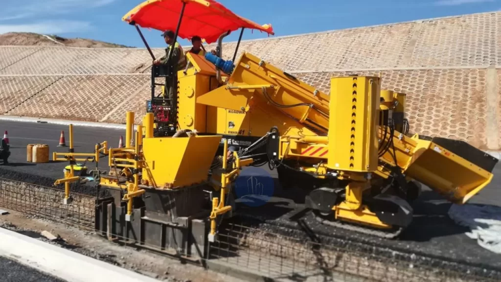
This technique is utilized in constructing horizontal structures such as road pavements and bridge decks. It allows the formwork to move horizontally. This movement enables continuous concrete placement along the structure’s length. Workers use horizontal slipform to create continuous concrete elements such as pavements, curbs, drainage channels, and safety barriers. This method involves the extrusion of concrete in situ, allowing for uninterrupted casting of long sections.
A specially designed machine has a mold with the required dimensions. It is equipped with vibrators for concrete compaction and moves forward at a controlled rate. The machine powers itself and mounts on wheels or tracks, ensuring stability during operation. As workers pour concrete from the rear of the machine, it becomes self-supporting. The machine follows a prefixed guide wire to achieve the correct line and level. This approach offers advantages such as speed, the ability to produce monolithic structures, and operational economy.
Horizontal slipform formwork construction
Tapered Slipform shuttering
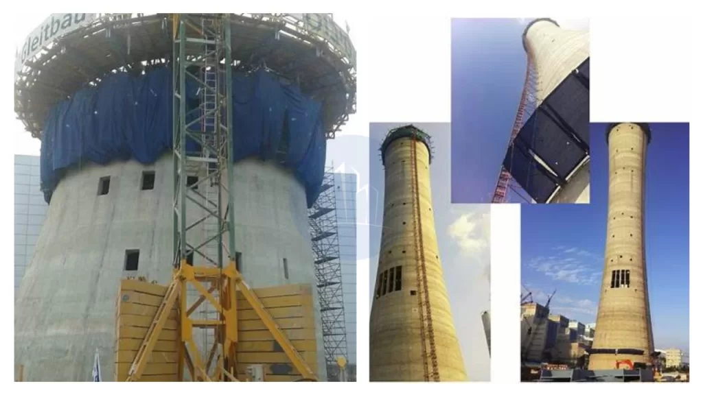
This method is designed for structures with varying cross-sections, such as conical chimneys and cooling towers. It adjusts the formwork dimensions during the slipforming process. This adjustment achieves the desired tapering effect.
Builders use tapered slipform to create structures with a gradually narrowing shape. Examples include chimneys, cooling towers, and tall industrial structures. They employ movable formwork that adjusts in size as it rises, allowing for a tapered design. Similar to vertical slipform, workers pour concrete continuously as the formwork rises, typically using hydraulic jacks or other lifting mechanisms. Engineers design the formwork carefully to accommodate the structure’s changing cross-section, ensuring a precise and smooth taper.This method offers efficiency in construction, as it reduces the need for complex scaffolding and allows for a seamless, uniform finish. Tapered slipform is ideal for projects requiring strong, stable, and visually appealing tapered structures.
Tapered construction
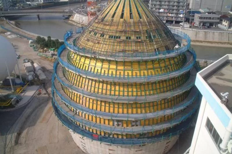
Conical Slipform shuttering
Builders use conical slipform to construct structures with a conical shape, such as cooling towers or silos. They use a moving formwork that continuously ascends as workers pour concrete. Workers shape the formwork to create a gradual narrowing toward the top. This process forms the cone. Workers raise the formwork using hydraulic jacks or other lifting mechanisms as the concrete cures, ensuring a smooth and consistent structure. This approach is highly efficient, as it eliminates the need for scaffolding and enables continuous, uninterrupted pouring. Conical slipform offers precise control over the shape and finish. It is ideal for large-scale, high-strength structures with conical geometry. It also reduces labor costs and construction time.
Egg-shaped Slipform
Engineers use egg-shaped slipform to create structures with an elliptical or egg-like shape. These structures include certain types of silos, industrial towers, and water or wastewater treatment facilities. They utilize specially designed formwork that moves vertically as workers pour concrete continuously. The formwork is shaped to create the unique, rounded profile of the egg shape, gradually narrowing at the top. Workers raise the formwork using hydraulic jacks or other lifting mechanisms, ensuring smooth and consistent construction. Egg-shaped slipform provides benefits like efficient construction with minimal labor, reduced material waste, and precise control over the shape. This technique is particularly suitable for structures requiring unique, aerodynamic designs, offering both functional and aesthetic advantages.
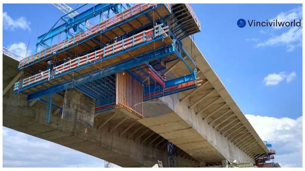
This method enables builders to construct structures that extend horizontally beyond their supports. These structures include certain bridge segments. It also allows them to build overhanging elements without the need for additional support scaffolding.
In cantilever slipform, construction teams use a method to build structures with an overhanging or projecting shape, such as bridges, dams, and tall towers. They gradually move the formwork system upwards while pouring concrete continuously. The structure itself supports the formwork, which extends outward as it rises, creating a cantilever effect. This technique is ideal for projects where workers have limited access to both sides of the structure or when constructing from the top down. Cantilever slipform ensures a precise and smooth finish, with high structural integrity. It reduces the need for scaffolding or external supports, making it an efficient and cost-effective method for large-scale projects that require overhanging sections or complex geometries.
Cantilever slipforming
Engineers design each type of slipform shuttering to meet specific architectural and structural demands, enhancing construction efficiency and quality.
Advantages of Slipform Formwork Construction
Slipform shuttering offers several advantages in construction, making it a preferred method for certain types of structures. Some key benefits include:
Speed and Efficiency: Continuous pouring and raising of formwork allow for faster construction, reducing overall project timelines.
Cost-Effective: It minimizes labor costs by eliminating the need for scaffolding and extensive formwork, resulting in a more economical process.
High Quality: The method provides a smooth, consistent finish with high precision and uniformity in dimensions.
Safety: With less reliance on manual labor and scaffolding, slipform offers enhanced safety for workers during construction.
Minimal Material Wastage: The continuous nature of the process reduces material waste, making it more environmentally friendly.
Reduced Need for Supervision: Automated or semi-automated systems reduce the need for constant supervision, leading to better management of resources.
Versatility: Suitable for a variety of structures, including vertical, tapered, conical, and curved shapes, making it adaptable to different project requirements.
Monolithic Structures: Slipform allows for the construction of monolithic concrete elements, improving the structural integrity of the finished project.
Durability: The seamless construction process ensures strong, durable structures with fewer weak points.
Reduced Labor Dependency: The method relies on machinery, reducing the need for large labor forces and improving construction consistency.
Challenges and disadvantages of Slipform Shuttering
While slipforming offers numerous advantages, it also presents several challenges that need to be carefully managed to ensure successful implementation.
High Initial Setup Costs: The machinery, formwork, and equipment required for slipforming can be costly. This leads to high upfront investments. Such investments may not be feasible for smaller projects.
Complexity in Design: Formwork design must be highly precise and adaptable to varying shapes and sizes. Skilled engineering and planning are necessary to meet specific project requirements.
Skilled Labor: Skilled operators are crucial for proper alignment. They ensure smooth operation. The availability of experienced personnel is essential for effective slipforming.
Concrete Quality Control: Maintaining consistency in concrete mix and quality is vital. Any variation in material quality, mix ratios, or curing methods can negatively impact the structure’s integrity.
Weather Conditions: Unfavorable weather, such as heavy rain or freezing temperatures, can disrupt the slipforming process. It can also affect concrete curing. This necessitates careful planning and adjustments.
Continuous Supervision: Despite automation, slipforming systems still require constant monitoring to address potential malfunctions or adjustments during the process.
Site Access: Limited access to construction sites can make it challenging to transport the necessary machinery and materials.
By addressing these challenges with proper planning, slipforming can be an efficient construction method. Skilled labor and risk management also contribute to its effectiveness.
Applications of Slipform shuttering
Slipform shuttering is a versatile construction technique. It is employed across various industries for its efficiency. It also has the ability to create continuous, seamless structures. Key applications include:
High-Rise Building Cores: Slipform is ideal for constructing the core walls of high-rise buildings. It enables rapid and uniform construction of elevator shafts and stairwells.
Chimneys and Cooling Towers: The method is extensively used for building tall, tapered structures like chimneys and cooling towers. It ensures consistent quality and structural integrity.
Silos and Tanks: Slipform facilitates the construction of large storage silos and tanks. It provides a cost-effective and efficient solution for industries requiring bulk storage.
Bridges: Bridge piers and abutments benefit from slipform construction, allowing for continuous pouring and reducing the need for formwork stripping.
Roadways and Pavements: In highway construction, slipform is used to build continuous pavements, curbs, and barriers. This technique enhances construction speed. It also improves surface uniformity.
Dams: Slipform technology is applied in constructing concrete-faced dams, enabling efficient and continuous pouring of concrete.
Water Towers: The technique is employed to construct the walls of water towers, ensuring uniformity and structural strength.
Offshore Structures: Slipform is utilized in the construction of offshore platforms and structures, providing a robust and continuous concrete shell.
These applications highlight the versatility and efficiency of slipform shuttering in modern construction projects.
Advancements in slipform construction
Advancements in automation and real-time monitoring have significantly enhanced slipform shuttering processes. Integrating automated systems with real-time concrete monitoring allows for precise adjustments during construction, ensuring optimal curing conditions and structural integrity. By embedding sensors within the concrete, teams can monitor parameters like temperature and strength, enabling timely interventions and reducing delays.
Additionally, innovations in materials and formwork technology have improved efficiency and safety. Modern formwork systems are designed to be cost-effective, lightweight, reusable, and easy to assemble and dismantle. These advancements contribute to faster construction times and enhanced structural performance.
Collectively, these developments modernize construction practices by increasing efficiency, reducing costs, and ensuring higher-quality outcomes.
Conclusion
Slipform shuttering has revolutionized modern construction by enabling continuous, efficient, and precise building of complex structures. Its key benefits include faster construction timelines and reduced labor costs. It also minimizes material wastage and improves safety by eliminating the need for scaffolding. The method ensures a smooth, uniform finish. It is highly adaptable to various structural shapes. These include high-rise cores, chimneys, silos, cooling towers, bridges, and dams. It is particularly effective for projects requiring repetitive, large-scale concrete pouring. Slipform shuttering reduces manual labor. It optimizes resource use and modernizes construction practices. These improvements make construction practices more cost-effective, environmentally friendly, and precise. Its efficiency and scalability are crucial for meeting the demands of large infrastructure projects in today’s fast-paced construction industry.













 vin civilworld