Tag Archives: health

Filter Press Solutions for Nickel-Cobalt Hydrometallurgy Projects

Most failures and operational bottlenecks in nickel-cobalt hydrometallurgy projects stem not from drastic, obvious equipment faults, but from cumulative minor filtration issues. Common onsite challenges include overly moist MHP filter cake that hinders transportation, fluctuating filtration cycle stability, inconsistent slurry properties across production batches, premature filter cloth blinding, and downstream process stagnation caused by dewatering efficiency failing to keep up with precipitation output.

On the surface, filter press procurement appears to be a straightforward equipment sourcing task. Standard purchasing workflows typically involve buyers specifying basic filter press demands and suppliers quoting prices based on processing capacity. However, this simplified matching method is far from sufficient for nickel-cobalt hydrometallurgy scenarios. Professional filter press selection for such projects requires full alignment with actual working conditions, including slurry characteristics, material washing requirements, target cake moisture, on-site corrosion environment, automation configuration demands and plant layout constraints.

Neglecting these key process parameters may result in operational equipment, yet failing to meet project expectations in terms of operating costs, final cake moisture indicators and long-term production stability.

  1. Why Does Filtration Become a Bottleneck in Nickel-Cobalt Projects?
    1. Slurry properties dynamically change across process stages
    2. Excessively moist filter cake triggers cascading operational costs
  2. Why Is MHP Dewatering More Challenging Than Conventional Slurry Filtration?
    1. MHP production requires dual control of moisture stability and washing consistency
    2. Fine particles increase cycle time control difficulty
  3. Key Verification Items for Filter Press Selection
    1. Prioritize slurry parameter data over equipment sizing
    2. Set practical and business-aligned cake moisture targets
  4. Influence of Filter Press Design on Cake Moisture and Operational Stability
    1. Optimized plate structure and precise pressure control are core guarantees
    2. Filter cloth selection determines long-term operational efficiency
  5. Vertical vs. Conventional Filter Presses: Model Selection for MHP Projects
    1. Vertical filter presses adapt to high-automation MHP production scenarios
    2. Conventional filter presses retain unique application value
  6. Required Technical Data for Accurate Filter Press Quotation
    1. Complete process parameters avoid mismatched equipment selection
    2. Advance confirmation of on-site working conditions ensures long-term stable operation
  7. NHD’s Customized Filtration Solutions for Nickel-Cobalt Hydrometallurgy Projects
  8. FAQ

Why Does Filtration Become a Bottleneck in Nickel-Cobalt Projects?

Slurry properties dynamically change across process stages

The nickel-cobalt hydrometallurgy process covers core working procedures including leaching, solution purification, precipitation, material washing and solid-liquid dewatering. Each processing stage alters the physical and chemical properties of the raw material. Before the slurry enters the filter press unit, key indicators such as solid content, particle size distribution, pH value, temperature, fluid viscosity and impurity concentration will undergo continuous changes.

This fundamental difference means nickel-cobalt solid-liquid separation cannot be equated with conventional wastewater filtration. Fine solid particles in the slurry will slow down filtrate drainage speed, while viscous precipitates tend to trap residual moisture. In addition, acidic or alkaline slurry environments will cause corrosion and wear on filter cloths, filter plates, piping and valve components. When project procurement only focuses on hourly processing capacity while ignoring variable slurry characteristics, the selected filter press may meet theoretical design parameters on paper but encounter frequent operational problems during continuous industrial production.

Excessively moist filter cake triggers cascading operational costs

For most nickel-cobalt hydrometallurgy projects, especially MHP (mixed hydroxide precipitate) production lines, filter cake moisture is not merely a technical indicator. It directly governs the whole-chain costs and operational efficiency of subsequent material handling, warehousing, packaging and transportation, and even increases the energy consumption and reprocessing pressure of downstream drying procedures. A slight increase in cake moisture content will lead to more transportation trips, heavier warehouse storage load and unstable material supply rhythms for downstream processes.

Against this backdrop, most project operators prioritize low-moisture MHP cake dewatering solutions. The core demand is not simply to obtain dry filter cake, but to eliminate hidden operational costs and production risks caused by unstable dewatering performance.

Why Is MHP Dewatering More Challenging Than Conventional Slurry Filtration?

MHP production requires dual control of moisture stability and washing consistency

As a critical intermediate product in nickel-cobalt smelting and hydrometallurgy processes, MHP requires systematic washing and deep dewatering after precipitation, before final warehousing, outbound transportation or further refining processing. Accordingly, high-performance filter presses for MHP production need to achieve more than basic solid-liquid separation. They must deliver stable low-moisture filter cake, qualified impurity removal effects and consistent cake discharge performance in every production cycle.

Uneven material washing will lead to residual soluble impurities in the filter cake; insufficient squeezing pressure or inaccurate cycle parameter control will result in excessive cake moisture; unstable cake discharge will force operators to spend extra time cleaning filter plates and filter cloths. These defects are usually not obvious in short-term laboratory tests but will gradually evolve into prominent production problems during long-term continuous operation.

Fine particles increase cycle time control difficulty

Slurries generated from MHP production and nickel laterite processing contain a large number of fine particles, which inherently hinder rapid filtrate drainage. It is common for filter presses to achieve the target cake moisture in laboratory small-batch tests, yet fail to match the cycle time required for industrial-scale daily production. This creates a practical operational dilemma: the filter cake quality is up to standard, but the overall line throughput cannot meet production targets.

For project investors and operators, the core evaluation criterion for filter press selection is not merely “whether the equipment can produce dry cake”, but “whether the equipment can stably reach the target moisture while matching the cycle time required for normal plant production”.

Key Verification Items for Filter Press Selection

Prioritize slurry parameter data over equipment sizing

Most mismatched filter press selections originate from incomplete and inaccurate process parameter data. Filtration area and nominal processing capacity alone cannot support precise equipment model selection. Before configuring filter press systems for nickel laterite and MHP production projects, buyers must sort out complete on-site process parameters.

The core reference data includes slurry solid content, particle size distribution, pH value, operating temperature, liquid phase composition, target filter cake moisture, filtrate clarity requirements, material washing process standards, daily processing capacity and annual operating hours. If the project has completed pilot tests, all pilot slurry test data should be fully provided to suppliers; if the process formula is still in the optimization stage, relevant adjustment information should also be communicated in a timely manner.

In short, filter press selection cannot rely solely on tonnage indicators. The core basis lies in the actual performance of specific slurry in cake formation, filtrate seepage, pressure response and post-washing molding.

Set practical and business-aligned cake moisture targets

Reducing filter cake moisture is a universal demand for hydrometallurgy projects, but blindly pursuing ultra-low moisture indicators will trigger a series of performance trade-offs. Increasing squeezing pressure, extending holding time, thickening filter cake thickness or replacing high-precision filter cloths can effectively lower moisture content, but may simultaneously prolong production cycles, accelerate filter cloth wear, raise energy consumption and increase daily maintenance costs.

For nickel-cobalt projects, cake moisture targets must be formulated based on actual business demands, whether to reduce transportation costs, optimize warehouse storage conditions, stabilize downstream feeding or lower drying energy consumption. Clarifying the core application goal enables targeted selection of filter presses with matched performance, avoiding inefficient parameter adjustment driven by the vague goal of “pursuing the driest possible cake”.

Influence of Filter Press Design on Cake Moisture and Operational Stability

Optimized plate structure and precise pressure control are core guarantees

The overall performance of a filter press is determined by multiple core components including filter chamber structure, filter plate material, feeding system, hydraulic drive unit and pressure control system. For complex hydrometallurgical slurries, the equipment must maintain stable pressure output, uniform slurry filling and reliable sealing performance. Uneven feeding will cause inconsistent cake thickness and quality; poor sealing will lead to slurry leakage and material loss; imprecise hydraulic control will result in fluctuating squeezing effects and unstable moisture indicators.

In high-standard MHP deep dewatering scenarios, membrane squeezing technology is usually adopted to further reduce cake moisture and improve cake discharge fluency. However, the application of membrane squeezing must match the slurry’s compressibility characteristics and production cycle requirements. The adaptation effect varies for different slurries, so targeted slurry tests are essential before final equipment confirmation.

Filter cloth selection determines long-term operational efficiency

Although filter cloths are classified as consumable parts, their model selection and matching directly decide the long-term stable operation of the entire filtration system. Key indicators including cloth permeability, material corrosion resistance, weaving structure and daily cleaningmethods all affect filtration efficiency and service life. A filter cloth with excellent initial drainage performance may suffer rapid blinding when facing slurries containing ultra-fine particles; while high-retention filter cloths can improve filtrate clarity, they often reduce drainage rate and extend cycle time.
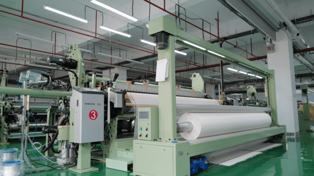
Industrial filter cloth production for filter press dewatering systems

In nickel-cobalt hydrometallurgy production, filter cloth cleaning and maintenance must be incorporated into standardized operational management. Stable and regular cloth cleaning can effectively prevent gradual deterioration of filtration cycle parameters. Frequent equipment shutdowns for manual cloth cleaning will increase labor costs and production downtime, turning the filtration unit from a process optimization link into a production bottleneck.

Vertical vs. Conventional Filter Presses: Model Selection for MHP Projects

Vertical filter presses adapt to high-automation MHP production scenarios

Vertical filter presses are the preferred solution for MHP projects that require compact plant layout, fully automated operation, stable material washing and repeatable cycle control. Most hydrometallurgical plants favor vertical structures for their ability to reduce manual intervention and support long-term continuous and standardized production operations.

Nevertheless, vertical filter presses are not a universal solution for all scenarios. The final selection needs to be comprehensively evaluated based on slurry test data, design processing capacity, on-site space constraints, automation budget, daily maintenance conditions and operator technical proficiency. While vertical equipment delivers superior process control, it must be matched with the project’s slurry characteristics and operational mode to exert optimal performance.

Conventional filter presses retain unique application value

Traditional chamber filter presses and membrane filter presses still play an irreplaceable role in various industrial slurry treatment scenarios. They feature simple structural design, convenient daily inspection, low maintenance difficulty and easy operator mastery. For projects with moderate processing capacity, mature maintenance teams and flexible on-site space, conventional filter presses remain a cost-effective and practical choice.

The optimal selection logic is not to pursue the “best” equipment in general terms, but to match equipment performance with project core indicators, including target cake moisture, production cycle efficiency, washing uniformity, automation level, floor space, maintenance accessibility and full-cycle operating costs.

Required Technical Data for Accurate Filter Press Quotation

Complete process parameters avoid mismatched equipment selection

Simple provision of processing capacity and material type cannot support accurate filter press configuration. A complete technical quotation package should cover slurry source, solid content, particle size distribution, pH value, operating temperature, liquid phase chemical composition, target cake moisture, washing process requirements, filtrate quality standards, daily operating hours, on-site installation space and automation configuration preferences.

For MHP production projects, slurry sample testing is particularly critical. Suppliers can formulate targeted equipment solutions and parameter configurations based on actual slurry test data or pilot production data. Although the technical communication cycle is slightly longer, it can effectively avoid equipment selection errors and eliminate major operational risks after project commissioning.

Advance confirmation of on-site working conditions ensures long-term stable operation

Hydrometallurgical production plants feature harsh operating environments, including corrosive media, high humidity, abrasive solid particles, limited equipment operation space and high-load continuous production schedules. In the procurement stage, buyers need to confirm key configurations such as filter plate material, filter cloth adaptability, pipeline and valve materials, washing system design, electrical control cabinet protection grade and spare parts supply guarantee.

Meanwhile, maintenance accessibility must be fully considered. Sufficient operating space is required for daily filter plate inspection, filter cloth replacement, discharge area cleaning and cake removal operations. A cramped installation layout will render technically qualified equipment difficult to operate and maintain, affecting long-term production efficiency.

NHD’s Customized Filtration Solutions for Nickel-Cobalt Hydrometallurgy Projects

In nickel-cobalt hydrometallurgy process chains, filter presses are not standalone post-precipitation equipment, but core units connecting slurry transportation, material washing, filtrate recycling, cake discharge, warehousing transportation and downstream refining processes. The mismatch of any filtration system link will trigger systematic production problems: excessive cake moisture increases material handling pressure, uneven washing reduces product consistency, and unstable filtration cycles disrupt the overall production rhythm.

Different from ordinary equipment manufacturers, NHD (New Hongda) positions itself as a professional chemical engineering solution provider, integrating R&D, design and supply of industrial filtration equipment and complete process systems. The company’s product portfolio covers industrial filter presses, agitators, thickeners, sulfuric acid process equipment, desulfurization equipment, pressure vessels, automatic filter press series and supporting filter cloth products, enabling one-stop customized matching for filtration projects with dual demands of equipment adaptation and process optimization.

For nickel-cobalt hydrometallurgy and MHP dewatering scenarios, NHD’s core recommended product is the vertical automatic pressure filter. This equipment is specially designed for integrated filtration, washing and dewatering processes, with a wide application scope covering non-ferrous metal smelting, titanium dioxide processing, fine chemical industry, coal separation and industrial wastewater treatment. Its rich industrial application experience fully adapts to the complex solid-liquid separation demands of hydrometallurgy projects, which require coordinated control of slurry adaptability, cake moisture, washing precision and operational stability.

NHD’s vertical automatic pressure filter is not a standardized universal product, but a targeted solution for high-standard dewatering scenarios. It delivers core advantages in low-moisture cake output, full-automatic operation, compact floor space and stable repeatable dewatering performance. In MHP production, these advantages effectively solve pain points such as high transportation costs, unstable storage quality, high labor dependence and difficult downstream processing caused by unqualified filter cake. Supported by over 10 years of independent R&D accumulation and multiple technical patents, the equipment provides reliable technical support for project customization and parameter optimization.

Before project confirmation, buyers can provide NHD with complete project data, including slurry source, solid content, particle size, pH value, temperature, liquid composition, target moisture, washing requirements, daily processing capacity, installation space, automation configuration and maintenance conditions. Accurate pre-project parameter matching can avoid post-commissioning risks of qualified equipment operation but unqualified process indicators, effectively reducing project trial and error costs.

To sum up, NHD is not merely a filter press manufacturer for nickel-cobalt hydrometallurgy projects, but a professional solution supplier focused on scenario-based customized filtration matching. Its core value lies in three aspects: precise adaptation to hydrometallurgical slurry characteristics, intelligent and automatic filtration process control, and effective reduction of MHP dewatering instability risks after project commissioning.

FAQ

Q1: What is the core function of filter presses in nickel-cobalt hydrometallurgy?

A1: It performs efficient solid-liquid separation after core processes such as precipitation, material washing and residue treatment. In MHP production lines, it realizes deep dewatering of filter cake, providing qualified raw materials for subsequent warehousing, transportation and refining procedures.

Q2: Why is MHP dewatering more difficult than conventional slurry filtration?

A2: MHP slurry contains a large number of fine particles that easily retain moisture. The final dewatering effect is affected by multiple factors including cake formation state, washing uniformity, pressure response performance and filter cloth adaptability. In addition, short-term small-batch tests cannot fully reflect the cycle stability of long-term industrial production, leading to potential operational risks.

Q3: Is a vertical filter press always the best choice for MHP projects?

A3: Not necessarily. Vertical filter presses excel in scenarios requiring high automation, compact layout and stable washing effects. The final selection must be comprehensively judged based on actual slurry test data, processing capacity demands, moisture targets, maintenance schemes and project budgets.

Q4: What are the main causes of excessive moisture in MHP filter cake?

A4: Common causes include ultra-fine slurry particles, poor cake formation, mismatched filter cloth model, insufficient or fluctuating squeezing pressure, inadequate pressing holding time,

inaccurate washing control, and equipment parameters not matching actual slurry working conditions.

Q5: What technical information needs to be provided for accurate filter press selection?

A5: Buyers need to provide complete parameters including slurry solid content, particle size distribution, pH value, temperature, liquid phase composition, target cake moisture, washing process requirements, daily processing capacity, operating hours, on-site layout and automation demands. Providing slurry samples or pilot test data can further improve the accuracy and reliability of equipment selection.


Shrinkage of concrete – Effects and Mitigation Strategies

Shrinkage of concrete refers to the reduction in its volume over time, primarily due to moisture loss and chemical reactions during hydration. This phenomenon can lead to shrinkage cracking of concrete, compromising structural integrity and durability. Understanding what shrinkage of concrete is involves recognizing its various forms, such as drying shrinkage, autogenous shrinkage, and thermal shrinkage. Drying shrinkage occurs as moisture evaporates from the hardened concrete. Autogenous shrinkage results from internal chemical reactions during the hydration process. Thermal shrinkage happens due to temperature variations affecting the concrete mass. Factors influencing shrinkage include water-cement ratio, environmental conditions, and the concrete mix design. Mitigating shrinkage involves proper curing practices. It includes using shrinkage-reducing admixtures. Another method is optimizing mix proportions to minimize water content, thereby reducing the potential for shrinkage cracking.

Concrete shrinkage is a critical phenomenon in the construction industry. It refers to the reduction in volume of concrete as it undergoes hydration and drying. This dimensional change can lead to cracking, compromising the structural integrity and durability of concrete structures. Engineers, contractors, and stakeholders must understand the causes, types, and preventive measures of concrete shrinkage. This knowledge ensures the longevity and performance of concrete infrastructures. This article is about the types, causes and effects of Concrete shrinkage

  1. What is shrinkage of concrete ?
  2. Types of Concrete Shrinkage
    1. Plastic Shrinkage
    2. Drying Shrinkage
    3. Autogenous Shrinkage
    4. Thermal Shrinkage
    5. Carbonation Shrinkage
  3. Causes of Shrinkage in Concrete
  4. Effects of Concrete Shrinkage
  5. How to Reduce Shrinkage in Concrete
  6. Key Takeaways
  7. FAQs
  8. Conclusion

What is shrinkage of concrete ?

Concrete, a composite material composed of cement, aggregates, water, and admixtures, is the backbone of modern construction. Its versatility, strength, and durability make it the material of choice for various structural applications. However, one inherent characteristic of concrete is its tendency to shrink during the curing process. This shrinkage, if not properly managed, can lead to cracks, reducing the lifespan and safety of structures. Therefore, a comprehensive understanding of concrete shrinkage is paramount for effective construction practices.

Shrinkage in concrete is the decrease in its volume over time. This occurs due to the loss of moisture and the chemical reactions during cement hydration. This volumetric reduction can induce tensile stresses within the concrete matrix. It leads to the formation of cracks, especially when the material is restrained. Cracks are also likely when shrinkage occurs unevenly. The primary factors influencing concrete shrinkage include the water-cement ratio, environmental conditions, and the properties of the constituent materials.

Types of Concrete Shrinkage

Concrete shrinkage is a natural phenomenon that affects the durability and structural integrity of concrete over time. It occurs due to moisture loss, chemical reactions, or temperature changes, leading to volume reduction and potential cracking. Understanding the different types of shrinkage is crucial. These types include plastic, drying, autogenous, thermal, and carbonation shrinkage. This knowledge helps in selecting appropriate construction techniques. These techniques minimize shrinkage-related issues and improve concrete performance.

Plastic Shrinkage

Plastic shrinkage occurs within the first few hours after concrete placement while it is still in a plastic state. It happens due to rapid evaporation of surface moisture, especially in hot, dry, or windy conditions. This leads to surface tension, causing shrinkage cracks to form. These cracks are often random, shallow, and irregular, primarily appearing on slabs and pavements. Preventing plastic shrinkage involves proper curing, windbreaks, shading, and using evaporation retarders to maintain surface moisture and reduce crack formation.

Plastic shrinkage of concrete
Plastic shrinkage

Drying Shrinkage

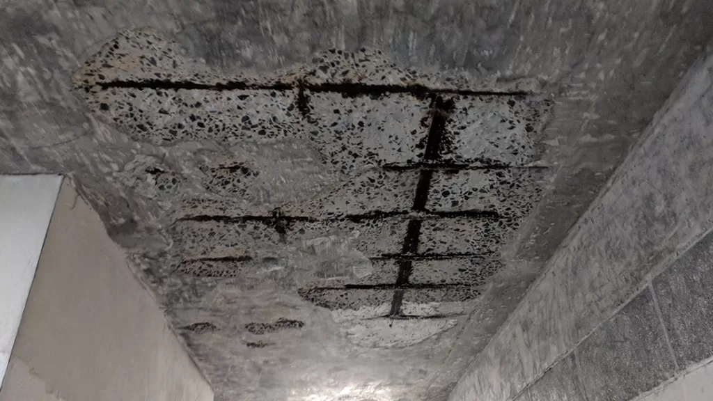
Drying shrinkage occurs as hardened concrete loses moisture to the surrounding environment. This process can last months or even years, depending on humidity levels and concrete properties. As water evaporates, capillary tension develops, causing the concrete to contract, leading to shrinkage cracks. These cracks can compromise durability and structural integrity. To reduce drying shrinkage, engineers use shrinkage-reducing admixtures, proper curing methods, and well-graded aggregates. These methods enhance moisture retention and minimize excessive volume reduction.

Drying shrinkage of concrete
Drying Shrinkage (Image Source: ResearchGate)

Autogenous Shrinkage

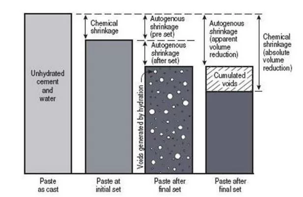
Autogenous shrinkage is common in high-strength, low water-cement ratio concretes where internal chemical reactions drive volume reduction. Unlike drying shrinkage, it occurs without external moisture loss and results from cement hydration reactions consuming water within the concrete. This type of shrinkage is more pronounced in self-consolidating and high-performance concretes, where fine particles create dense microstructures. To mitigate autogenous shrinkage, internal curing techniques are applied. Techniques such as using lightweight aggregates or superabsorbent polymers help retain water for extended hydration.

Autogenous Shrinkage
Autogenous shrinkage (Image Source: ResearchGate)

Thermal Shrinkage

Thermal shrinkage is caused by temperature variations during the early curing stages of concrete. Cement hydration generates excess heat, causing the concrete to expand. As it cools, the contraction leads to thermal stress and shrinkage cracks. Large structures, such as bridges and massive foundations, are particularly vulnerable to this effect. To control thermal shrinkage, low-heat cement manages heat dissipation. Temperature-controlled pouring also assists. Insulation methods minimize volume changes, preventing long-term structural issues.

Thermal

Carbonation Shrinkage

Carbonation shrinkage occurs when carbon dioxide (CO₂) from the atmosphere reacts with calcium hydroxide in concrete to form calcium carbonate. This process slightly reduces concrete volume over time and primarily affects thin concrete sections exposed to high CO₂ levels. Although carbonation can increase surface strength, excessive shrinkage can cause microcracking. To limit carbonation shrinkage, proper curing, protective coatings, and low-permeability mixes help slow down CO₂ penetration and maintain durability.

Carbonation shrinkage
Carbonation Shrinkage : Structural Guide

Causes of Shrinkage in Concrete

Several factors contribute to concrete shrinkage, and understanding these is crucial for implementing effective preventive measures:

  • Water Content: Excessive water in the concrete mix increases the potential for shrinkage. Maintaining appropriate water-cement ratios is critical to reducing this risk.
  • Cement Composition: The type and amount of cement influence shrinkage. High cement content can lead to increased shrinkage due to greater heat of hydration.
  • Environmental Conditions: High temperatures, low humidity, and wind can accelerate moisture evaporation, leading to increased shrinkage.
  • Improper Curing: Inadequate curing can result in rapid moisture loss, causing shrinkage and cracking.
  • Aggregate Properties: The size, type, and grading of aggregates affect the overall shrinkage

Effects of Concrete Shrinkage

Shrinkage can have several detrimental effects on structures:

  • Cracking: As concrete shrinks, tensile stresses develop, leading to cracks, especially if the concrete is restrained.
  • Reduced Durability: Cracks allow ingress of harmful substances like water and chlorides, which can lead to reinforcement corrosion and reduced lifespan of the structure.
  • Structural Weakness: Significant shrinkage and cracking can compromise the load-bearing capacity of concrete elements.

How to Reduce Shrinkage in Concrete

To reduce shrinkage and its adverse effects, consider the following measures:

  • Use Low Water-Cement Ratio: Reducing the amount of water in the mix decreases the potential for shrinkage. However, this must be balanced with workability requirements.
  • Use of Shrinkage-Reducing Admixtures: Incorporating admixtures can help reduce drying shrinkage and control crack widths.
  • Optimized Mix Design: Selecting appropriate types and proportions of cement and aggregates can influence shrinkage characteristics.
  • Environmental Control: Protecting concrete from extreme weather conditions, such as high temperatures and winds, can prevent rapid moisture loss.

Key Takeaways

  1. Definition: The volume reduction due to moisture loss and hydration reactions.
  2. Types: Includes plastic, drying, autogenous, thermal, and carbonation shrinkage.
  3. Influencing Factors: Water-cement ratio, environmental conditions, and material properties.
  4. Mitigation: Proper curing, shrinkage-reducing admixtures, and optimized mix designs are essential.
  5. Importance: Effective shrinkage management preserves structural integrity, enhances durability, and ensures sustainable construction practices.

FAQs

  1. What is concrete shrinkage?
    • It is the reduction in volume of concrete over time due to moisture loss and chemical reactions during cement hydration.
  2. What causes this?
  3. What are the types of concrete shrinkage?
    • The primary types include plastic, drying, autogenous, thermal, and carbonation shrinkage.
  4. How can Concrete shrinkage be minimized?
  5. What effects does concrete structures?
    • Shrinkage can cause cracking, reduce durability, and compromise the structural integrity and load-bearing capacity of concrete elements.

Conclusion

Concrete shrinkage involves a reduction in volume over time due to moisture loss. It also results from chemical reactions during hydration. This phenomenon poses a significant challenge for construction professionals. This blog has explored its various forms, including plastic, drying, autogenous, thermal, and carbonation shrinkage. The blog also examined the factors influencing shrinkage, such as water-cement ratio, environmental conditions, and material properties. Effective mitigation through proper curing, shrinkage-reducing admixtures, and optimized mix designs is crucial to prevent cracking and preserve structural integrity. By understanding these dynamics, engineers, contractors, and stakeholders can implement strategies that enhance durability and safety. Proactive management extends the lifespan of concrete structures. It also contributes to more resilient and sustainable construction practices. Ultimately, diligent control of shrinkage secures long-term performance and trust.

Piping Isometric Drawings and symbols | How to read?

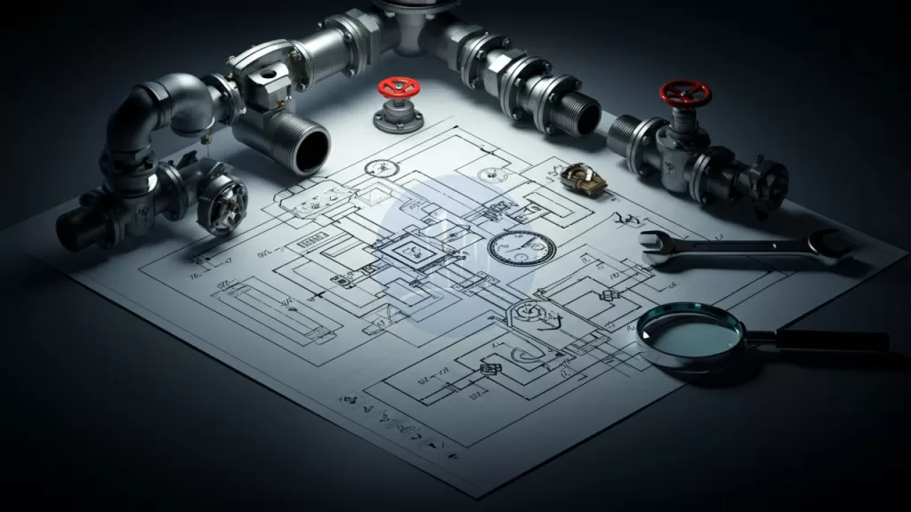
Piping isometric drawings are essential tools in the engineering and construction of pipeline systems. They provide a three-dimensional representation of pipelines in a two-dimensional format, helping engineers visualize complex layouts. Unlike other drawing styles, piping isometric drawings depict the height, width, and depth of the pipeline. This depiction allows for precise planning and communication among project teams. These drawings are critical for pipeline fabrication and ensure that installations align with design specifications.

In this article, we will explore piping isometric drawing symbols. We will also cover isometric pipe drawing symbols and how to read isometric piping drawings. Understanding these symbols and techniques is crucial for accurate and effective pipeline design and construction.

  1. Key Components of Piping Isometric Drawings
  2. Importance of Isometric View in Piping
  3. Piping Isometric Drawing Symbols
  4. How to Read Piping Isometric Drawings
    1. Representation of pipe fittings drawings
    2. Representation of pipe fittings and pipe materials
  5. Representation of pipe fittings in piping isometric drawings
    1. Valve Symbols
    2. Flanges symbols
    3. Instrument Symbols
  6. Applications of Isometric Drawings in Piping Systems
  7. Annotations and Labels in Piping Layout Drawings
  8. Color Code in Piping Systems
  9. Applications of Isometric Drawings in Piping Systems
  10. Steps to Create Isometric Drawings for Piping
  11. Common Challenges in Isometric Piping Drawings
  12. Comparison of Isometric and Orthographic Drawings
  13. Piping Isometric Drawing Standards and Guidelines
  14. Three Main Rules in Isometric Drawing
    1. Key Takeaways: Piping Isometric Drawings and Symbols
  15. Conclusion

Key Components of Piping Isometric Drawings

Piping isometric drawings are crucial in pipeline design, providing 3D representations in a 2D format. They simplify complex layouts, enhance visualization, and ensure accurate fabrication with standardized symbols and clear details.

Piping isometric drawing symbols

Key features of isometric drawings for piping include:

  • A 30-degree angle projection for all axes to show depth.
  • Use of Standardized Symbols: Incorporates symbols for pipes, valves, elbows, and fittings, ensuring consistency and ease of understanding.
  • Precise Dimensions: Includes detailed measurements and angles, aiding accurate fabrication and assembly.
  • Annotations and Notes: Offers material specifications, pipe sizes, welding instructions, and operational details.
  • Flow Direction Indicators: Utilizes arrows and markings to show the flow direction of fluids within the pipeline.
  • Simplified Layout Interpretation: Easier to read compared to other technical drawings, helping teams visualize complex configurations.
  • Fabrication-Friendly Design: Acts as a guide for manufacturers, reducing errors and material wastage.
  • Compliance: Ensures adherence to design and construction standards, supporting effective project execution.
  • Inclusion of key elements such as piping symbols for isometric drawings, directional arrows, and dimension lines.
    These features make isometric drawings of pipelines a preferred choice for complex projects.

Importance of Isometric View in Piping

The isometric view in piping is a visual representation technique. It shows all three dimensions length, width, and height—at equal scales. This unique perspective simplifies complex pipeline layouts, making it easier for engineers to interpret designs accurately. Isometric views provide a clear and comprehensive depiction of the pipeline geometry. This clarity allows engineers to identify potential design challenges or conflicts before construction begins. This visualization method enhances communication among project teams. It ensures that intricate systems are easier to comprehend. This approach ultimately saves time and reduces errors in fabrication and installation processes. The isometric view in piping plays a vital role in streamlining project execution and improving overall design accuracy.

More related posts

Piping Isometric Drawing Symbols

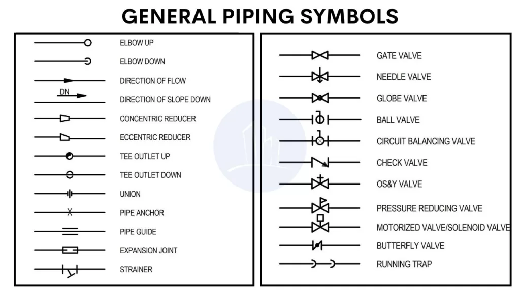
Piping isometric drawing symbols act as a universal language for engineers and fabricators.

Piping isometric drawings represent three-dimensional pipeline systems on a 2D plane. They offer a clear understanding of complex pipe routing across multiple planes. These drawings use single-line representations of pipe centerlines to measure dimensions. They incorporate symbols for components like valves, flanges, reducers, and welds. Common symbols include:

Isometric drawing for piping
  • Valves: Represented by geometric shapes such as circles or rectangles with annotations.
  • Flanges: Depicted as two parallel lines intersecting the pipe.
  • Reducers: Indicated by a tapered line connecting different pipe diameters.
  • Elbows: Shown with angular bends.

How to Read Piping Isometric Drawings

Understanding isometric pipe fittings drawings is crucial when handling complex pipeline systems. These drawings offer a three-dimensional visualization of piping layouts on a two-dimensional surface. They aid engineers, designers, and operators in effective planning and execution. A standard 30-degree angle is applied to the axes, which ensures equal foreshortening of length, width, and height.

This creates a proportional and clear perspective. This approach provides precise information about pipe routes, dimensions, and connection details. It makes it easier to analyze and implement designs. Additionally, it minimizes errors during construction or maintenance. Mastery of isometric pipe fittings drawings enhances efficiency and communication among all stakeholders in pipeline projects.

Representation of pipe fittings drawings

Piping isometric drawings use standardized symbols to represent different pipe fittings and components. These symbols convey critical information about the type, size, and orientation of pipes, valves, and other equipment. Recognizing these symbols is essential for accurately interpreting the layout and functionality of the piping system depicted in the drawing.

Piping isometric drawing symbols

Representation of pipe fittings and pipe materials

Piping isometric drawings specify the material of the pipes, such as carbon steel, stainless steel, copper, or PVC. This information is crucial for understanding the system’s properties and requirements.

In piping isometric drawings, pipes are represented as single lines to simplify the layout. These lines include key information such as pipe size, material, and specification. Arrows indicate flow direction, while symbols represent fittings, valves, and connections. The drawings maintain a 30-degree angle for clarity and accurate visualization.

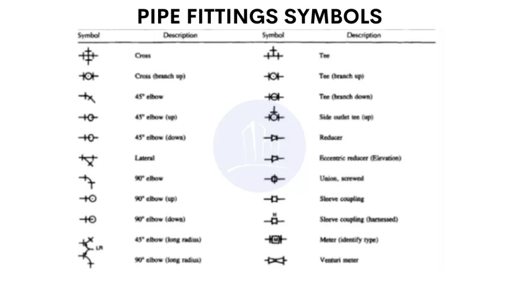
Representation of pipe fittings in piping isometric drawings

Each fitting is represented by a unique symbol on the isometric drawing. This allows you to quickly identify the components. You can also see their orientation within the system.

Pipe fittings drawings

Valve Symbols

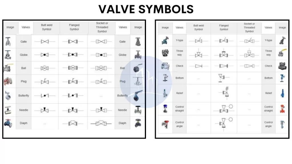
Piping isometric drawings use standardized symbols to represent different types of valves, such as ball, gate, and globe valves. These symbols are typically color-coded to distinguish the valve type.

Pipe fittings drawings
Pipe fittings drawings -Valves

Flanges symbols

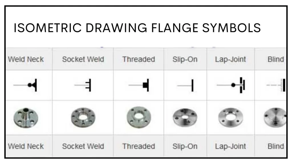
Flange symbols in piping isometric drawings represent the connection points between pipes or pipe and equipment. These symbols vary based on flange type.

Flanges
Piping isometric drawing symbols (Flanges)

Instrument Symbols

Instruments like pressure gauges, thermometers, and flow meters are also depicted using standardized symbols in isometric drawings. These help identify the location and type of instrumentation along the piping system.

Instruments symbols
Instruments

Applications of Isometric Drawings in Piping Systems

Piping layout drawings provide critical information essential for designing and constructing pipeline systems. Here’s what can be obtained from them:

  • Pipe Routing: Exact pathways of pipes, including elevations and orientations.
  • Equipment Locations: Placement of machinery and fixtures in relation to the piping system.
  • Material Specifications: Details about pipe materials, insulation, and coatings.
  • Dimensions: Measurements of pipe lengths, offsets, and distances between components.
  • Fittings and Connections: Types of joints, flanges, and fittings required.
  • Support Systems: Locations and types of pipe supports, hangers, and anchors.
  • Flow Direction: Indicated by arrows to ensure proper operation.
  • Valves and Instruments: Placement and specifications of valves, gauges, and control devices.
  • Safety Features: Emergency shut-off systems and pressure-relief valves.
  • Compliance Data: Adherence to standards, codes, and regulations.

This ensures accuracy and efficiency in pipeline installation and maintenance.

Annotations and Labels in Piping Layout Drawings

  • Pipe Size and Material: Specifies the diameter and material (e.g., steel, PVC) for each pipe, ensuring compatibility.
  • Flow Direction: Uses arrows to indicate the direction of fluid or gas flow within the system.
  • Equipment Tags: Labels machinery and equipment with unique identifiers for easy referencing.
  • Elevation Indicators: Highlights the height or depth of pipes, critical for alignment.
  • Connection Details: Annotates welds, flanges, or threaded connections for assembly.
  • Valve Types and Numbers: Identifies valve locations, types (e.g., gate, globe), and tag numbers for functionality.
  • Support Annotations: Labels pipe supports, hangers, or brackets with their specifications.
  • Insulation and Coating: Notes areas requiring thermal insulation or corrosion-resistant coatings.
  • Instrument Tags: Marks sensors, gauges, and monitoring instruments with unique labels.
  • Safety Instructions: Includes warnings, emergency shutoff points, and safety compliance notes.

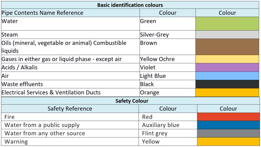
Color Code in Piping Systems

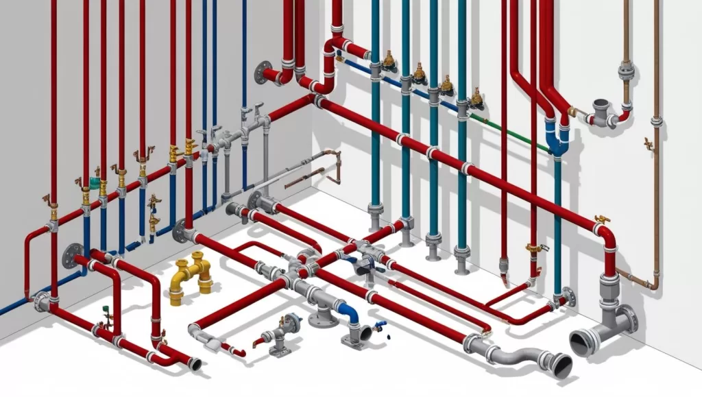
Color coding in piping systems is a standardized method to identify the contents of pipelines for safety and operational efficiency. It aids in quick recognition during maintenance and emergencies.

Piping isometric drawing color codes
color codes
  • Fluid Type Identification: Different colors represent various fluids like water, steam, oil, or gases.
  • Hazard Awareness: Highlights dangerous contents, such as flammable or toxic substances.
  • Directional Arrows: Used alongside color codes to indicate the flow direction.
  • Compliance Standards: Adheres to codes like ANSI/ASME A13.1 or ISO standards for global consistency.
  • Maintenance Assistance: Simplifies troubleshooting by providing instant recognition of pipeline contents and purpose.

A well-read piping isometric drawing minimizes errors in pipeline fabrication and installation.

Applications of Isometric Drawings in Piping Systems

Isometric drawings are vital for designing, installing, and maintaining piping systems, providing comprehensive details about dimensions, layout, and materials in a three-dimensional perspective.

Applications

  1. Design Visualization: Offers a clear 3D view of piping layouts, simplifying complex designs.
  2. Fabrication Guidance: Specifies pipe lengths, angles, and fittings, aiding precise fabrication.
  3. Installation: Guides field teams on accurate pipe placements and alignment.
  4. Material Estimation: Lists materials required for efficient planning and procurement.
  5. Maintenance and Repair: Identifies pipe locations and connections for quick repairs.
  6. Conflict Resolution: Highlights spatial clashes to prevent on-site issues.
  7. Compliance: Ensures designs meet safety and engineering standards.

Steps to Create Isometric Drawings for Piping

Creating isometric drawings for piping involves several key steps to ensure precision. Start by preparing the piping layout, including all components like valves, elbows, tees, and pumps. Set up the isometric grid at the required scale, using a 30-degree angle to represent the three dimensions. Define pipe diameters to mark the size of each pipe accurately. Next, plot the piping components, including pipe runs, fittings, and equipment, using the grid. Add details like material types, flow direction, and any additional specifications. Finally, review and validate the drawing for accuracy, ensuring it aligns with the engineering design.

Various software tools can streamline this process. AutoCAD is great for both 2D and 3D piping designs with isoplane settings. Revit, used in BIM-based designs, generates detailed isometric views and integrates with other data. Tools like SolidWorks, SmartPlant 3D, and MicroStation enhance 3D modeling, offering automation and flexibility for efficient, accurate isometric piping designs.

Common Challenges in Isometric Piping Drawings

Challenges in isometric drawings for pipelines include:

  • Scaling Issues: Misinterpretation of dimensions is common when scaling the drawing. Accurate scaling is crucial to ensure that components fit as designed in the real-world installation.
  • Symbol Miscommunication: Incorrect or inconsistent use of isometric pipe drawing symbols can lead to errors. Adhering to industry standards ensures clarity and prevents confusion during the construction or maintenance stages.
  • Complexity in Detailing: Representing multiple components such as valves, joints, and fittings in a three-dimensional system can be overwhelming, requiring careful attention to maintain accuracy and detail.
  • Alignment and Layout: Improper alignment of pipes and components can disrupt the flow of the design and cause potential installation issues.

Comparison of Isometric and Orthographic Drawings

The Piping isometric drawings and orthographic drawings serve different purposes:

  • Isometric Drawings: Provide a 3D perspective, showing depth, width, and height in a single view, ideal for visualizing complex systems.
  • Orthographic Drawings: Focus on individual planes (top, side, front), giving precise measurements for construction but lacking the 3D perspective.
  • Complex Layouts: Isometric views in piping offer superior clarity and help in understanding the spatial arrangement of components.

Piping Isometric Drawing Standards and Guidelines

International Standards:

  1. ISO 128-30:2017 – This standard outlines the general principles for creating isometric drawings. It includes the use of a 30-degree angle for projections. These projections represent three-dimensional objects on a two-dimensional plane. It ensures uniformity across industries and geographical boundaries.
  2. ASME Y14.5-2009 – The American Society of Mechanical Engineers (ASME) standard provides guidelines on dimensional tolerances, including isometric drawings. It also covers how to represent pipe sizes, materials, and flow directions.
  3. ANSI/ASME B31.3 – This standard for Process Piping explains how isometric drawings should accurately represent the piping system. It includes component layout and material specifications. Additionally, it standardizes symbols for valves, flanges, and fittings.
  4. ISO 5457:2012 – This specifies the size of drawings. It includes the standard sheet size used for isometric drawings. This ensures they are universally recognizable and maintain clarity.

Indian Standards:

  1. IS 696:1972 – The Indian Standard for Engineering Drawing lays the foundation for isometric projections. It also standardizes the use of symbols for different components like valves, elbows, and flanges. It is consistent with international practices in dimensioning and symbol representation.
  2. IS 10701:1983 – This standard applies to the design and drafting of piping systems. It offers specific guidelines for the representation of isometric drawings. It also includes material codes and component alignment.
  3. IS 1235:1982 – This standard focuses on the quality of engineering drawings. It establishes conventions for piping isometric drawings, including scale and symbol usage. These conventions ensure clear communication in the installation and maintenance of piping systems

By adhering to these standards, designers and engineers can create isometric drawings that are clear and standardized. These drawings are easily interpretable across regions and industries.

Three Main Rules in Isometric Drawing

In isometric drawing, three main rules ensure accuracy and clarity:

  1. 30-Degree Angle: The drawing is created using a 30-degree angle to show all three dimensions (length, width, and height) equally foreshortened.
  2. Equal Scaling: All axes should be scaled equally to maintain proportionality and prevent distortion.
  3. Straight Lines: Maintain straight lines for pipes and components, ensuring accurate measurements and preventing confusion.

These rules help in creating precise, easy-to-read representations of three-dimensional systems on a two-dimensional plane.

Key Takeaways: Piping Isometric Drawings and Symbols

  • Essential for Piping: Isometric drawings provide a 3D representation of complex pipeline systems on a 2D plane, showing height, width, and depth for precise planning and communication.
  • Standardized Symbols: These drawings use universally recognized symbols for components like valves, flanges, and fittings, ensuring clarity and consistency in interpretation.
  • Simplified Visualization: The isometric view simplifies complex layouts, aiding engineers and project teams in visualizing and understanding intricate pipeline configurations.
  • Fabrication and Installation Guidance: Precise dimensions, annotations, and material specifications in isometric drawings guide accurate fabrication and installation processes. This reduces errors and ensures compliance with design requirements.
  • Effective Communication: Piping isometric drawings facilitate clear communication among engineers, fabricators, and installers, ensuring accurate execution and minimizing potential conflicts.
  • Standards and Guidelines: Adhering to international and national standards ensures the quality, consistency, and universal interpretability of isometric drawings.

Conclusion

Piping isometric drawings play a critical role in the design, installation, and maintenance of piping systems. Their 3D representation ensures clarity, making complex piping layouts easier to understand and execute. By incorporating standardized symbols for fittings, flanges, and instrumentation, these drawings effectively communicate critical design details. Understanding annotations, color codes, and material representations further enhances their utility. Comparing isometric to orthographic views underscores the unique advantages of each in project execution. Adhering to established standards and guidelines enhances the value of isometric drawings. This adherence ensures precision and efficiency in piping projects across industries. Mastery of these drawings empowers engineers and technicians to streamline workflows, minimize errors, and achieve successful project outcomes.