The penetration test for bitumen is a laboratory method for grading bitumen based on its hardness. In this test, the amount of penetrating a specific needle into the bitumen is measured.
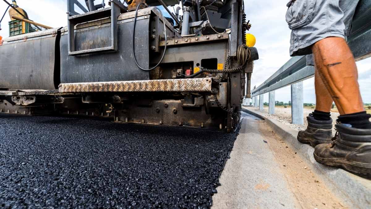
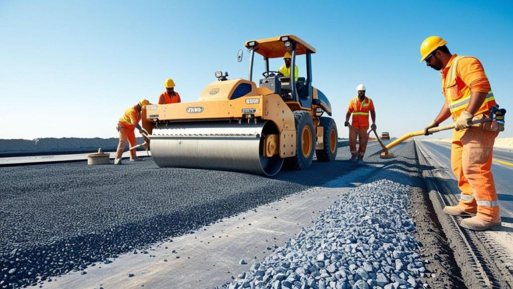
More than 85% of bitumen is used in road construction. Weather condition affects on bitumen binder. In cold weather, bitumen becomes hard, and the possibility of cracking increases. On the other hand, hot weather causes bitumen becomes soft and sticky.
Both situations are not acceptable as a result of civil engineers using penetration tests.
The penetration test for bitumen is a laboratory method for grading bitumen based on its hardness. In this test, the amount of penetrating a specific needle into the bitumen is measured.
This value is reported in a tenth of a millimetre or Deci-millimeter (DMM) as a penetration value. The penetration test can be used for refinery bitumen, emulsion bitumen, and oxidized bitumen. Based on this test bitumen is classified into penetration grades of 20/30, 30/40, 40/50, 50/60, 60/70, and 80/100.
This test can measure the penetration value in the range of 20 to 300 dcmm. It can recognize the bitumen consistency and stability of bitumen.
The first uses of the penetration test, date back to the early 19th century. Before that, the hardness of bitumen is measured based on the Chewing test. It was a completely experienced test. Through that, an engineer chews a moderate-temperature bitumen sample. Then reports the hardness of bitumen according to the difficulty of chewing. Because of the chewing test’s inaccuracy, the penetration test was introduced to the industry.
An overview of the Bitumen Penetration test Importance
More than 85% of bitumen is used in road construction. Weather condition affects on bitumen binder. In cold weather, bitumen becomes hard, and the possibility of cracking increases. On the other hand, hot weather causes bitumen becomes soft and sticky. Both situations are not acceptable as a result of civil engineers using penetration tests.
Bitumen with high penetration values is suitable for cold weather. Because it does not harden and crack when exposed to low temperatures. On other hand, bitumen with smaller penetration values is suitable for hot weather. Because high temperatures can not soften it. Most workable penetration bitumens are penetration grades 60/70 and 80/100. Penetration grade 60/70 can apply to road construction in warm weather and 80/100 is suitable for cold weather.
Bitumen penetration grade 80/100 means that the needle penetrates into the bitumen in the range of 80 to 100 decimeters.
In the following, you can familiarise yourself with the apparatus and the procedure of the test based on ASTM D5. Before that watch the below video by Infinity Galaxy which introduces the penetration test of bitumen.
Apparatus
Penetrometer
Container
Water bath
Stopwatch
Thermometer
Procedure
In the first step, bitumen should be heated up until it becomes liquid. Bitumen should not be heated in a temperature range above 90-100 degrees Celsius otherwise it will burn. While the temperature rises, stir the bitumen to make sure it is uniform. Bitumen should also be free of water and air bubbles.
In the next step, pour the melted bitumen into the container and let it cool at room temperature.
After that put the bitumen container in the water bath with a constant temperature of 25 degrees Celsius and let the sample reach the same temperature.
Then place the container under the penetrometer. Move down the needle just above the bitumen surface.
Thereafter, apply the needle which has a 100gr load just for 5 seconds. Repeat the test 3 times and write down the results each time. The needle tip in each repetition should be apart 10mm from the previous measurements.
Report the mean value as the penetration value of the bitumen sample. The following picture is other important bitumen tests in road construction:
Components of a road or parts of a road plays an important part in ensuring the safety and service life of a road. Components of a road is designed to meet the design requirements, functional requirements etc. This article is about the components of road/parts of a road and its functions.
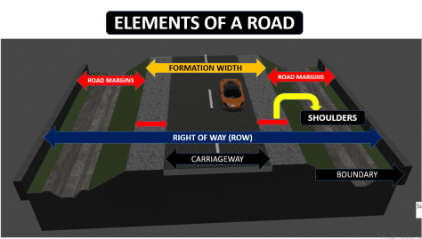
Understanding the road pavement structure is crucial for designing and maintaining effective roadways. Key road components include the carriageway or pavement, roadway or formation width, camber or cross slope, kerbs, medians, road margins, and the right of way (ROW). Each part serves a specific role within the overall road section. This blog will explore these components of the road. It will detail the role of each road section. The blog will explain how they contribute to the road’s durability and performance.
The road components are crucial for ensuring road durability and safety. Each part of the road, from the carriageway to the right of way (ROW), plays a specific role in the road section. Understanding these components and their functions helps in maintaining effective road performance. The main road sections are listed below.
Carriage way or pavement
Road way or formation width
Camber or cross slope
Kerbs
Medians
Road margins
Right of way ( ROW)
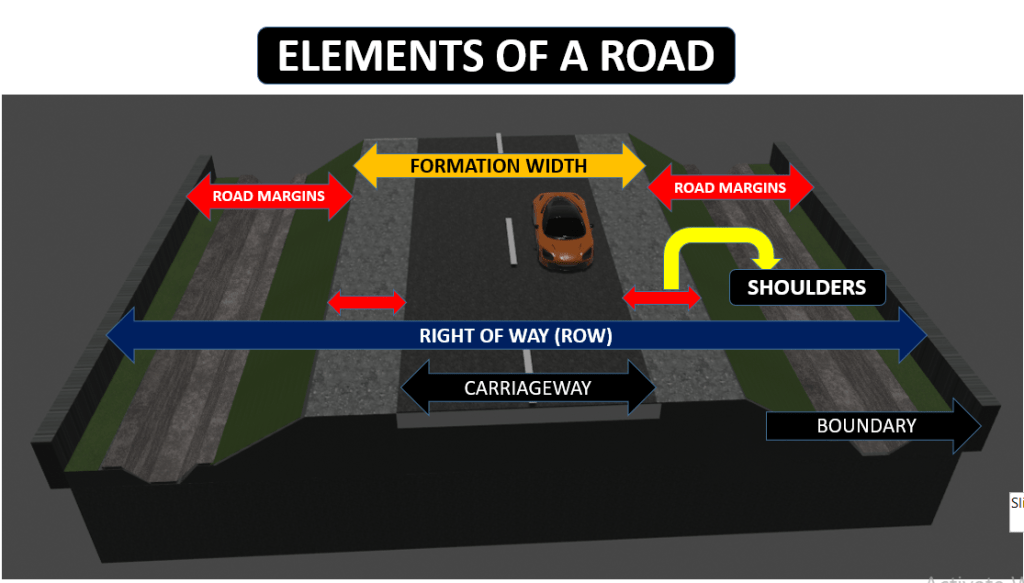
Illustration of the key components of a road, including the carriageway, shoulders, road margins, and right of way.
The paved part or surface of the road for traffic movement without any restriction is called the carriageway. The width of the carriageway/ pavement width depends on the number of traffic lanes. The number of lines is decided based on the type of road, service importance, and traffic density.
The carriageway or pavement width is a critical road component that determines the space available for vehicle movement. It directly affects traffic flow, safety, and overall road performance. Properly designed pavement width ensures efficient use of road space and supports the road’s intended load-bearing capacity.
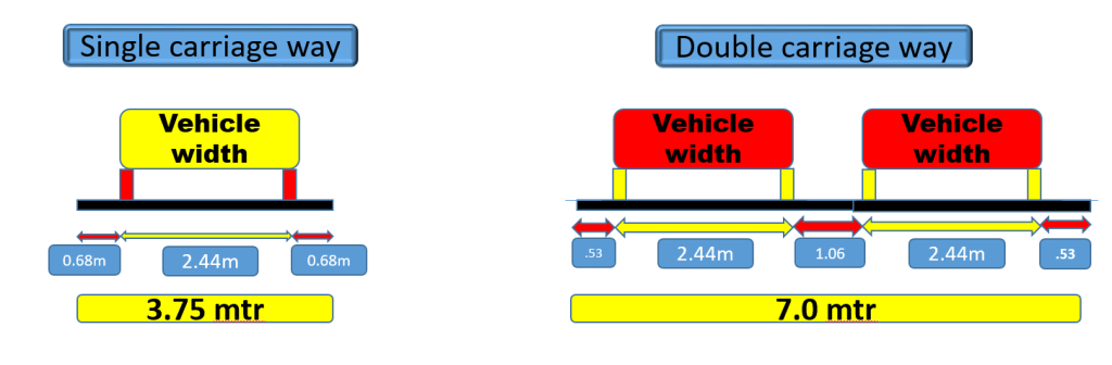
The carriageway is divided into a single carriageway and a dual carriageway as shown in the figure.
Illustration of single and double carriageway road designs, highlighting vehicle width and lane specifications.
The maximum permissible width of a vehicle is 2.44 and the side clearance for single lane traffic is 0.68 m. The required minimum lane width is 3.75 m for a single lane road. For the dual carriageway, the pavement width is two times 3.75 mtr. ie: 7.5 mtr.
Each country has its own specification for carriage way widths.
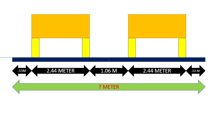
Diagram illustrating the width specifications for dual carriageway design, detailing lane dimensions and spacing.
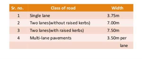
Carriage width as per IRC
Table outlining the width specifications for various classes of roads, including single and multi-lane options.
Road way or formation width
Width of formation or roadway width is the sum of the widths of pavements or carriage way including separators and shoulders. This does not include the extra land in formation/cutting. (Ref : Diagram)
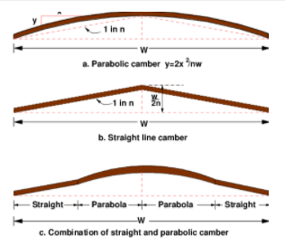
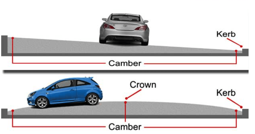
Camber or cross slope
Camber or cross slope provided to raise the middle of the road in the transverse direction to drain of water. Inadequate slopes result in flooding of water on the pavement which may deteriorate the surface in course of time. The too steep slope is undesirable for it will erode the surface.
Illustration of different camber types used in road design, showcasing parabolic and straight line camber techniques essential for effective drainage.
Camber or cross slope serves as Surface protection especially for gravel and bituminous roads. They protect the sub grade by providing proper drainage. This also enables quick drying of pavement. This in turn protects the vehicles from slipping and thereby increases safety.
The value of camber depends on the type of material used for making it and rainfall density in that region.
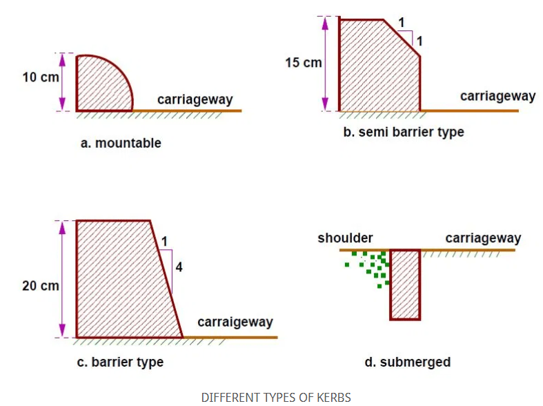
Kerbs
Kerbs are dividing line between carriage way and shoulders, footpath or islands. The following are the different types of kerbs.
Low or mountable kerbs allows the vehicle to enter the shoulder area with little difficultly. Height of 10 cm above pavement level & Edge will have a slope allowing vehicle to step over easily.
Semi barrier type kerbs are used when the pedestrian traffic is high. Their height is 15 cm above the pavement edge. This type of kerb prevents encroachment of parking vehicles. In an acute emergency, it is possible to drive over this kerb with some difficulty.
Barrier type kerbs are designed to discourage vehicles from leaving the pavement.
Illustration of different types of kerbs used in road construction, highlighting their dimensions and functions.
Submerged kerbs are used in rural roads as edges between the pavement edge and shoulders.
Function of kerb
Drainage control
Demarking of walkways
Roadway demarking
Maintenance assistant
Assisting road side development.
Medians or traffic separators
They are physical or painted separation provided to separate two road ways. Mainly used to differentiate vehicles based on speed.
Right of way
Right of way or ROW is the land to be acquired for the road along its alignment. The right of way depends on the importance of the road, traffic an possibility of expansion in the future. They include the total elements of the road like carriageway, shoulders, drainage system, cuttings, and embankment slopes, etc.
Diagram illustrating the essential components of a road including carriageway, shoulders, road margins, formation width, and right of way.
Factors influencing the width of ROW
a) Width of formation
b) Embankment depth and cutting depth
c) Side slopes of embankment or cutting
d) Drainage system
e) site distance considerations
f) Future widening & Service roads.
Road margins
The portion of the road beyond the carriageway and on the roadway can be generally called road margin. Various elements that form the road margins are given below.
Types of rails are mainly divided into three. Double headed rails, bull headed rails and flat footed rails. You will come to know all the important details of each of them with figures in the blog.
In this blog, we’ll explore the various types of rails, offering a detailed look at their unique characteristics and applications. We’ll define rails and delve into the specific types of rail sections. The rail types includes bull headed rails, double headed rails, and flat bottom rails etc. Each rail type will be examined for its design. Their uses and advantages will also be discussed. This will provide you with a comprehensive understanding of these essential components in rail systems.
Rails are an important component of railway tracks. They are high carbon rolled steel sections. These sections are laid end-to-end in two parallel lines over sleepers. This provides a continuous and levelled surface for trains to move. It also helps in carrying axle loads of the rolling stock.
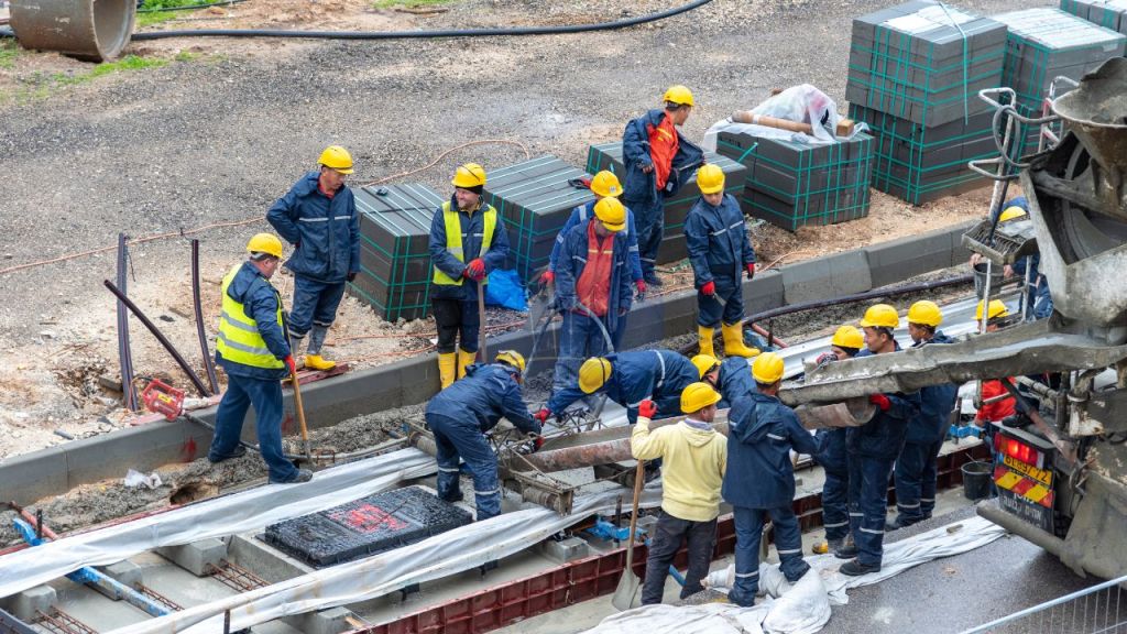
A team of construction workers in safety gear collaborating on a railway construction site.
Rails are essential components in railway systems, providing the track on which trains run. They come in various types of rails, including bull headed rails, double headed rails, and flat bottom rails. Each type serves a specific function, influencing stability and safety. Understanding the types of rail sections helps in selecting the right rails for efficient and reliable rail operations.
Let’s deep into the types of rails.
Main Types of Rails
Types of rails are crucial in rail infrastructure, each designed for specific needs and conditions. Understanding types of rail sections helps in selecting the appropriate rail for various applications. There are mainly 4 types of rails. In this blog, we will explore these 4 key types of rails:
Double Headed Rails
Bull Headed Rails
Flat Bottom Rails
Vignole Rails
Each section will include a detailed figure for clarity.
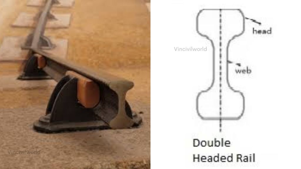
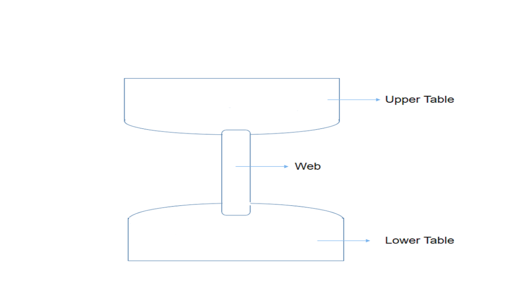
Double headed rails
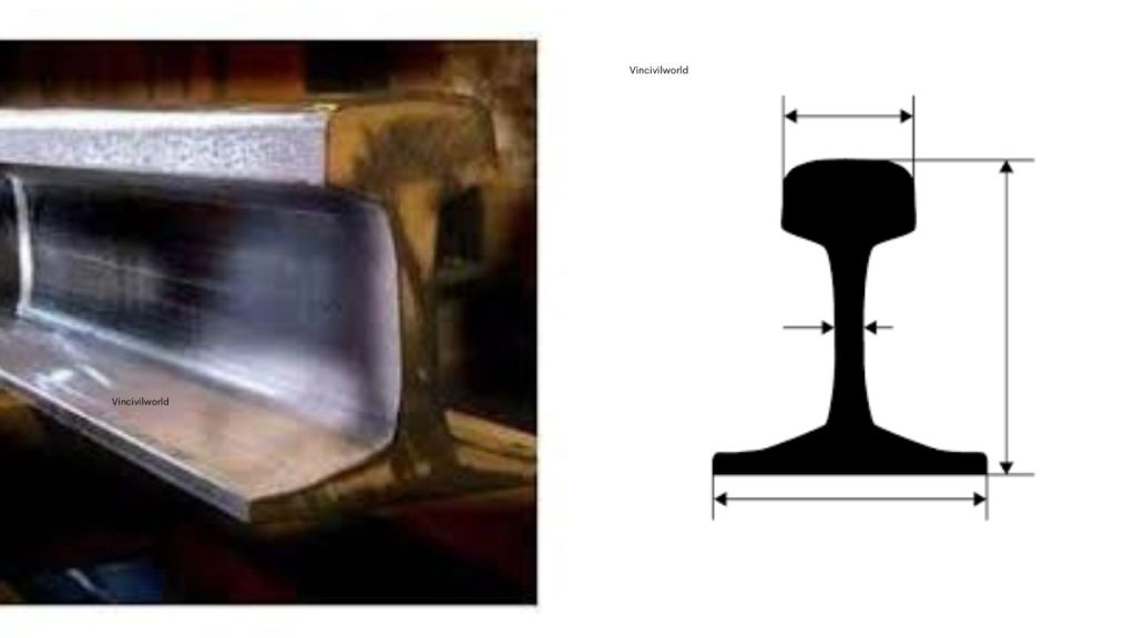
Double headed rails indicate the early stage of development. It essentially consists of three parts, such as upper table, web and lower table. Both the upper and lower tables were identical. They were introduced with the hope of doubling the life of rails.
When the upper table is worn out, the rails can be placed upside down. They can be reversed on the chair. This way, the lower table can be brought into use.
Illustration of double headed rails, showcasing the upper table, web, and lower table design, along with the rail’s mounting setup.
Double headed rails
But this idea soon turned out to be wrong. The continuous contact of the lower table with the chair made the surface of the lower table rough. Hence, the smooth running of the train was impossible.
Therefore, this type of rail is practically out of use. Nowadays, these rails vary in lengths from 20- 24.
The rail sections, whose foot and head are of same dimensions, are called double headed rails. In the beginning, these rails were widely used in the railway track.
The idea behind using these rails was that when the head had worn out due to rubbing action of wheels, the rails could be inverted. The rails could then be reused. But by experience, it was found that their foot could not be used as running surface because it also got corrugated under the impact of wheel loads.
Its time to meet the second type of rails which are bull headed rails.
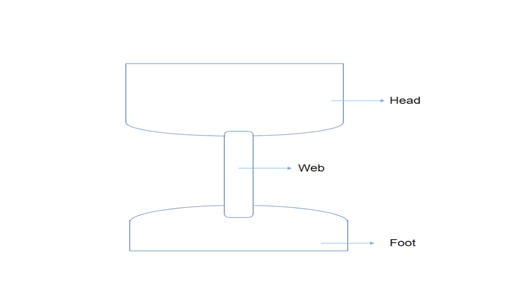
Bull headed rails
Diagram illustrating the structure of bull headed rails, showcasing individual components and their arrangement.
Bull headed rails
The rail section whose head dimensions are more than that of their foot are called bull headed rails. In this type of rail the head is made little thicker and stronger than the lower part by adding more metal to it. These rails also require chairs for holding them in position.
Bull headed rails are especially used for making points and crossings. This type of rail also consists of three parts, such as the head, the web and the foot. These rails were made of steel.
The head is of larger size than foot and the foot is designed only to hold up properly the wooden keys with which rails are secured. Thus, the foot is designed only to furnish necessary strength and stiffness to rails.
Two cast iron chairs are required per each sleeper when these rails are adopted. Their weight ranges from 85lb to 95lb and their length is up to 60ft.
That’s it about bull headed rails. Let’s move on to the third member in the list of types of rails, which are flat footed rails.
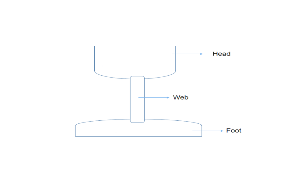
Flat footed rails
Detailed diagram of a flat footed rail, illustrating its unique design and dimensions.
Flat footed rails
The rail sections having their foot rolled to flat are called flat footed rails. This type of rail was invented by Charles Vignola in 1836.
It was initially thought that the flat footed rails could be fixed directly to wooden sleepers. This would eliminate chairs and keys required for the BH rails. But later on, it was observed that heavy train loads caused the foot of the rail to sink into the sleepers. The heavy train loads also made the spikes loose.
Flat footed rails consist of three parts, such as head web and foot. The foot is spread out to form a base. This form of rail has become so popular. About 90% of railway tracks in the world are laid with this form of rails.
Flat footed rails have the following advantages.
Advantages of flat footed rails
They do not need any chair and can be directly spiked or keyed to the sleepers. Thus they are economical.
They are much stiffer both vertically and laterally. The lateral stiffness is important for curves.
They are less liable to develop kinks and maintain a more regular top surface than bull headed rails.
They are cheaper than bull headed rails
The loads from wheels of trains are distributed over large number of sleepers and hence larger area which results in greater track stability, longer life of rails and sleepers, reduced maintenance, costs, rail failure and few interruptions to traffic
Industrial Railway Rails
Industrial railway rails are specially designed rails used in industrial environments such as factories, mines, and ports. These rails are heavier and more robust than conventional railway rails to withstand high axle loads, frequent stopping and starting, and harsh conditions. Typically, they conform to standards like the AREMA Class 1 and can weigh between 112 to 141 pounds per yard. Industrial rails provide durability, strength, and resistance to wear, ensuring reliability for transporting heavy goods and equipment within industrial premises.
A stack of various types of railway rails, showcasing their unique designs crucial for rail infrastructure.
Crane Rails
Crane rails are specialized rails designed to support the movement of overhead cranes and gantry cranes in industrial facilities. They have a wider head and base to provide stability and distribute heavy crane loads evenly. Crane rails are typically more rigid and wear-resistant than standard rails, often stocked in weights like 60 kg/m or higher. They ensure smooth crane operation, safety, and longevity under continuous heavy loading and lateral stresses encountered in crane tracks.
The Most Used Rail Profiles Worldwide Presently
In contemporary railway engineering, the flat footed rail profile is very prevalent. It is also known as the Vignole rail. It is the most widely used rail profile globally. This profile has a flat, wide foot. It can be spiked directly to sleepers. This design eliminates the need for additional support such as chairs. Flat footed rails are favored for their structural efficiency. They are known for durability and ease of installation. This makes them ideal for standard and heavy-duty railway tracks.
Common modern flat footed rail profiles include the internationally standardized UIC60 (60 kg/m), prevalent on mainline railways worldwide, and the 115RE profile (approximately 56.9 kg/m), widely used in North America. Regional variations such as DIN rails in Europe and other heavy or light profiles also follow the flat bottom design. These flat footed/Vignole rails offer superior load distribution, enhanced stability, and cost advantages over traditional bull headed rails, leading to their dominant use in global rail infrastructure.
Illustration of flat footed rail design, showcasing its profile and structure for railway applications.
Key Takeaways
Understanding the various types of rail is essential for optimizing railway infrastructure. Types of rail sections include double-headed rails, bull-headed rails, and flat-footed rails. Double-headed rails have symmetrical upper and lower tables. They aimed to extend rail life. However, they are now rarely used due to maintenance issues. Bull-headed rails feature a thicker head for strength and are commonly used in points and crossings. Flat-footed rails, introduced by Charles Vignole, are widely adopted in modern railways due to their ease of installation and cost-efficiency. Each of these types of rail sections serves specific needs, influencing track stability and performance.
Conclusion
In conclusion, the selection of rail types profoundly affects railway system efficiency. Types of rail sections, such as double-headed rails, bull-headed rails, and flat-footed rails, each have distinct characteristics and applications. Double-headed rails are largely obsolete, while bull-headed rails remain useful for specific rail components. Flat-footed rails, with their practical advantages, dominate modern rail systems. A comprehensive understanding of the types of rail and their properties is crucial. This is essential for effective rail system design and maintenance. It ensures optimal performance and longevity.
Was the article helpful? Let me know your thoughts in the comments.
Bitumen for roads is an important topic to understand when it comes to road construction. Bitumen is used in road construction because of the wide range of features and advantages it possesses over other pavement construction materials. The significance of bitumen in the construction of roads will be demonstrated in this article. In addition, we shall see bitumen road layers, various bituminous materials, cutback bitumen, bitumen grade, and bitumen properties.
Generally, tar is made by heating coal inside a chemical apparatus. Most tar is produced from coal as a byproduct of coke production, but it can also be produced from petroleum, peat or wood.
Bitumen for roads
The major steps in tar manufacturing are,
Coal undergoes carbonation and produces crude tar
Crude tar undergoes distillation/ refining and produces a residue
The residue blends with distilled oil fraction and produces tar
Desirable properties of bitumen- an important topic in bitumen for roads
The desirable properties of bitumen are,
Properties of Bitumen
Viscosity of bitumen during mixing and compaction is adequate
Bituminous material should not highly temperature and susceptible
In presence of water the bitumen should not strip off from aggregate
The adhesive property of bitumen binds together all the components without bringing about any positive or negative changes in their properties
Bitumen is insoluble in water and can serve as an effective sealant
Due to versatility property of Bitumen it is relatively easy to use it in many applications because of its thermoplastic property
Bitumen play a vital role in distributing the traffic loads on the pavement to the layers beneath
Bitumen for roads – Types of Bituminous materials
Okay. So, what are the types of bituminous materials that are used in flexible pavement construction? Below is the list for you.
Paving grade material
Modified bituminous binder
Cutback bitumen
Bitumen emulsion
Among the list, cutback bitumen is the major. Let me tell you more details about cutback bitumen.
Cutback bitumen
Cutback bitumen is the bitumen the viscosity of which is reduced by a volatile diluent. It is used in low-temperature mixing.
Three types of cutback bitumen are available
Rapid curing
Medium curing
Slow curing
The diluent while mixing varies with the type of cutback bitumen.
Type of cutback bitumen
Diluent
Rapid curing
Nafthal, gasoline
Medium curing
Carosine or diesel oil
Slow curing
High boiling point gas oil
Type of cutback bitumen and suitable diluent
Bituminous emulsion
A bitumen emulsion is a liquid product in which a substantial amount of bitumen suspended in a finely divided condition in an aqueous medium and stabilized by means of one or more suitable material
To determine the grade of bitumen, penetration test is conducted. The results are expressed in 1/10 mm. When penetration value is represented as 80/1000, it is called grading of bitumen.
The old method of grading is viscosity test. Two viscosities kinematic and absolute and penetration value by penetration test results are collected. Based on this, bitumen is graded. The tables shows the grade of bitumen and values of viscosity in accordance with penetration.
Grade of bitumen
Absolute viscosity
Kinematic viscosity
Penetration
VG 10
800
250
80- 100
VG 20
1000
300
60- 80
VG 30
2400
350
50- 70
VG 40
3200
400
40- 60
Grade of bitumen and viscosity
Let me tell you the application of each of the grade of bitumen now.
VG- 10- Used in spray application since viscosity is very less
VG- 20- Used in cold area
VG- 30- Commonly used in India
VG- 40- High grade bitumen used in high traffic areas
Okay. So, lets’ learn about the bituminous layers.
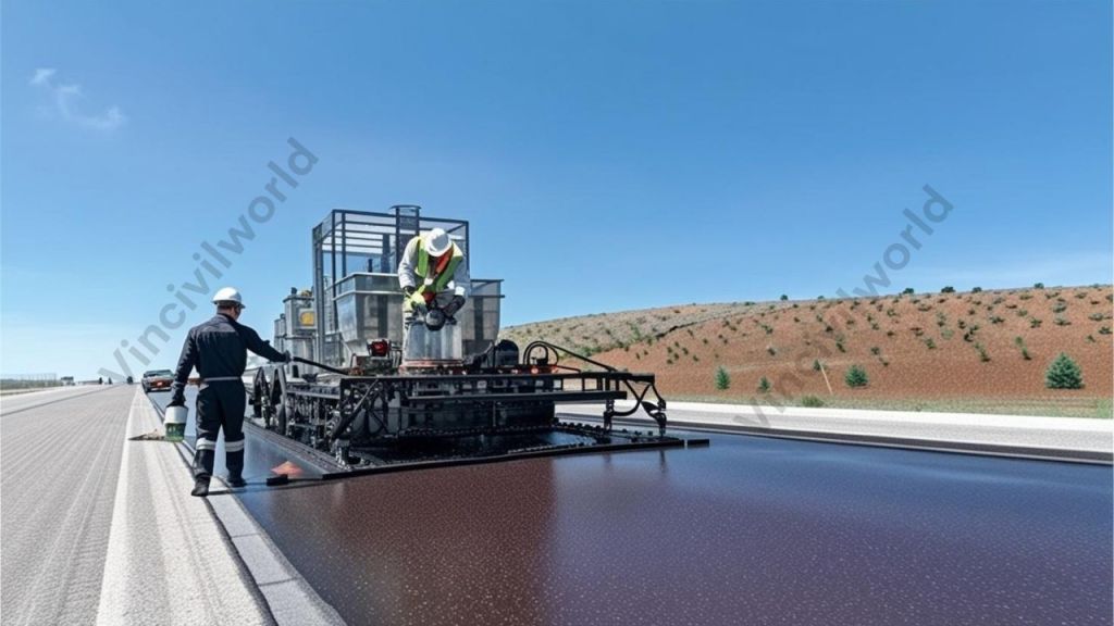
The bitumen road layers come in the surface layer shown in the figure above. The figure below shows that. Bituminous mix consists of aggregate and binder. Aggregate consists of coarse aggregate, fine aggregate and filler less than 0.075mm.
Bituminous concrete consists of aggregate and bitumen.
Thickness of base course depends on grading of aggregate
Dense graded aggregates are provided in base course. That is the permeability will be very less
Number of voids should be very less
Dense bituminous macadam should be given as a binder course
So, the trip is over. Hope the time you spend for reading about the bitumen for road was worth it.
Cutback bitumen (MC30, RC70) is used where quick curing is needed.
Bitumen ensures strong bonding between road layers and improves lifespan.
Engineers select bitumen grades based on climate and traffic needs.
Proper bitumen selection enhances pavement performance and sustainability.
Conclusion
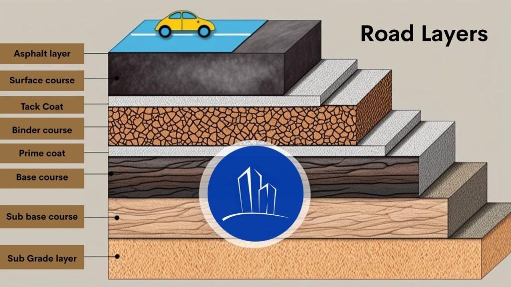
Bitumen for roads plays a critical role in the construction and performance of modern pavements. Its unique properties—such as waterproofing, adhesion, flexibility, and resistance to traffic loads—make it a preferred material for road engineers worldwide. Engineers employ various types and grades of bitumen for applications ranging from base layers to surface sealing, based on project requirements and environmental conditions. They use penetration and viscosity grades for high-traffic areas, while they choose emulsions and cutbacks for lower-volume roads and cooler climates. Each bitumen type serves a specific purpose in road layers like prime coats, binder courses, and tack coats. Ultimately, the correct selection and application of bitumen ensure a durable, cost-effective, and long-lasting road infrastructure.
Concrete road construction involves building durable pavements using cement concrete road techniques, which prioritize strength and longevity. This method uses layered systems called concrete road layers, including subgrade, sub-base, base, and surface layers, to ensure stability and load distribution. Unlike asphalt, road construction concrete offers higher resistance to weather, heavy traffic, and wear, reducing long-term maintenance costs. Concrete for road construction is preferred for its sustainability, as it reflects sunlight, lowering urban heat, and uses recyclable materials. A cement concrete road lasts 30–40 years, outperforming flexible pavements in lifespan and cost-effectiveness. Engineers choose concrete road construction for highways and urban roads due to its minimal upkeep and eco-friendly benefits. By optimizing concrete road layers and material quality, this method delivers safer, smoother, and more reliable infrastructure.
This article explores concrete road construction, highlighting its layered design, durability, and sustainability. It explains why cement concrete roads outperform asphalt, offering long-lasting, eco-friendly, and cost-effective solutions for modern infrastructure needs.
Structural components of Concrete Road Construction
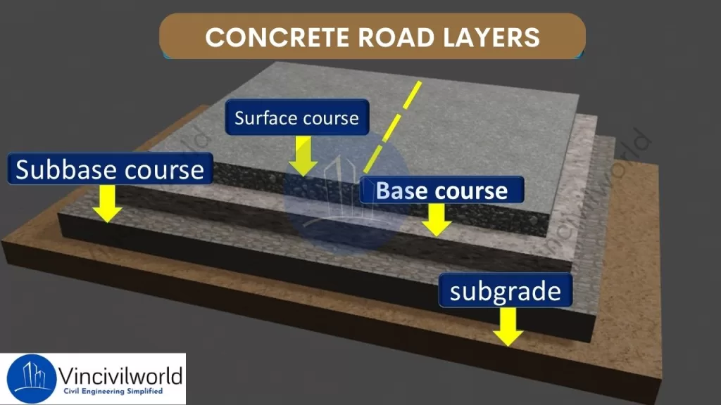
Concrete road construction relies on a well-structured system of layers to ensure durability and strength. These concrete road layers include the subgrade, sub-base, base course, and concrete slab. Each layer plays a critical role in distributing loads and preventing cracks. Proper road construction concrete techniques ensure the longevity of cement concrete roads, making them ideal for heavy traffic and harsh weather conditions. Let us explain each component in detail.
Concrete road construction – Layers
Subgrade
Engineers prepare the native soil to support the road structure, forming the subgrade. In concrete road construction, a stable subgrade is essential as it forms the foundation for all subsequent concrete road layers. Proper compaction of the subgrade prevents settlement and provides uniform support for the road construction concrete. A well-prepared subgrade enhances the durability of the cement concrete road by reducing the risk of cracks and deformations.
Sub-base
Positioned above the subgrade, the sub-base layer consists of granular materials like crushed stone or gravel. In concrete road construction, the sub-base serves to distribute loads and provides additional support to the upper concrete road layers. It also acts as a barrier against moisture, protecting the road construction concrete from potential damage. A properly installed sub-base enhances the overall performance of the cement concrete road.
Base Course
The base course lies directly beneath the concrete slab in concrete road construction. The base course consists of high-quality aggregates that create a stable platform for the pavement. It effectively transmits the loads from traffic to the underlying concrete road. Additionally, the base course plays a crucial role in enhancing the durability and performance of the pavement structure layers. A well-constructed base course is vital for the structural integrity of the cement concrete road, ensuring longevity and durability.
Concrete Slab (Pavement)
The concrete slab, or pavement, is the topmost layer in concrete road construction. This surface layer is made of road construction concrete and is designed to withstand direct traffic loads. The quality of the concrete for road construction used in this layer determines the road’s durability and service life. Proper curing and jointing of the concrete slab are crucial. These practices prevent cracks. They ensure a smooth, long-lasting cement concrete road surface.
Each of these layers is crucial in concrete road construction. They collectively enhance the pavement’s strength. They also improve its durability and longevity. Moreover, proper design and construction of these concrete road layers are essential to ensuring a high-quality cement concrete road. As a result, the pavement can effectively withstand the demands of heavy traffic. It can also endure varying environmental conditions. This ultimately provides a long-lasting and reliable transportation solution.
Types of Concrete Road Pavements
In concrete road construction, selecting the appropriate pavement type is crucial for durability and performance. There are three main types of concrete roads. These are Jointed Plain Concrete Pavement (JPCP), Jointed Reinforced Concrete Pavement (JRCP), and Continuously Reinforced Concrete Pavement (CRCP). Each type utilizes different concrete road layers and reinforcement methods to meet specific engineering requirements.
Jointed Plain Concrete Pavement (JPCP)
JPCP is the most commonly used type in concrete road construction. It consists of slabs with transverse joints spaced typically between 15 to 20 feet apart. These joints control cracking without the need for steel reinforcement. Dowel bars are often used to transfer loads across joints, enhancing the performance of the cement concrete road. The simplicity of design and construction makes JPCP a cost-effective choice for many road construction concrete projects.
Jointed Plain Concrete Pavement (JPCP)
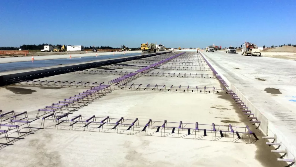
Jointed Reinforced Concrete Pavement (JRCP)
JRCP incorporates steel reinforcement within the concrete slabs and features longer joint spacing, typically ranging from 30 to 40 feet. As a result, the reinforcement effectively helps control cracking between the joints, thereby maintaining the structural integrity of the pavement. Additionally, dowel bars and tie bars are strategically placed at transverse and longitudinal joints, respectively, to ensure efficient load transfer and proper alignment.
Moreover, this design is particularly suitable for areas experiencing heavier traffic loads, as it provides enhanced durability and long-term performance. Consequently, JRCP serves as a reliable cement concrete road solution, offering both strength and stability. Ultimately, its combination of reinforcement and optimized joint spacing makes it an excellent choice for modern road infrastructure.
Jointed Reinforced Concrete Pavement (JRCP)
Contraction Joints
These are intentionally placed joints in the concrete pavement to control where cracks occur. In JRCP, the spacing of transverse joints typically ranges from 25 to 50 feet (7.6 to 15.2 meters). These joints allow the concrete to shrink as it cures, reducing the likelihood of random cracking.
Reinforcing Steel
JRCP incorporates reinforcing steel or steel mesh to hold cracks tightly together. While the longer slab lengths in JRCP make cracking inevitable due to concrete’s natural shrinkage and thermal contraction, the reinforcing steel ensures that cracks remain tight and do not widen significantly. This helps maintain the pavement’s structural integrity and load-bearing capacity.
Dowel Bars
Dowel bars are used at transverse joints to facilitate load transfer between adjacent slabs. These bars allow for vertical movement while ensuring that loads are effectively transferred across the joint, reducing stress concentrations and preventing faulting (unevenness at the joint).
Load Transfer Across Cracks
The reinforcing steel or wire mesh in JRCP not only holds cracks together but also assists in transferring loads across the cracks. This helps distribute traffic loads more evenly, reducing the risk of localized damage and extending the pavement’s service life.
Advantages of JRCP
Crack Control: The combination of joints and reinforcement ensures that cracks are controlled and do not compromise the pavement’s performance.
Durability: The use of reinforcing steel and dowel bars enhances the pavement’s ability to withstand heavy traffic and environmental stresses.
Load Distribution: Effective load transfer mechanisms reduce the risk of joint faulting and slab cracking.
Disadvantages of JRCP
Cost: The inclusion of reinforcing steel and dowel bars increases material costs. Construction costs also rise compared to simpler pavement types like Jointed Plain Concrete Pavement (JPCP).
Maintenance: JRCP is designed to control cracking. However, the presence of reinforcing steel can complicate repairs if the pavement eventually fails.
In summary, JRCP is a robust pavement design. It uses a combination of contraction joints, reinforcing steel, and dowel bars. These elements manage cracking and ensure effective load transfer. This makes it suitable for roads and highways subject to heavy traffic and environmental stresses.
Continuously Reinforced Concrete Pavement (CRCP)
CRCP is the most advanced type in concrete road construction, as it features continuous steel reinforcements throughout the slab. Consequently, this design eliminates transverse joints, making it particularly ideal for high-traffic areas such as highways and airports. Additionally, CRCP uses reinforcement to hold tightly spaced cracks together, thereby creating a smooth and highly durable surface.
Continuously Reinforced Concrete Pavement (CRCP)
Moreover, CRCP concrete road construction is especially suitable for high-traffic areas because it offers superior performance while requiring minimal maintenance. As a result, this construction method ensures long-lasting pavement that can withstand heavy loads and harsh environmental conditions. Ultimately, its combination of strength, durability, and reduced upkeep makes CRCP a preferred choice for modern infrastructure projects.
CRCP offers exceptional durability and requires minimal maintenance for cement concrete roads. The steel mesh prevents cracks and distributes traffic loads evenly across concrete road layers, ensuring a smooth and long-lasting surface. CRCP uses high-strength road construction concrete to withstand heavy loads and extreme weather conditions. Its seamless design reduces maintenance costs and enhances the performance of concrete road construction, making it a top choice for critical infrastructure projects.
Choosing the appropriate type of concrete pavement depends on factors such as traffic load, environmental conditions, and budget considerations. Each type offers distinct advantages in concrete road construction, contributing to the development of durable and efficient transportation infrastructure.
Advantages of Concrete Roads
Concrete roads offer several advantages over other paving materials:
Durability and Longevity: Concrete roads are known for their exceptional durability, as they can withstand heavy traffic loads and adverse weather conditions. As a result, they offer a longer service life compared to other road construction materials. Furthermore, this durability ensures lower maintenance costs over time, making concrete roads a cost-effective option for long-term use.
Low Maintenance Requirements: Once constructed, concrete roads demand relatively low maintenance. Their resistance to wear and tear reduces the frequency of repairs, making them a cost-effective choice in the long run.
Resistance to Weathering and Heavy Loads: Concrete’s high stiffness and negligible wear and tear make it resistant to environmental factors such as water, extreme temperatures, and UV radiation. This resistance helps maintain the structural integrity of the road over time.
Improved Fuel Efficiency for Vehicles: Concrete roads are more economical to drive on in terms of fuel consumption, as they reflect light better and provide a smoother surface, contributing to better fuel efficiency for vehicles.
Methods of construction of cement concrete roads
Cement concrete roads are constructed through three primary methods, each designed to meet specific project requirements and conditions.
Alternate Bay Method
In this approach, the contractor divides the road into alternate bays, typically ranging from 6 to 8 meters in length. They construct the road in these alternate sections, ensuring each bay cures properly before constructing the adjacent bays. This method allows for effective curing and prevents premature construction, ultimately enhancing the quality of the road. This method helps in managing shrinkage and thermal stresses effectively, reducing the likelihood of cracks. However, it requires more time to complete since only alternate sections are worked on at a time. Additionally, during adverse weather conditions, water may collect in the unconstructed bays, potentially causing delays.
Continuous Bay Method
Also known as the strip method, this technique involves constructing the entire width of the road continuously without any breaks from one end to the other. Transverse joints, known as dummy joints, are provided at regular intervals (typically around 5 meters) to control cracking by creating planes of weakness. This method ensures a uniform surface and is suitable for projects requiring rapid completion. However, it necessitates careful planning to manage the setting time of concrete and to ensure proper curing across the entire stretch.
Expansion Joint and Strip Method
In this method, the engineers incorporate expansion joints at regular intervals to accommodate temperature-induced expansions and contractions. This prevents uncontrolled cracking and ensures the road remains structurally stable over time. By strategically placing these joints, they allow for controlled movement while maintaining the integrity of the pavement.These joints allow the concrete slabs to expand and contract with temperature variations without causing damage to the pavement. This technique is essential for long stretches of pavement, especially in regions experiencing significant temperature fluctuations. Proper placement and construction of these joints are crucial to maintain the structural integrity and longevity of the road.
Each method offers distinct advantages, and the choice depends on factors such as project scale, environmental conditions, and desired durability.
Steps involved in road construction
Constructing a cement concrete road involves several critical steps to ensure durability and longevity. Each phase plays a vital role in achieving a high-quality pavement.
Preparation of Subgrade
The subgrade is the native soil layer that serves as the foundation for the road. Preparation involves clearing the site of vegetation, debris, and any unsuitable materials. The soil is then leveled and compacted to achieve the desired density and strength. Proper subgrade preparation ensures uniform support for the pavement, preventing future settlement and distress. In cases where the subgrade soil is weak, stabilization techniques or additional layers may be applied to enhance its load-bearing capacity.
Placement of Formwork
Formwork refers to temporary molds used to shape and support the concrete until it hardens. In road construction, workers set sturdy forms along the edges of the proposed pavement to define its boundaries and maintain the desired thickness. They must accurately align and securely anchor these forms to withstand the pressure of the poured concrete. Consequently, proper formwork ensures consistent pavement dimensions and well-formed edges, contributing to the overall structural integrity.
Mixing and Pouring of Concrete
Workers prepare concrete by mixing cement, aggregates (such as sand and gravel), water, and any necessary admixtures in specified proportions. They perform this mixing either on-site or at a batching plant. Afterward, they transport the mixed concrete to the site and pour it into the prepared formwork. It’s essential to pour the concrete promptly to prevent premature setting. Consistent mixing and timely pouring ensure a uniform composition, which is crucial for the pavement’s strength and durability
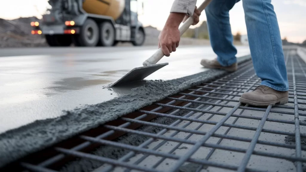
Compaction and Finishing
After pouring the concrete, workers must compact it to eliminate air voids and achieve the desired density. They typically use vibrators to ensure the concrete settles properly around any reinforcement and into all corners of the formwork. Following compaction, they level and smooth the surface using tools like screeds and trowels. Proper compaction is crucial, as it enhances the strength and durability of the concrete by removing entrapped air and consolidating the mixture. Finishing may also involve creating surface textures to enhance skid resistance. Proper compaction and finishing are vital for the pavement’s structural performance and surface quality.
Curing Process
Curing involves maintaining adequate moisture and temperature conditions to allow the concrete to achieve its intended strength. This process typically lasts for several days and can be accomplished by methods such as covering the surface with wet burlap, applying curing compounds, or using plastic sheeting. Proper curing prevents the concrete from drying too quickly, which can lead to surface cracking and reduced durability. It’s a critical step to ensure the longevity of the pavement.
Joint Cutting and Sealing
Once the concrete has gained sufficient strength, joints are cut into the pavement to control cracking caused by temperature changes and shrinkage. These joints are typically spaced at regular intervals and can be of various types, including contraction, expansion, and construction joints. After cutting, workers thoroughly clean the joints and carefully apply appropriate sealants. This process effectively prevents the infiltration of water and debris, which could otherwise compromise the pavement’s integrity. Moreover, proper joint cutting and sealing play a crucial role in maintaining the road’s overall performance while significantly extending its service life.
Furthermore, each of these steps is essential for constructing a durable and long-lasting cement concrete road. By paying close attention to every phase, from preparation to finishing, workers ensure that the pavement can withstand heavy traffic loads and varying environmental conditions throughout its intended lifespan. Consequently, a well-executed construction process leads to stronger, more resilient roads that require minimal maintenance over time.
Disadvantages of concrete road construction
Concrete road construction offers durability and strength, but it also presents several challenges:
High Initial Construction Cost: Building concrete roads requires a significant upfront investment. This is due to the cost of materials and skilled labor.
Extended Construction Time: The curing process of concrete is time-consuming, leading to longer project durations compared to asphalt roads.
Difficulty in Maintenance: Repairing damaged concrete roads can be challenging. Often, it requires replacing entire slabs rather than simple patching.
Lower Comfort and Noise Issues: Concrete’s rigidity can result in a noisier and less comfortable driving experience due to its poor shock absorption and higher noise levels.
Susceptibility to Cracking: Concrete roads are prone to cracking under heavy loads and temperature variations, which can compromise their structural integrity over time.
These factors should be carefully considered when planning and implementing concrete road projects.
Maintenance Practices for Concrete Roads
Concrete road resurfacing and rehabilitation involve various methods to restore pavement functionality and extend service life:
Joint and Crack Sealing: Involves cleaning and filling existing joints and cracks with sealant to prevent water infiltration and debris accumulation, thereby reducing further deterioration.
Slab Stabilization: Addresses voids beneath concrete slabs by injecting grout to restore support and prevent faulting or cracking.
Diamond Grinding: Removes surface irregularities and restores smoothness by grinding the concrete surface, improving ride quality and skid resistance.
Partial-Depth Repair: Targets surface-level distress by removing and replacing the top portion of the slab, addressing issues like spalling.
Full-Depth Repair: Involves removing and replacing entire concrete slabs or sections to address severe damage extending through the slab.
Load Transfer Restoration: Enhances load distribution across joints by installing dowel bars, improving structural capacity and extending pavement life.
Concrete Overlays: Applies a new concrete layer over existing pavement to increase structural capacity and address surface deficiencies.
Selecting the appropriate method depends on the pavement’s condition, distress types, and project objectives.
Innovations and Future Trends in Concrete Road Construction
Smart concrete and self-healing materials represent significant advancements in construction technology. Key points include:
Self-Sensing Capabilities: Smart concrete can monitor its own structural health. It does so by embedding sensors or conductive materials. This allows it to detect stress or damage in real-time.
Self-Healing Mechanisms: Incorporating materials like superabsorbent polymers or specific bacteria enables the concrete to autonomously repair cracks, enhancing durability and reducing maintenance needs.
Environmental Benefits: Extending the lifespan of structures and reducing the need for repairs contribute to sustainability in construction.
Enhanced Durability: Self-healing properties allow the concrete to recover from internal damage without external intervention, limiting reinforcement corrosion and concrete deterioration.
Innovative Additives: The use of carbon nanotubes, mineral admixtures, and shape memory alloys improves the unique properties of smart concrete.
These innovations aim to create more resilient, sustainable, and low-maintenance infrastructure.
Key Takeaways
Concrete road construction offers unparalleled durability and longevity, often lasting 20-40 years, which is two to four times longer than asphalt roads.
This longevity translates to lower maintenance costs over time, making it a cost-effective choice for modern infrastructure. The typical layered design—comprising subgrade, sub-base, base, and concrete slab—ensures exceptional strength and stability. Although the initial investment is higher compared to asphalt, the long-term savings and environmental benefits make concrete road construction a wise investment. Innovations such as self-healing concrete, which can repair its own cracks, further enhance performance and extend service life.
Proper curing, jointing, and high-quality materials are critical to success. Despite challenges like cracking and temperature sensitivity, concrete road construction remains a reliable solution for highways, urban roads, and industrial zones, ensuring safe and sustainable travel for decades.
Conclusion
Concrete road construction is a cornerstone of durable and sustainable infrastructure. Its ability to withstand heavy traffic, harsh weather, and long-term wear makes it ideal for modern roadways. By optimizing concrete road layers and using high-quality materials, engineers can create pavements that last 30–40 years with minimal maintenance. While challenges like cost and cracking exist, advancements in technology and construction techniques continue to improve its efficiency and performance. Embracing concrete road construction ensures safer, smoother, and more eco-friendly roads, paving the way for resilient and future-ready transportation networks.
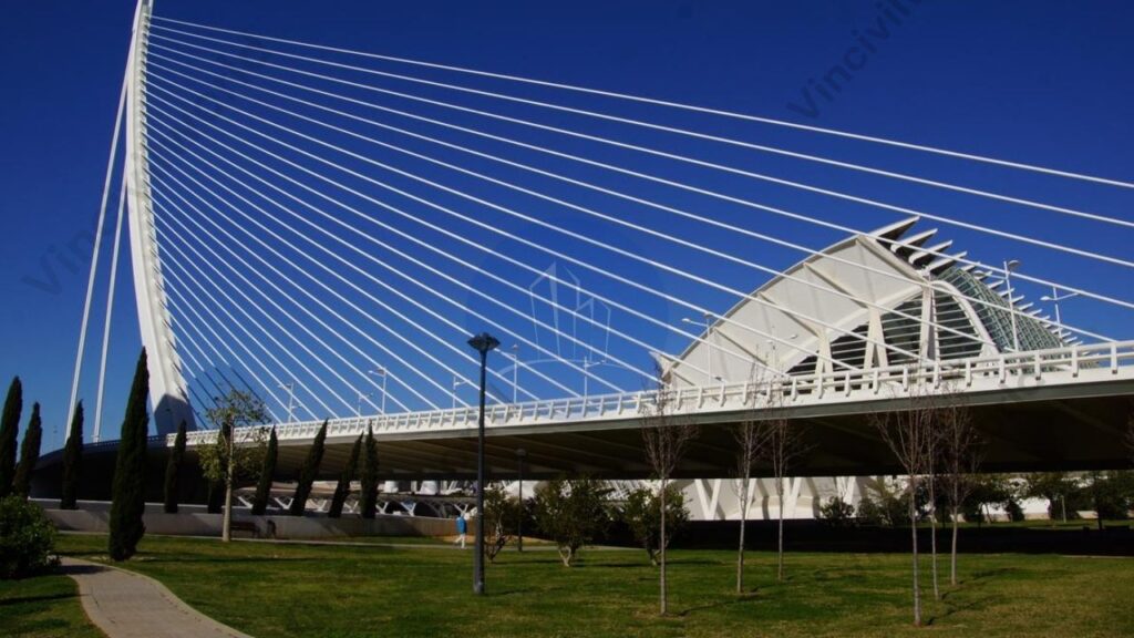
A cable stayed bridge is a modern engineering marvel known for its strength, efficiency, and aesthetic appeal. It uses one or more towers to support the bridge deck through a series of cables, which transfer the load directly to the foundation. Unlike suspension bridges, the cables in a cable stayed bridge connect directly from the deck to the towers in a straight line. This design provides greater rigidity, making it ideal for long spans and challenging terrain.
Cable stayed bridges are widely used for highway crossings, urban connections, and river spans due to their cost-effectiveness and adaptability. The distinctive arrangement of cable-stayed bridge cables creates visually striking structures that enhance the skyline. Some famous cable-stayed bridge examples include the Millau Viaduct in France and the Russky Bridge in Russia. With their efficient load distribution and elegant design, cable-stayed bridges continue to shape modern infrastructure globally.
In this article, we will explore the key components, types, and advantages of a cable-stayed bridge. We’ll also explain how cable stayed bridge cables function, discuss various construction techniques, and highlight notable cable-stayed bridge examples. By the end, you’ll understand why this design is widely used in modern infrastructure projects.
A cable-stayed bridge is a type of bridgewhere the deck is directly supported by cables connected to one or more towers/ pylons . The towers bear the load, and the cables transfer the weight to the foundation, creating a balanced and efficient structure. Unlike suspension bridges, where cables run horizontally between towers, cable-stayed bridge cables are attached directly from the deck to the tower in a straight or fan-like arrangement. This design provides superior stiffness and requires less material, making it cost-effective and suitable for long spans.
Cable-stayed bridges are common in modern infrastructure due to their strength and aesthetic appeal. In India, the Bandra-Worli Sea Link serves as a well-known example of this type of bridge. It showcases the country’s advancements in bridge engineering. Other famous cable-stayed bridge examples include the Sutong Bridge in China and the Øresund Bridge connecting Denmark and Sweden. These bridges exemplify their efficiency in various applications.
How Does a Cable-Stayed Bridge Work?
A cable-stayed bridge works by using a combination of towers (pylons) and stay cables to support the bridge deck. The towers, which are vertical structures, act as the primary load-bearing elements. Stay cables run directly from the towers to the deck in either fan, harp, or radial patterns. These patterns distribute the weight of the bridge and its traffic evenly.
The cables are tensioned to hold up the deck. They transfer the weight from the deck to the towers. The towers then channel the load down to the foundation. This design allows the bridge to span long distances without the need for additional piers. This makes it efficient and cost-effective for crossing large bodies of water or valleys. The tension in the cables and the compression in the towers create a balanced system. It allows the cable-stayed bridge to remain stable under heavy loads. This includes traffic, wind, and environmental stresses.
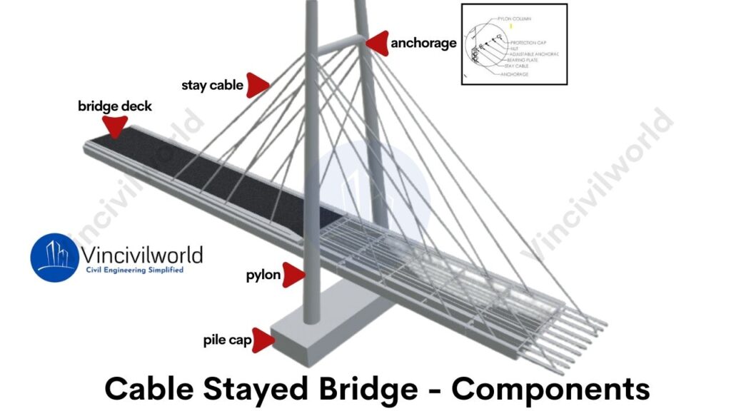
Key Components of a Cable-Stayed Bridge
A cable-stayed bridge consists of several essential components that work together to create a stable and efficient structure. Each part plays a crucial role in supporting the deck and transferring the load through the cable-stayed bridge cables. Below are the key components:
Towers/Pylons
Stay Cables
Deck Structure
Anchorages
Towers/Pylons
Towers, also known as pylons, are the vertical structures that support the cable-stayed bridge cables. They carry the majority of the load by transferring it to the foundations. Towers are usually made of concrete or steel, depending on the bridge design. A well-known example is the Bandra-Worli Sea Link in India, where towering pylons define its unique structure.
Types of Towers (Pylons)
Cable-stayed bridge towers come in various shapes based on design needs and aesthetics. Common types include A-shaped, H-shaped, and single-column towers. A-shaped towers, like those seen in the Bandra-Worli Sea Link in India, provide stability for long spans. H-shaped towers offer simplicity and strength, while single-column towers are ideal for minimalist designs. These towers bear the load of the thereby ensuring the structure’s integrity.
Stay Cables
Stay cables are the cables that directly connect the deck to the towers. These cables carry the weight of the bridge deck and the traffic. In cable-stayed bridges, the cables are arranged in different patterns, like fan or harp styles. These cables allow for flexibility and strength, ensuring the stability of the bridge.
These cables are typically made of high-strength steel strands or parallel wire strands for durability. Stay cables are encased in plastic sheaths to protect against corrosion. They are then grouted with special materials. This process further increases their lifespan and resistance to environmental damage.
Types of Stay Cables
Stay cables are arranged in different patterns, depending on the bridge design. The main types include fan-shaped, harp-shaped, and radial. In fan-shaped designs, the cables spread out from a single point at the top of the tower. In harp-shaped designs, the cables run parallel, creating a clean, sleek appearance. Radial patterns are used for smaller spans, with cable-stayed bridge cables directly supporting the deck.
Deck Structure
The deck structure forms the road or walkway of the cable-stayed bridge. It is supported by the stay cables and often consists of steel or reinforced concrete. The deck must distribute the load evenly across the bridge. In many cable-stayed bridges in India, the deck is designed to handle heavy vehicular traffic. It can also withstand environmental conditions.
Types of Deck Structures
Decks in cable-stayed bridges can be constructed using steel, concrete, or composite materials. Concrete decks are heavy but offer high durability, while steel decks are lighter, making them suitable for longer spans. Composite decks, combining steel and concrete, offer the best of both worlds, balancing weight and strength. The deck structure must efficiently transfer loads to the stay cables and towers.
Decks in cable-stayed bridges can be constructed using steel, concrete, or composite materials. Concrete decks are heavy but offer high durability, while steel decks are lighter, making them suitable for longer spans. Composite decks, combining steel and concrete, offer the best of both worlds, balancing weight and strength. The deck structure must efficiently transfer loads to the stay cables and towers.
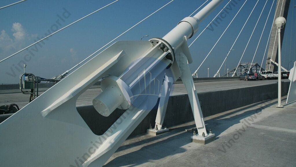
Anchorages
Anchorages are crucial in securing the stay cables to the deck and the towers. They ensure that the load is evenly transferred and that the cables remain in tension. Proper anchorage design is vital to prevent movement in the cables, ensuring the bridge’s durability and long-term stability.
Types of Anchorages
Anchorages are essential for securing the stay cables to the deck and towers. The two main types are external and internal anchorages. Inspecting and maintaining external anchorages is simpler due to their visibility, while embedding internal anchorages within the deck or tower offers added protection. Both types ensure the cable-stayed bridge maintains its tension and stability under varying loads.
Types of Cable-Stayed Bridges
Cable stayed bridges are classified based on the following basis
Based on the Arrangement of Pylons
Based on the shape of Pylons
Based on Cable Arrangements
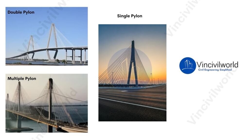
Based on the Arrangement of Pylons
Cable-stayed bridges can be classified by the arrangement of pylons (towers) used to support the deck. The most common types include single-pylon bridges. They have a central tower supporting cables that radiate outward. There are also double pylon bridges and multiple-pylon bridges, which feature two or more pylons placed along the bridge deck. Another variation is asymmetric pylon bridges. The pylons are of different heights or placed off-center. This accommodates specific design needs or terrain constraints.
Multiple-Tower
Multiple-tower cable-stayed bridges use two or more pylons to support longer spans. Engineers often use this type of bridge for large river crossings. These areas require extensive span coverage. Multiple towers distribute the load across a larger area.
Single-Tower
Single-tower cable-stayed bridges feature a single pylon or tower that supports the entire bridge structure. Consequently, narrow waterways or urban environments with limited space are ideal for these bridges. In addition, they provide a sleek and minimalist design.
Double Pylons
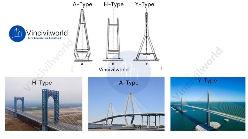
Based on the shape of Pylons
H-Shaped Pylons: These pylons feature two vertical legs. A horizontal beam connects them at the top. This design offers high stability and evenly distributes forces.
A-Shaped Pylons: The pylons are tapered at the top. They resemble the letter “A,” which gives a more streamlined appearance. This design efficiently channels forces down the legs.
Diamond-Shaped Pylons: These pylons are wider at the base and converge near the top, forming a diamond shape. They offer a unique aesthetic and strong structural support.
Y-Shaped Pylons: These pylons resemble the letter “Y.” They have a single leg splitting into two arms at the top. This design offers both flexibility and strength.
Each shape provides distinct structural advantages. The choice depends on the specific needs of the bridge design, aesthetics, and load distribution requirements.
Based on Cable Arrangements
Cable arrangements in cable-stayed bridges generally follow three main patterns:
Radial (fan): Cables radiate from the top of the pylon to various points along the deck, creating a fan-like pattern.
Parallel (harp): Cables are attached at regular intervals along the pylon and deck, forming a parallel arrangement.
Semi-fan: A hybrid design where cables partially fan out but with more uniform spacing, balancing aesthetics and structural efficiency.
Radial Pattern
The cables radiate outward from the pylon to the deck, forming a fan-like shape. This arrangement offers efficient load distribution.
Harp/parallel Pattern
The cables are arranged in a parallel pattern, resembling the strings of a harp. This configuration is commonly used for bridges with a central pylon
Fan Pattern
In a fan pattern, stay cables converge at the top of the tower, spreading out to the deck in a fan-like arrangement. Engineers commonly use this design for cable-stayed bridges with shorter spans, offering both strength and visual distinction.
Advantages of Cable-Stayed Bridges
Cable-stayed bridges offer numerous benefits due to their efficient design and versatility. Moreover, they are ideal for long spans and challenging terrains, as they provide both structural stability and aesthetic appeal. Below are the key advantages:
Fast Construction
The modular construction process of cable-stayed bridges allows for quicker building, reducing disruptions to surrounding areas and environments.
Cost-Effective Construction
Cable-stayed bridges use fewer materials. They require less maintenance compared to suspension bridges. This results in lower construction costs and long-term maintenance costs.
Efficient Load Distribution
Stay cables directly transfer the deck’s load to the towers. This reduces the need for multiple support piers. It simplifies construction and allows for longer spans.
Versatile Design
Cable-stayed bridges offer flexibility in design. They adapt to different structural and architectural needs through various cable arrangements. These arrangements include fan, harp, or radial patterns.
Aesthetic Appeal
The visible arrangement of cable-stayed bridge cables creates a striking, modern look. It enhances the visual landscape of urban or natural settings.
Challenges and Limitations of Cable-Stayed Bridges
While cable-stayed bridges offer many advantages, they also come with certain challenges that impact their design, construction, and long-term performance.
Complex Construction Techniques
Building cable-stayed bridges requires specialized engineering knowledge and equipment. The tensioning of cables, alignment of towers, and precision needed for the cable-stayed bridge cables require high-level expertise. This expertise can increase the complexity and cost of construction.
Maintenance Requirements
Although durable, cable-stayed bridges require regular inspections and maintenance, particularly for the stay cables. Environmental factors like corrosion and wind-induced vibrations can affect cable performance. These issues lead to increased maintenance efforts. This ensures the long-term stability of the structure.
Wind and Seismic Vulnerability
They are sensitive to strong winds and seismic activity. The flexibility of the cables can lead to vibrations or oscillations. If not managed through proper dampening systems, these vibrations may compromise the structure’s stability during severe weather or earthquakes.
Accumulation of snow
The cable-stayed bridges will accumulate ice due to environmental conditions. This ice will cause great harm to the traffic safety below the bridges.
High Initial Costs
These structures are generally cost-effective in the long run. However, they can incur high initial construction costs. This is due to the specialized materials and engineering that they require. The use of advanced materials for stay cables and pylons adds to the upfront expense of the project.
Construction Techniques for Cable-Stayed Bridges
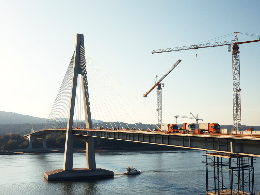
Cable-stayed bridges require precise construction techniques to ensure structural integrity and stability. The process begins with the construction of the towers, which are the main vertical supports. These towers must be strong enough to handle the immense forces transmitted by the cables. Once the towers are in place, deck sections are incrementally installed, typically using a cantilever method. This involves placing deck segments starting from the towers and progressing outward in both directions to maintain balance.
The construction team anchors the cables to the deck and tower, supporting the deck as the build progresses. They continuously adjust the cable tension to ensure the deck stays level. High-strength steel cables are essential. They transfer the load from the deck to the towers. This reduces bending moments in the deck structure.
Cable stayed bridge under construction
The construction process also requires careful consideration of material properties and cable tension forces, with adjustments often calculated using advanced methods like finite element analysis. Designers must give the bridge deck high torsional rigidity to resist twisting forces caused by uneven loads, ensuring long-term durability. Regular monitoring and adjustments during the construction phases are critical to maintaining the bridge’s alignment and stability
Comparison Between Cable-Stayed and Suspension Bridges
Feature
Cable-Stayed Bridges
Suspension Bridges
Structural Design
Cables directly connect the deck to the towers.
Cables run from towers to anchorages, supporting the deck via smaller vertical cables.
Main Cables
Fewer, shorter cables, anchored directly to the towers.
Long, continuous cables running over towers, anchored at both ends.
Cable Arrangement
Radial or fan-shaped pattern from towers to deck.
Vertical hangers suspend the deck from main cables.
Tower Height
Towers are shorter compared to suspension bridges.
Taller towers are required to support the long, continuous main cables.
Span Length
Best suited for medium spans (typically 200 to 1,000 meters).
Suitable for long spans (over 1,000 meters).
Construction Method
Faster to build as deck sections and cables are installed incrementally.
Requires extensive anchoring and time-consuming construction, especially for long spans.
Deck Support
Cables directly support the deck, providing greater stiffness.
The deck is supported by vertical hangers, allowing for more flexibility.
Torsional Stiffness
Higher torsional stiffness, making it less prone to twisting under loads.
Lower torsional stiffness, making it more flexible and vulnerable to twisting.
Cost
Generally more economical for medium spans.
Higher construction costs, particularly for long spans.
Maintenance
Lower maintenance costs due to fewer cables and less complex structure.
Higher maintenance costs due to more extensive cable systems and anchorages.
Aesthetics
Modern, sleek appearance with visible cables fanning from the towers.
Iconic and graceful with sweeping main cables and vertical hangers.
Examples
Millau Viaduct (France), Vasco da Gama Bridge (Portugal)
Golden Gate Bridge (USA), Akashi Kaikyō Bridge (Japan)
This comparison highlights the key differences in design, function, and applications between cable-stayed and suspension bridges
Famous Examples of Cable-Stayed Bridges Around the World
Here’s a list of famous cable stayed bridges around the world:
Millau Viaduct (France) – One of the tallest bridges globally, known for its elegance and engineering.
Vasco da Gama Bridge (Portugal) – The longest bridge in Europe, spanning 12.3 km over the Tagus River.
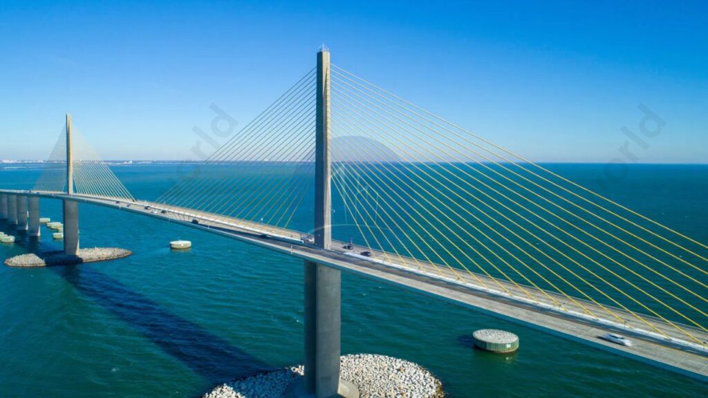
Sunshine Skyway Bridge (USA) – An iconic cable-stayed bridge in Florida, noted for its striking design.
Sutong Bridge (China) – Famous for its long span, once the longest cable-stayed span in the world.
Russky Bridge (Russia) – Holds the record for the longest cable-stayed span, connecting Russky Island to mainland Russia.
These bridges exemplify cutting-edge engineering and aesthetic appeal.
Applications of Cable-Stayed Bridges in Modern Infrastructure
Here’s a list of applications in modern infrastructure:
Highway Crossings: They efficiently connect major roadways, facilitating smoother traffic flow.
Railway Bridges: Ideal for spanning railway lines, minimizing disruptions to train services.
Urban Infrastructure: Often used in city planning to enhance connectivity between districts.
Waterway Crossings: They provide essential links over rivers and lakes, supporting commercial and recreational navigation.
Pedestrian and Bicycle Paths: Some designs incorporate dedicated lanes for non-motorized traffic, promoting eco-friendly transport.
Iconic Landmarks: Their aesthetic appeal makes them popular for constructing visually striking landmarks.
These applications demonstrate the versatility and effectiveness in various infrastructure projects
The Future of Cable-Stayed Bridges
The future of cable-stayed bridges is promising, driven by advancements in materials and engineering techniques. Innovations such as high-strength steel and fiber-reinforced polymers will enhance durability and reduce maintenance costs. Additionally, the integration of smart technologies, like sensors for real-time monitoring, will improve safety and efficiency. As cities continue to expand, cable-stayed bridges will meet infrastructure demands and maintain aesthetic appeal. This makes them increasingly relevant in modern urban planning.
Key takeaways
Here are the key takeaways
Efficient Load Distribution: They distribute loads effectively through towers and stay cables.
Aesthetic Appeal: Their unique design contributes to the visual beauty of infrastructure.
Long Spans: Capable of spanning long distances without multiple piers.
Cost-Effective Construction: Typically cheaper and quicker to construct compared to other bridge types.
Key Components:
Towers: Support the bridge deck.
Stay Cables: Connect the towers to the deck.
Deck Structures: The surface of the bridge.
Anchorages: Secure the cables.
Configuration Variations: Includes fan, harp, and radial patterns to meet different design requirements.
Advantages: Faster construction and lower maintenance costs.
Challenges: Sensitivity to wind and seismic activity.
Notable Examples: Includes the Millau Viaduct and the Bandra-Worli Sea Link, illustrating their significance in modern infrastructure.
Conclusion
Cable-stayed bridges are remarkable engineering achievements characterized by their efficient load distribution and aesthetic appeal. They use towers to support the bridge deck. A system of stay cables allows for long spans without multiple piers. This design not only enhances structural rigidity but also offers cost-effective construction. Key components include towers, stay cables, deck structures, and anchorages. They come in various configurations such as fan, harp, and radial patterns to suit different needs. Cable-stayed bridges offer advantages like faster construction and lower maintenance costs. However, they also face challenges related to sensitivity to wind and seismic activity. Notable examples include the Millau Viaduct and the Bandra-Worli Sea Link, showcasing their significance in modern infrastructure.