Gypsum plastering offers a modern, efficient solution for wall finishing with a smooth, durable surface. Unlike traditional plastering methods, plastering with gypsum is faster and requires less curing time, making it an excellent choice for construction and remodeling projects. Gypsum for plastering is also highly effective for indoor spaces due to its thermal insulation and fire-resistant properties. This blog will cover the advantages and disadvantages of gypsum plaster, along with essential tips for achieving quality results on a gypsum plaster wall.
Plastering is one of the most important activities involved in the construction of a building. The aesthetic looks of a structure depend totally on its finishing quality and workmanship. Beautiful and elegant interiors require a perfect plaster finish. The plaster finish has to be smooth, durable, and long-lasting and can retain the costly surface finishes and maintains the charm and sheen for years.
- Gypsum plastering– A plastering alternative
- What is gypsum plaster?
- Advantages of Gypsum Plaster over conventional plaster?
- Setting time & construction speed – Gypsum plaster
- Gypsum plaster- Shrinkage cracks eliminated
- Application and workability
- High Productivity
- Curing and water wastage
- Wastage and house keeping
- Strength and durability
- Quality of finish
- Environmental friendly and Green Building material.
- Acoustic properties
- Fire resistant
- Thermal conductivity
- Economical product
- Rust inhibitor & anti fungal
- Disadvantages of Gypsum plaster
- Conclusion
Gypsum plastering– A plastering alternative
Cement plaster is the most common plastering method adopted almost everywhere due to its excellent durability standards. The major ingredient of conventional cement plaster is river sand. Because of environmental issues and government-imposed bans, there was a huge scarcity of sand which in turn lead to a drastic price increase. No availability of quality workmanship and aggressive construction schedules compelled to adopt an alternative solution to conventional cement plaster.
Gypsum plaster is the best alternative for cement plaster. Gypsum plaster is an environmental friendly, economic, durable, and time-saving plaster material.
Why gypsum plaster is a perfect alternative?
This article takes you to the factors that make gypsum plaster a superior alternative when compared to conventional cement sand plaster.
What is gypsum plaster?
Gypsum plaster is made from mineral gypsum or gypsum rock by complete or partial dehydration of water. Gypsum heated at a temperature of 150-180 degrees centigrade dehydrates and remove 2/3 rd water. The material obtained after the water dehydration is a hemihydrate (CaSO4. 1⁄2H2O) known as Gypsum Hemihydrate or Plaster of Paris.

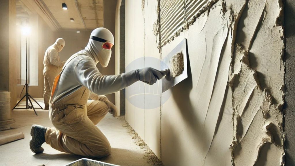
Gypsum plaster is produced by mixing the dry POP powder with clean water. It is mixed in recommended proportions to make a consistent slurry. This gypsum plaster slurry is applied at the desired thickness on walls and ceiling by skilled applicators. This process is called gypsum plastering.
Gypsum is a natural mineral and POP is manufactured from Gypsum. POP mixed with water and used for plastering walls is called gypsum plaster.
Advantages of Gypsum Plaster over conventional plaster?
Gypsum plaster had been used for centuries in the construction space and is a time tested process for plastering interior walls. Gypsum plaster provides excellent thermal and acoustic properties while providing a superior and smooth finish.
Gypsum plaster got a lot of superior qualities when compared to conventional plaster.
Setting time & construction speed – Gypsum plaster
| Gypsum plaster | Conventional plaster |
| No pre-curing and post-curing is required. Paint and other finishes can be applied after 3 days of application. | Requires 21-28 days pre-curing and post-curing period. Finishes can only be applied after 21-28 days. |
Removing the pre-curing and post-curing period in gypsum plaster can substantially squeeze the construction schedule. It can also speed up the project delivery.
Gypsum plaster- Shrinkage cracks eliminated
| Gypsum plaster | Conventional Plaster |
| No heat is generated during the hardening process thereby eliminating shrinkage cracks in gypsum plaster. | In the hardening process, heat is generated. Additionally, the mortar dries suddenly. As a result, cement plaster tends to develop fine shrinkage cracks. Drying shrinkage is around 0.07%. |
| Got high tensile and flexural strength that resists fine cracks | Cement plaster has low tensile and flexural strength and hence develops cracks. |


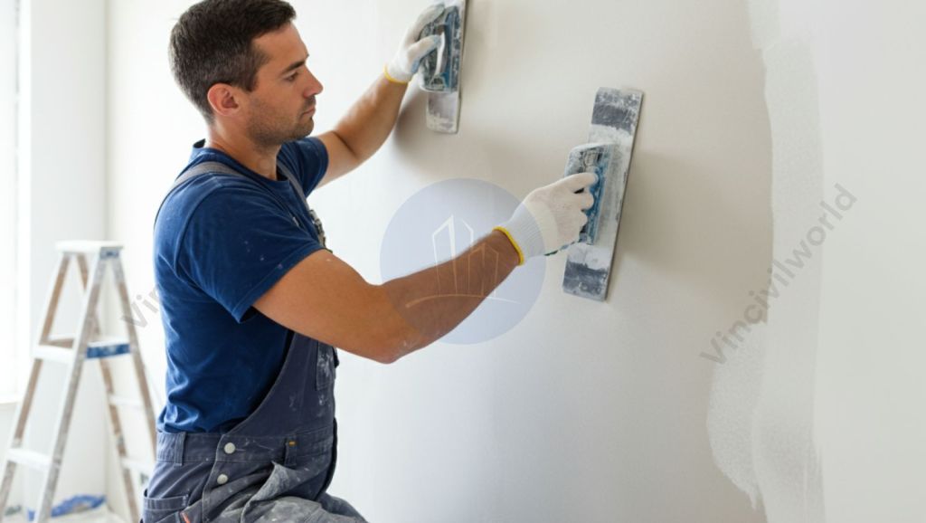
Application and workability
| Gypsum plaster | Conventional plaster |
| Gypsum plaster is available in ready mix form in bags. The dry powder is mixed with water in the recommended proportions. | Cement sand plaster uses sand available as loose and to be conveyed and screened before use. |
| Carrying of bags are easy and convenient between floors. | Carrying loose sand is not easy and requires more labour and time. |
| Factory mixed and maintains accuracy in proportions | Site mixing of cement sand is done manually by laborers and very difficult to maintain the proportions and accuracy |
| Gypsum plaster is light and can be easily applied to the wall and finished. | Application of cement plaster requires skilled masons and no so easy compared with gypsum plaster. |
| Gypsum plaster is easy to level and finish and adheres easily to smooth as well as rough surfaces. | Cement plaster needs more time. Skilled masons are required to attain a smooth and even finish. Applying plaster to smooth surfaces is very difficult. |
| The same gypsum plaster is used for AAC Blocks, brickwork, flyash bricks, concrete blocks, and CLC blocks. | Cement plaster ingredients are changed with the surface. |
Mixing and application of gypsum plaster are very easy with minimal involvement of labour. Gypsum plaster can eliminate unskilled laborers involved in the mixing and carrying of mortar. The productivity of gypsum plaster is much higher than that of conventional plaster. These factors can drastically decrease the labour cost and maintain quality at the site.
High Productivity
Per mason, productivity is high compared to conventional plaster. Finishing of gypsum plaster to the required finish level is comparatively easy in the case of gypsum plaster.

Curing and water wastage
Mixing of gypsum requires minimal water wherein cement plaster requires more water for the mixing and curing process. Cement plaster requires mandatory water curing to avoid shrinkage cracks and requires a large amount of water and wastage of water. Cement plastering and curing is very difficult in areas where there is a scarcity of water.
Wastage and house keeping
| Gypsum plaster | Conventional Plaster |
| Gypsum plaster generates less wastage and the area looks clean and no major housekeeping or removal of debris is required. This can save substantial housekeeping labour. | Plastering generates wastage in terms of mortar, cement, sand, and water. |
Strength and durability
| Gypsum plaster | Conventional Plaster |
| Excellent high strength after drying. They are durable and light weight. Hence reduces the dead loads on the structure. | Cement plaster density is more and increase the dead loads on the structure. |
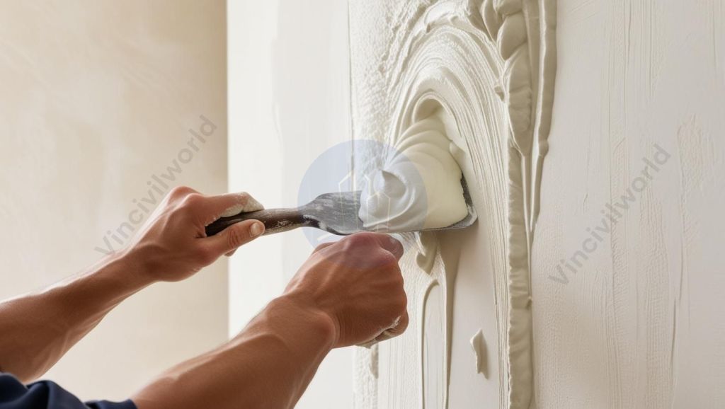
Quality of finish
| Smooth Finish, Perfectly lined, leveled smooth walls and perfect right-angled corners. | Plastering gives a rough finish and needs another coat of putty/POP for making it level and smooth for paint finishes. |
| A very thin coat of putty/POP is required for producing a perfect interior finish. | A minimum of 6 mm thickness of POP must be applied. Alternatively, layers of putty should be applied. This process makes the surface smooth enough to receive the paint finish. |
Environmental friendly and Green Building material.
| Gypsum plaster | Conventional plaster |
| Gypsum is a naturally obtained material and gets deposited frequently on the lake and seawater. The depletion of the resource may not happen in the case of gypsum and is an environmentally friendly material. Gypsum does not emit any VOC s (hazardous materials) and is safe. | Sand obtained from river beds is used for plastering. The sand sources are getting eliminated due to environmental issues and government bans. The availability of good quality sand and is also a very big issue. |
| Gypsum plaster is environmental friendly and green product. | Cement plaster is not a green product |
Acoustic properties
Gypsum plastered surface posses very good acoustic properties and echos are eliminated. Cement plastered surfaces need to be applied with costly acoustic materials to make it soundproof.
Fire resistant
Gypsum plaster is highly resistant to fire where as plaster become brittle and de-bonds from the surface on fire.
Thermal conductivity
Gypsum plastered rooms are comparatively cooler than cement plastered walls due to high thermal conductivity. This can reduce Air condition loads and reduce energy bills.
Economical product
Due to the scarcity of sand and increased costs Gypsum plaster is tuning out to be a very cost-effective option. Gypsum is very easy to mix and place. It eliminates labour charges incurred for mixing raw materials and curing. It also minimizes wastage, making gypsum a very economical product compared to conventional plaster.
Conventional plaster needs a thick layer of POP or putty over it to produce a smooth, seamless, and fine finish whereas gypsum plaster can even be directly painted. But a fine coat of surface coat is always recommended for gypsum plaster for a perfect finish.
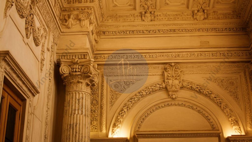
Gypsum plaster can also be used for decorative applications. The space looks big and elegant after plastering with gypsum plaster.
Rust inhibitor & anti fungal
Gypsum plaster is a rust inhibitor where as cement plaster is not. Gypsum plaster got anti fungal properties.
Disadvantages of Gypsum plaster
Gypsum plaster has some major disadvantages compared to conventional plaster.
External applications
Gypsum plaster cannot be used for external applications and areas prone to water or moisture like bathrooms, kitchen etc.
Gypsum plaster material is costly. However, compared to the other factors that are eliminated while using gypsum, it turns out to be far more economical. It is a more economical product compared to conventional plaster.
Conclusion
After going through the following factors we can say gypsum plaster is a clear winner.
Gypsum plaster is an environment-friendly, cost-effective, lightweight, and durable material. They are flame retardant and got high coverage material with easy application. Gypsum plaster is thermal resistant and acoustic materials that can produce beautiful and elegant surfaces. They can retain any type of finishes and coats and maintain the charm and sheen for years.