A cable stayed bridge is a modern engineering marvel known for its strength, efficiency, and aesthetic appeal. It uses one or more towers to support the bridge deck through a series of cables, which transfer the load directly to the foundation. Unlike suspension bridges, the cables in a cable stayed bridge connect directly from the deck to the towers in a straight line. This design provides greater rigidity, making it ideal for long spans and challenging terrain.
Cable stayed bridges are widely used for highway crossings, urban connections, and river spans due to their cost-effectiveness and adaptability. The distinctive arrangement of cable-stayed bridge cables creates visually striking structures that enhance the skyline. Some famous cable-stayed bridge examples include the Millau Viaduct in France and the Russky Bridge in Russia. With their efficient load distribution and elegant design, cable-stayed bridges continue to shape modern infrastructure globally.
In this article, we will explore the key components, types, and advantages of a cable-stayed bridge. We’ll also explain how cable stayed bridge cables function, discuss various construction techniques, and highlight notable cable-stayed bridge examples. By the end, you’ll understand why this design is widely used in modern infrastructure projects.
- What is a Cable-Stayed Bridge?
- How Does a Cable-Stayed Bridge Work?
- Key Components of a Cable-Stayed Bridge
- Types of Cable-Stayed Bridges
- Advantages of Cable-Stayed Bridges
- Challenges and Limitations of Cable-Stayed Bridges
- Construction Techniques for Cable-Stayed Bridges
- Comparison Between Cable-Stayed and Suspension Bridges
- Famous Examples of Cable-Stayed Bridges Around the World
- Applications of Cable-Stayed Bridges in Modern Infrastructure
- The Future of Cable-Stayed Bridges
- Key takeaways
- Conclusion
What is a Cable-Stayed Bridge?
A cable-stayed bridge is a type of bridge where the deck is directly supported by cables connected to one or more towers/ pylons . The towers bear the load, and the cables transfer the weight to the foundation, creating a balanced and efficient structure. Unlike suspension bridges, where cables run horizontally between towers, cable-stayed bridge cables are attached directly from the deck to the tower in a straight or fan-like arrangement. This design provides superior stiffness and requires less material, making it cost-effective and suitable for long spans.

Cable-stayed bridges are common in modern infrastructure due to their strength and aesthetic appeal. In India, the Bandra-Worli Sea Link serves as a well-known example of this type of bridge. It showcases the country’s advancements in bridge engineering. Other famous cable-stayed bridge examples include the Sutong Bridge in China and the Øresund Bridge connecting Denmark and Sweden. These bridges exemplify their efficiency in various applications.
How Does a Cable-Stayed Bridge Work?
A cable-stayed bridge works by using a combination of towers (pylons) and stay cables to support the bridge deck. The towers, which are vertical structures, act as the primary load-bearing elements. Stay cables run directly from the towers to the deck in either fan, harp, or radial patterns. These patterns distribute the weight of the bridge and its traffic evenly.
The cables are tensioned to hold up the deck. They transfer the weight from the deck to the towers. The towers then channel the load down to the foundation. This design allows the bridge to span long distances without the need for additional piers. This makes it efficient and cost-effective for crossing large bodies of water or valleys. The tension in the cables and the compression in the towers create a balanced system. It allows the cable-stayed bridge to remain stable under heavy loads. This includes traffic, wind, and environmental stresses.
Key Components of a Cable-Stayed Bridge
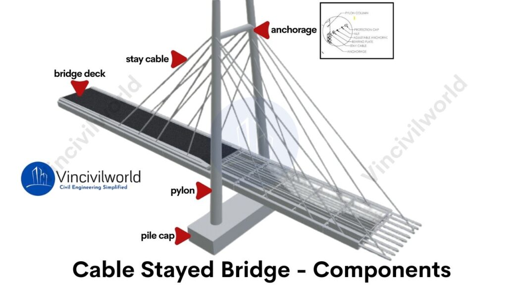
A cable-stayed bridge consists of several essential components that work together to create a stable and efficient structure. Each part plays a crucial role in supporting the deck and transferring the load through the cable-stayed bridge cables. Below are the key components:
- Towers/Pylons
- Stay Cables
- Deck Structure
- Anchorages
Towers/Pylons
Towers, also known as pylons, are the vertical structures that support the cable-stayed bridge cables. They carry the majority of the load by transferring it to the foundations. Towers are usually made of concrete or steel, depending on the bridge design. A well-known example is the Bandra-Worli Sea Link in India, where towering pylons define its unique structure.
Types of Towers (Pylons)
Cable-stayed bridge towers come in various shapes based on design needs and aesthetics. Common types include A-shaped, H-shaped, and single-column towers. A-shaped towers, like those seen in the Bandra-Worli Sea Link in India, provide stability for long spans. H-shaped towers offer simplicity and strength, while single-column towers are ideal for minimalist designs. These towers bear the load of the thereby ensuring the structure’s integrity.
Stay Cables
Stay cables are the cables that directly connect the deck to the towers. These cables carry the weight of the bridge deck and the traffic. In cable-stayed bridges, the cables are arranged in different patterns, like fan or harp styles. These cables allow for flexibility and strength, ensuring the stability of the bridge.
These cables are typically made of high-strength steel strands or parallel wire strands for durability. Stay cables are encased in plastic sheaths to protect against corrosion. They are then grouted with special materials. This process further increases their lifespan and resistance to environmental damage.
Types of Stay Cables
Stay cables are arranged in different patterns, depending on the bridge design. The main types include fan-shaped, harp-shaped, and radial. In fan-shaped designs, the cables spread out from a single point at the top of the tower. In harp-shaped designs, the cables run parallel, creating a clean, sleek appearance. Radial patterns are used for smaller spans, with cable-stayed bridge cables directly supporting the deck.
Deck Structure
The deck structure forms the road or walkway of the cable-stayed bridge. It is supported by the stay cables and often consists of steel or reinforced concrete. The deck must distribute the load evenly across the bridge. In many cable-stayed bridges in India, the deck is designed to handle heavy vehicular traffic. It can also withstand environmental conditions.
Types of Deck Structures
Decks in cable-stayed bridges can be constructed using steel, concrete, or composite materials. Concrete decks are heavy but offer high durability, while steel decks are lighter, making them suitable for longer spans. Composite decks, combining steel and concrete, offer the best of both worlds, balancing weight and strength. The deck structure must efficiently transfer loads to the stay cables and towers.
Decks in cable-stayed bridges can be constructed using steel, concrete, or composite materials. Concrete decks are heavy but offer high durability, while steel decks are lighter, making them suitable for longer spans. Composite decks, combining steel and concrete, offer the best of both worlds, balancing weight and strength. The deck structure must efficiently transfer loads to the stay cables and towers.
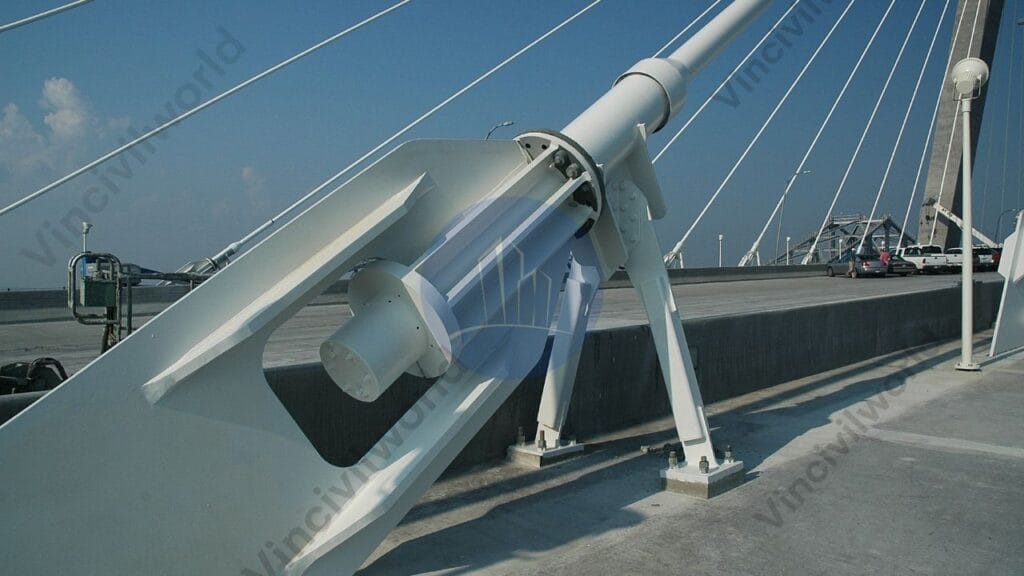
Anchorages
Anchorages are crucial in securing the stay cables to the deck and the towers. They ensure that the load is evenly transferred and that the cables remain in tension. Proper anchorage design is vital to prevent movement in the cables, ensuring the bridge’s durability and long-term stability.
Types of Anchorages
Anchorages are essential for securing the stay cables to the deck and towers. The two main types are external and internal anchorages. Inspecting and maintaining external anchorages is simpler due to their visibility, while embedding internal anchorages within the deck or tower offers added protection. Both types ensure the cable-stayed bridge maintains its tension and stability under varying loads.
Types of Cable-Stayed Bridges
Cable stayed bridges are classified based on the following basis
- Based on the Arrangement of Pylons
- Based on the shape of Pylons
- Based on Cable Arrangements
Based on the Arrangement of Pylons
Cable-stayed bridges can be classified by the arrangement of pylons (towers) used to support the deck. The most common types include single-pylon bridges. They have a central tower supporting cables that radiate outward. There are also double pylon bridges and multiple-pylon bridges, which feature two or more pylons placed along the bridge deck. Another variation is asymmetric pylon bridges. The pylons are of different heights or placed off-center. This accommodates specific design needs or terrain constraints.
Multiple-Tower
Multiple-tower cable-stayed bridges use two or more pylons to support longer spans. Engineers often use this type of bridge for large river crossings. These areas require extensive span coverage. Multiple towers distribute the load across a larger area.
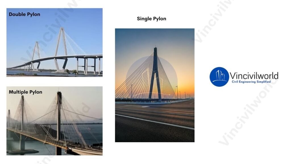
Single-Tower
Single-tower cable-stayed bridges feature a single pylon or tower that supports the entire bridge structure. Consequently, narrow waterways or urban environments with limited space are ideal for these bridges. In addition, they provide a sleek and minimalist design.
Double Pylons
Based on the shape of Pylons
- H-Shaped Pylons: These pylons feature two vertical legs. A horizontal beam connects them at the top. This design offers high stability and evenly distributes forces.
- A-Shaped Pylons: The pylons are tapered at the top. They resemble the letter “A,” which gives a more streamlined appearance. This design efficiently channels forces down the legs.
- Diamond-Shaped Pylons: These pylons are wider at the base and converge near the top, forming a diamond shape. They offer a unique aesthetic and strong structural support.
- Y-Shaped Pylons: These pylons resemble the letter “Y.” They have a single leg splitting into two arms at the top. This design offers both flexibility and strength.
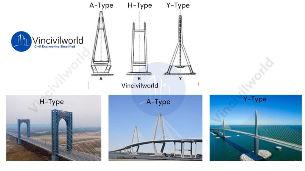
Each shape provides distinct structural advantages. The choice depends on the specific needs of the bridge design, aesthetics, and load distribution requirements.
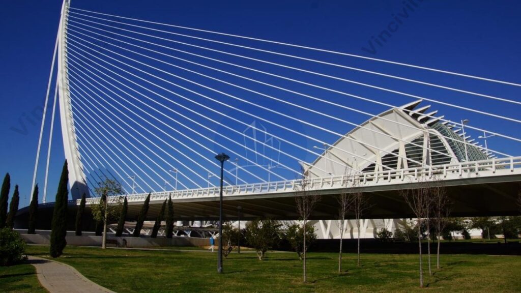
Based on Cable Arrangements
Cable arrangements in cable-stayed bridges generally follow three main patterns:
- Radial (fan): Cables radiate from the top of the pylon to various points along the deck, creating a fan-like pattern.
- Parallel (harp): Cables are attached at regular intervals along the pylon and deck, forming a parallel arrangement.
- Semi-fan: A hybrid design where cables partially fan out but with more uniform spacing, balancing aesthetics and structural efficiency.
Radial Pattern
The cables radiate outward from the pylon to the deck, forming a fan-like shape. This arrangement offers efficient load distribution.
Harp/parallel Pattern
The cables are arranged in a parallel pattern, resembling the strings of a harp. This configuration is commonly used for bridges with a central pylon
Fan Pattern
In a fan pattern, stay cables converge at the top of the tower, spreading out to the deck in a fan-like arrangement. Engineers commonly use this design for cable-stayed bridges with shorter spans, offering both strength and visual distinction.
Advantages of Cable-Stayed Bridges
Cable-stayed bridges offer numerous benefits due to their efficient design and versatility. Moreover, they are ideal for long spans and challenging terrains, as they provide both structural stability and aesthetic appeal. Below are the key advantages:
Fast Construction
The modular construction process of cable-stayed bridges allows for quicker building, reducing disruptions to surrounding areas and environments.
Cost-Effective Construction
Cable-stayed bridges use fewer materials. They require less maintenance compared to suspension bridges. This results in lower construction costs and long-term maintenance costs.
Efficient Load Distribution
Stay cables directly transfer the deck’s load to the towers. This reduces the need for multiple support piers. It simplifies construction and allows for longer spans.
Versatile Design
Cable-stayed bridges offer flexibility in design. They adapt to different structural and architectural needs through various cable arrangements. These arrangements include fan, harp, or radial patterns.
Aesthetic Appeal
The visible arrangement of cable-stayed bridge cables creates a striking, modern look. It enhances the visual landscape of urban or natural settings.
Challenges and Limitations of Cable-Stayed Bridges
While cable-stayed bridges offer many advantages, they also come with certain challenges that impact their design, construction, and long-term performance.
Complex Construction Techniques
Building cable-stayed bridges requires specialized engineering knowledge and equipment. The tensioning of cables, alignment of towers, and precision needed for the cable-stayed bridge cables require high-level expertise. This expertise can increase the complexity and cost of construction.
Maintenance Requirements
Although durable, cable-stayed bridges require regular inspections and maintenance, particularly for the stay cables. Environmental factors like corrosion and wind-induced vibrations can affect cable performance. These issues lead to increased maintenance efforts. This ensures the long-term stability of the structure.
Wind and Seismic Vulnerability
They are sensitive to strong winds and seismic activity. The flexibility of the cables can lead to vibrations or oscillations. If not managed through proper dampening systems, these vibrations may compromise the structure’s stability during severe weather or earthquakes.
Accumulation of snow
The cable-stayed bridges will accumulate ice due to environmental conditions. This ice will cause great harm to the traffic safety below the bridges.
High Initial Costs
These structures are generally cost-effective in the long run. However, they can incur high initial construction costs. This is due to the specialized materials and engineering that they require. The use of advanced materials for stay cables and pylons adds to the upfront expense of the project.
Construction Techniques for Cable-Stayed Bridges
Cable-stayed bridges require precise construction techniques to ensure structural integrity and stability. The process begins with the construction of the towers, which are the main vertical supports. These towers must be strong enough to handle the immense forces transmitted by the cables. Once the towers are in place, deck sections are incrementally installed, typically using a cantilever method. This involves placing deck segments starting from the towers and progressing outward in both directions to maintain balance.
The construction team anchors the cables to the deck and tower, supporting the deck as the build progresses. They continuously adjust the cable tension to ensure the deck stays level. High-strength steel cables are essential. They transfer the load from the deck to the towers. This reduces bending moments in the deck structure.
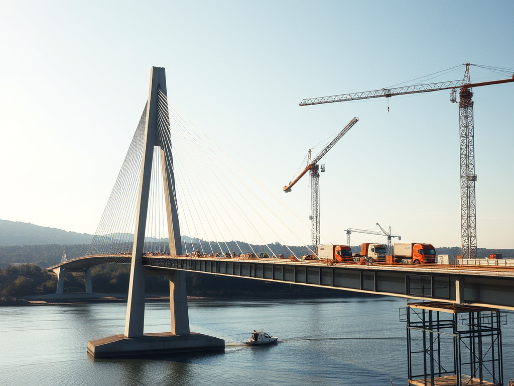
The construction process also requires careful consideration of material properties and cable tension forces, with adjustments often calculated using advanced methods like finite element analysis. Designers must give the bridge deck high torsional rigidity to resist twisting forces caused by uneven loads, ensuring long-term durability. Regular monitoring and adjustments during the construction phases are critical to maintaining the bridge’s alignment and stability
Comparison Between Cable-Stayed and Suspension Bridges
| Feature | Cable-Stayed Bridges | Suspension Bridges |
|---|---|---|
| Structural Design | Cables directly connect the deck to the towers. | Cables run from towers to anchorages, supporting the deck via smaller vertical cables. |
| Main Cables | Fewer, shorter cables, anchored directly to the towers. | Long, continuous cables running over towers, anchored at both ends. |
| Cable Arrangement | Radial or fan-shaped pattern from towers to deck. | Vertical hangers suspend the deck from main cables. |
| Tower Height | Towers are shorter compared to suspension bridges. | Taller towers are required to support the long, continuous main cables. |
| Span Length | Best suited for medium spans (typically 200 to 1,000 meters). | Suitable for long spans (over 1,000 meters). |
| Construction Method | Faster to build as deck sections and cables are installed incrementally. | Requires extensive anchoring and time-consuming construction, especially for long spans. |
| Deck Support | Cables directly support the deck, providing greater stiffness. | The deck is supported by vertical hangers, allowing for more flexibility. |
| Torsional Stiffness | Higher torsional stiffness, making it less prone to twisting under loads. | Lower torsional stiffness, making it more flexible and vulnerable to twisting. |
| Cost | Generally more economical for medium spans. | Higher construction costs, particularly for long spans. |
| Maintenance | Lower maintenance costs due to fewer cables and less complex structure. | Higher maintenance costs due to more extensive cable systems and anchorages. |
| Aesthetics | Modern, sleek appearance with visible cables fanning from the towers. | Iconic and graceful with sweeping main cables and vertical hangers. |
| Examples | Millau Viaduct (France), Vasco da Gama Bridge (Portugal) | Golden Gate Bridge (USA), Akashi Kaikyō Bridge (Japan) |
This comparison highlights the key differences in design, function, and applications between cable-stayed and suspension bridges
Famous Examples of Cable-Stayed Bridges Around the World
Here’s a list of famous cable stayed bridges around the world:
- Millau Viaduct (France) – One of the tallest bridges globally, known for its elegance and engineering.
- Vasco da Gama Bridge (Portugal) – The longest bridge in Europe, spanning 12.3 km over the Tagus River.
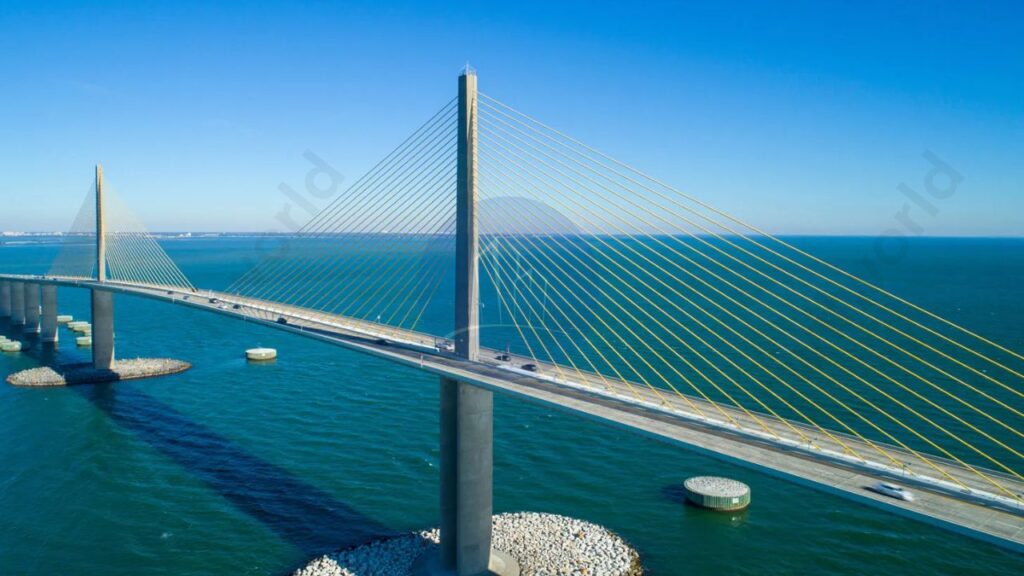
- Sunshine Skyway Bridge (USA) – An iconic cable-stayed bridge in Florida, noted for its striking design.
- Sutong Bridge (China) – Famous for its long span, once the longest cable-stayed span in the world.
- Russky Bridge (Russia) – Holds the record for the longest cable-stayed span, connecting Russky Island to mainland Russia.
These bridges exemplify cutting-edge engineering and aesthetic appeal.

Applications of Cable-Stayed Bridges in Modern Infrastructure
Here’s a list of applications in modern infrastructure:
- Highway Crossings: They efficiently connect major roadways, facilitating smoother traffic flow.
- Railway Bridges: Ideal for spanning railway lines, minimizing disruptions to train services.
- Urban Infrastructure: Often used in city planning to enhance connectivity between districts.
- Waterway Crossings: They provide essential links over rivers and lakes, supporting commercial and recreational navigation.
- Pedestrian and Bicycle Paths: Some designs incorporate dedicated lanes for non-motorized traffic, promoting eco-friendly transport.
- Iconic Landmarks: Their aesthetic appeal makes them popular for constructing visually striking landmarks.
These applications demonstrate the versatility and effectiveness in various infrastructure projects
The Future of Cable-Stayed Bridges
The future of cable-stayed bridges is promising, driven by advancements in materials and engineering techniques. Innovations such as high-strength steel and fiber-reinforced polymers will enhance durability and reduce maintenance costs. Additionally, the integration of smart technologies, like sensors for real-time monitoring, will improve safety and efficiency. As cities continue to expand, cable-stayed bridges will meet infrastructure demands and maintain aesthetic appeal. This makes them increasingly relevant in modern urban planning.
Key takeaways
Here are the key takeaways
- Efficient Load Distribution: They distribute loads effectively through towers and stay cables.
- Aesthetic Appeal: Their unique design contributes to the visual beauty of infrastructure.
- Long Spans: Capable of spanning long distances without multiple piers.
- Cost-Effective Construction: Typically cheaper and quicker to construct compared to other bridge types.
- Key Components:
- Towers: Support the bridge deck.
- Stay Cables: Connect the towers to the deck.
- Deck Structures: The surface of the bridge.
- Anchorages: Secure the cables.
- Configuration Variations: Includes fan, harp, and radial patterns to meet different design requirements.
- Advantages: Faster construction and lower maintenance costs.
- Challenges: Sensitivity to wind and seismic activity.
- Notable Examples: Includes the Millau Viaduct and the Bandra-Worli Sea Link, illustrating their significance in modern infrastructure.
Conclusion
Cable-stayed bridges are remarkable engineering achievements characterized by their efficient load distribution and aesthetic appeal. They use towers to support the bridge deck. A system of stay cables allows for long spans without multiple piers. This design not only enhances structural rigidity but also offers cost-effective construction. Key components include towers, stay cables, deck structures, and anchorages. They come in various configurations such as fan, harp, and radial patterns to suit different needs. Cable-stayed bridges offer advantages like faster construction and lower maintenance costs. However, they also face challenges related to sensitivity to wind and seismic activity. Notable examples include the Millau Viaduct and the Bandra-Worli Sea Link, showcasing their significance in modern infrastructure.