Destructive tests (DT) and Non-destructive tests (DT) are the tests done on hardened concrete. Destructive tests on concrete are essential for determining the strength and durability of hardened concrete. These tests evaluate how concrete performs under stress and give critical data for assessing the quality of a structure.
Destructive concrete testing involves breaking or damaging samples to measure their ultimate strength. Common types of destructive concrete tests include compressive strength tests, split tensile tests, and flexural tests. Testing of hardened concrete ensures that it meets design specifications and structural requirements. These tests for hardened concrete offer reliable insights into performance, making them crucial for quality control in construction. Destructive tests of concrete help identify potential weaknesses, ensuring long-term durability and safety of structures.
Concrete is the oldest and most important construction material in the world. Testing of the concrete plays an important role to know the strength, durability and condition of the structure. This article is about the types of Destructive concrete tests and non-destructive tests done on hardened concrete.
- Types of tests on hardened concrete
- Significance of Destructive tests on hardened Concrete.
- Types of Destructive tests for hardened Concrete
- Key Takeaways
- Conclusion
Types of tests on hardened concrete
Tests on hardened concrete are classified into two types.
- Non destructive tests (NDT)
- Destructive tests (DT)
This article we will discuss about the Destructive tests on hardened Concrete. For Non destructive tests on Hardened Concrete please refer our article..
Also Read : Non destructive tests on Hardened Concrete.
Destructive tests and Non-Destructive tests are done to determine the important properties of concrete. These properties include but not limited to compressive strength, flexural strength, tensile strength etc.
Destructive tests on Hardened Concrete
The quality of concrete is important for construction. Hardened concrete attains strength as it matures. The destructive test of concrete helps to understand the behavior and quality by breaking the test specimen at certain loads. The primary step of the destructive test is to cast test specimens from freshly made concrete.
The destructive testing method is suitable and economically beneficial for the concrete specimens that are produced at a large scale. The main intention of destructive tests is to investigate the service life. They aim to detect weaknesses in the design that might not show under normal working conditions. It includes methods where the concrete specimen is broken so as to determine mechanical properties i.e. hardness and strength. This type of testing is very easy to carry out, easier to interpret, and yields more information.
Also read : Concrete mixing – Types and objectives
Significance of Destructive tests on hardened Concrete.
Concrete is a basic construction material, So it should be capable to withstand heavy loads. The concrete test results mainly depend on the cement strength, water-cement ratio, concrete quality etc. The main objectives of the hardened concrete test are as follows.
- Quality control
- Acceptance of concrete
- Evaluation of curing
- To provide information on the use of sand and aggregate.
- For evaluating the uniformity of concrete
- Estimates the concrete quality with standard requirements.
- To determine the uniform stress distribution.
- Investigating the behavior of concrete.
- For determining the in-place concrete strength.
- Age of concrete, etc.

Types of Destructive tests for hardened Concrete
The main intention of destructive tests is to investigate the service life. They aim to detect the weakness of design that might not show under normal working conditions. These tests determine the compressive, flexural and tensile strength of concrete. There are different types of tests available to examine the hardened concrete. They are as follows.
- Compressive strength test
- Splitting tensile strength test
- Flexural strength test
This article focuses on Compressive strength test and Flexural Strength test on Hardened Concrete . For splitting tensile strength test please refer to our article mentioned below.
Also Read : Splitting Tensile Strength Test on Hardened Concrete
Compressive strength test of concrete
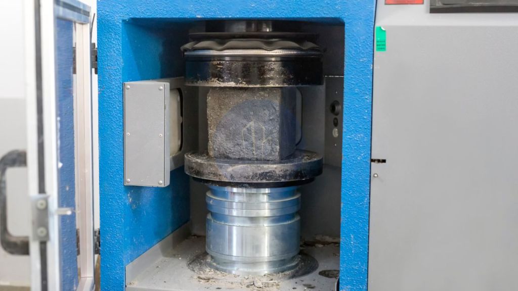
The compressive strength test of concrete is a crucial method in destructive concrete testing. It assesses how much load a concrete sample can withstand before failure. In this test, hardened concrete specimens are subjected to increasing pressure until they crack. This test helps evaluate the structural integrity of the concrete. As a major type of destructive concrete test, it offers vital data. This ensures the quality and performance of concrete in various construction applications.
Compressive strength of concrete is the ability of the concrete to withstand loads without cracking or deformation. The concrete specimen to conduct this test should be either cylindrical or cubic. The apparatus for performing this test is a Compression testing machine. The relevant IS code for this test is IS 516-1959. The load at which the specimen fails measures its strength.
Compressive strength of the concrete = Load at which the concrete breaks / Cross-sectional area of the specimen
The unit of compressive strength of concrete is N/mm^2. The test should be done at 7, 14 & 28 days.
For more details : Compressive strength of concrete -significance and test procedure

Splitting tensile strength test on hardened Concrete
The splitting tensile strength test is one of the tests on hardened concrete for determining its tensile strength. Concrete is a durable construction material. Under tension, concrete is brittle in nature. Therefore it causes cracks and deteriorates. The splitting tensile strength test measures the concrete tensile strength. For this test, we use cylindrical specimens with 150 mm diameter and 300 mm height.
The tensile strength of concrete is
Splitting tensile strength of concrete, T= 2P/ Ω LD
The unit of tensile strength is N/mm. The IS 5816: 1999, ASTM C496 gives the standard aspects for this test.
Also Read : Splitting tensile strength test on concrete- Significance and test procedure
Flexural strength test
The flexural strength test and splitting tensile strength test are almost the same. Because both the tests measure the tensile strength of concrete. The flexural strength test of concrete measures the tensile strength of concrete through an indirect method. The relevant codes for this test are ASTM C293 & ASTM C78. This test measures the ability of concrete to resist failure in bending. The modulus of rupture is the measure of tensile strength. Its unit is MPa or psi.
Modulus of rupture, MR = 3PL/ 2bd^2
Where,
P is the Ultimate applied load, L is the span length, b & d is the average width and depth of specimen at fracture.
Key Takeaways
- Destructive tests on hardened concrete help assess strength and durability.
- Compressive strength test is the most common destructive concrete testing method, crucial for evaluating load-bearing capacity.
- Split tensile strength tests measure concrete’s resistance to tension.
- Flexural strength tests assess concrete’s ability to resist bending, providing data on tensile strength.
- Testing of hardened concrete is vital for ensuring the quality and performance of concrete in construction.
- The results from tests for hardened concrete offer insights into the structural integrity of concrete elements.
Conclusion
Destructive tests on hardened concrete are critical for assessing the strength, durability, and performance of concrete structures. Methods like the compressive strength test, splitting tensile test, and flexural strength test provide valuable data. They show how concrete will perform under different stresses. These types of destructive concrete tests identify weaknesses that may not be visible under normal conditions. This ensures the long-term stability and safety of concrete structures. Destructive concrete testing provides essential insights into the quality of the material. It subjects samples to failure. This supports better design and construction practices.
These are the major tests done on hardened concrete for determining the strength of concrete. As concrete is the basic ingredient of all structures , the quality has to be ensured to maintain the structural stability and life.