Specific gravity and water absorption test are significant tests on aggregates. Perhaps aggregates are the fundamental and essential components of concrete and play a significant role in the design mix of concrete. More than 70 to 80 per cent of the volume of concrete is aggregate. Hence the water absorption and specific gravity test are essential and significant tests .
The specific gravity test of aggregates is a crucial procedure in construction and materials engineering. This test measures the density of aggregates, which helps decide their quality and suitability for construction. Specifically, the specific gravity for coarse aggregate is essential for mix design and ensuring structural stability. Additionally, the specific gravity test of aggregate provides valuable data for comparing different materials. Alongside this, the water absorption test is vital. It measures how much water aggregates absorb, which affects their performance in concrete. The water absorption formula calculates the amount of water absorbed relative to the aggregate’s weight. Both the specific gravity and water absorption tests are critical. These tests assess aggregate properties and ensure the durability of construction materials.
The specific gravity is the measure of strength of aggregates, while water absorption indicates the porosity of aggregates.
- Specific Gravity Tests on Aggregates
- Specific gravity test on aggregates
- Water absorption test on aggregates
- Specific gravity test on aggregates
- Key Takeaways
- Conclusion
Specific Gravity Tests on Aggregates
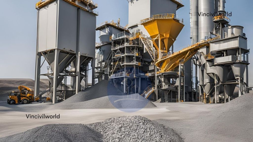
Aggregates are the second major ingredient of concrete that contributes around 60 to 70% of its volume. One of the major contributing factors to the concrete quality is the quality of aggregates used therein. The test methods of aggregates are done as per IS 2386 part-4 assists in assessing the quality of aggregates. Following are the tests for analyzing the quality of aggregate.
- Aggregate Crushing test
- Abrasion test
- Soundness test on aggregate
- Impact test
- Shape test
- Water absorption test
- Bulk specific gravity test
This article is about Specific Gravity and Water absorption test on Aggregate.
Also Read : Quality tests to be done on Concrete
Also Read : Bitumen – 9 quality tests on bitumen
Specific gravity test on aggregates
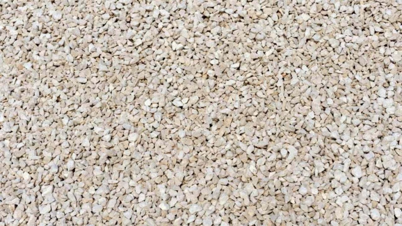
The specific gravity test of aggregate is crucial for assessing the density and quality of aggregates used in construction. This test evaluates the ratio of the weight of the aggregate to the weight of an equal volume of water. It is essential for both fine and coarse aggregates, providing insights into their suitability for various applications. The specific gravity for coarse aggregate, in particular, impacts the mix design and overall performance of concrete. Precise results from the specific gravity test of aggregates help guarantee that the concrete achieves the desired strength and durability. Proper understanding of these tests is vital for effective construction practices.
The specific gravity is an indirect measure of the strength of aggregate. Through this test, the general identification of the aggregate becomes easier. Low specific gravity aggregates are weak. Hence, they are not suitable for construction.
Water absorption test on aggregates
The water absorption test on aggregates measures how much water an aggregate can absorb. This impacts the strength and durability of concrete. This test is crucial for determining the porosity of the aggregate and its ability to retain moisture. To conduct the water absorption test, aggregates are first weighed dry and then submerged in water until they reach saturation. The water absorption formula calculates the percentage of water absorbed by comparing the saturated weight to the dry weight. Accurate water absorption test results ensure proper mix design. They also predict concrete performance. This makes it a key factor in construction quality control.
Water absorption of aggregate measures the weather resistance. It is the percentage of water the aggregate absorbs when immersed in water. The test method for specific gravity and water absorption test is as follows.
Specific gravity test on aggregates
Relevant IS code:
- IS:2386(Part 4)-1963
Apparatus used:
- Weighing machine
- Drying oven
- Wire mesh
- Container

Test procedure of Specific gravity test of aggregates
- For this test, take about 2000g of aggregate and wash them thoroughly with water.
- Remove the fine particles and dust, then drain the water and place them in the wire basket.
- Then immerse this in distilled water with a temperature between 22 and 32 degree Celsius for 24 hours.
- Then Weigh the basket with aggregates and record them as A1.
- After 24 hours, remove the aggregates from the mesh and weigh them as A2.
- Then drain the water from the aggregate and Again weigh the dried aggregate. B
- Place the sample in the dry oven for 24 hours. after the oven drying weighs them and record as C.
- Now calculate the specific gravity and water absorption of the aggregate using the given formula.
Specific gravity = C / (B- A)
Water absorption = {(B-C)/C} * 100
where, A= A1 – A2, ie weight of the saturated aggregate in water
B = weight of drained aggregate
C = weight of oven-dried aggregate.
Aggregate with high specific gravity has good strength. The normal value of specific gravity is 2.5 to 3.0. The water absorption should not exceed 0.6%. Thus this test helps to determine the quality, strength and water absorption.
Water absorption test of aggregates – Test procedure
The procedure is same as specific gravity of aggregates. The water absorption should not exceed 0.6%. Thus this test helps to find the quality, strength and water absorption.
Key Takeaways
The specific gravity test of aggregate is essential in determining the strength and quality of aggregates. It provides critical information for construction mix designs and ensures structural stability. Specifically, the specific gravity for coarse aggregate influences the mix design and overall concrete performance. The water absorption test evaluates how much water an aggregate absorbs, affecting its durability. The water absorption formula helps calculate the water retained by aggregates, influencing mix design accuracy. Both the specific gravity test of aggregate and the water absorption test are vital in assessing aggregate properties. They guarantee that materials meet the required standards for construction durability.
Conclusion
The specific gravity test of aggregate is critical in determining the quality of aggregates in construction. The water absorption test is also crucial for assessing the suitability of aggregates. The specific gravity for coarse aggregate is a key parameter for concrete mix design, ensuring strength and structural integrity. Precise testing of specific gravity of aggregates helps predict performance and durability. On the other hand, the water absorption test assesses the porosity of aggregates. The water absorption formula determines the percentage of water absorbed. These tests are crucial for ensuring that aggregates meet the required standards. They give essential data for achieving high-quality, durable concrete structures.