Chain Surveying Procedure forms the backbone of basic land measurement techniques used in civil engineering projects. This traditional method relies on linear measurements to establish accurate ground layouts for small and relatively level areas. The chain surveying method is simple, cost-effective, and ideal where high precision instruments are unnecessary. Understanding the procedure of chain surveying helps engineers and students grasp how baseline measurement, ranging, and offsetting work together to map land efficiently. Widely applied as a chain survey in civil engineering, it is especially useful for preliminary surveys and boundary demarcation. The chain surveying advantages include ease of execution, minimal equipment requirements, and suitability for open terrains. This article explains the complete procedure and highlights the practical advantages of chain surveying in a clear and systematic manner.
Chain surveying is a widely popular method of surveying owing to its simplicity. Also, if the analysis is done carefully, it produces reasonably reliable results.
In the previous blog, we had shown you the Principle of Surveying in detail. Today, I will take you through the step by step procedure of conducting a chain survey. Let’s begin by discussing what is chain surveying.
Also read : Total station – Principles and fundamentals
- What is chain survey in civil engineering
- Chain Surveying Procedure
- Advantages of Chain Surveying method
- Disadvantages of Chain surveying method
- Key Takeaways
- Conclusion
What is chain survey in civil engineering
Chain survey in civil engineering is a basic land surveying method used to measure distances directly on the ground using a chain or measuring tape. This technique works best for small, open, and fairly level areas where high precision instruments are not required. The method involves creating a framework of straight lines and taking linear measurements with simple tools. Because of its simplicity and low cost, it is widely used for preliminary surveys, boundary marking, and layout work. Chain surveying helps engineers understand site dimensions accurately and provides a foundation for planning and design in construction projects.
Chain surveying is a form of surveying that takes only linear measurements in the field; therefore, it is suitable for surveying small areas with clear details and relatively flat terrain. Moreover, the method derives its name from the chain, which is the most commonly used measuring instrument.
Chain Surveying Procedure
Chain Surveying Procedure begins with a systematic approach to measure land using linear distances only. Before starting the actual measurements, proper planning and site inspection are essential; moreover, a clear understanding of the procedure ensures accuracy, efficiency, and reliable survey results, especially for small and level areas.
Before going to the detailed procedure let’s first understand the instruments used in chain surveying.
Chain Surveying Instruments
- Chain or Tape
- Arrows (Arrows in Surveying).
- Pegs.
- Offset Rods.
- Range Rod (Ranging Rod).
- Offset Rods.
- Hammer.

Also Read : Applications of GPS – 6 Amazing applications unlocked.
Detailed Procedure of Chain Surveying
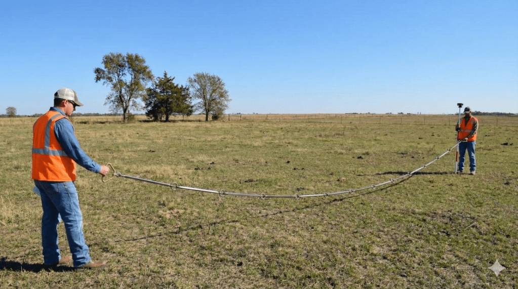
- A chain is used by two men to determine the distance between two points, A and B, in chain surveying.
- The forerunner (leader) is the man who holds the forward end of the chain and pushes it ahead, while the back end man (follower) pulls the chain backward and remains at the starting point.
- During the procedure of chain surveying, the leader carries a ranging rod and ten arrows to mark each full chain length on the ground.
- The follower holds the rear chain handle firmly by fixing the knob into the groove of the handle.
- The follower places the handle near the heel of the foot and drags the chain from the forearm position to bring it perpendicular to the survey line AB.
- The leader then moves the chain left or right based on signals from the follower until the chain lies exactly on the straight line joining points A and B.
- When the chain aligns correctly, the leader points the forearm toward the ground and forms two intersecting lines using the ranging rod.
- The leader then grips the chain handle with both hands and lifts it slightly to ensure it is perfectly horizontal and clear of ground obstacles.
- After this, the leader places one arrow from the set of ten into the semicircular groove on the outside of the chain handle.
- The arrows indicate the completion of one full chain length.
- After placing the arrow, the leader advances forward and pushes the chain ahead.
- The leader stops at the next arrow position and waits there.
- The arrow placed in the groove of the chain handle helps keep the handle fixed securely.
Procedure for chain surveying
- This positioning ensures the handle fits between the legs of the follower and aligns the forearm correctly with the survey line AB.
- The leader straightens the chain carefully and halts at the correct position.
- The leader moves the arrow in the same manner as previously described.
- Before the follower advances, the leader pushes the chain forward, and the follower picks up the arrow placed on the ground.
- The survey team repeats this measuring process continuously until they reach end point B.
- At the start of the measurement, the surveyor issues ten arrows to the leader.
- As the follower picks up each arrow, the total number of arrows in use always remains ten, ensuring accuracy in counting chain lengths.
- Since the number of arrows transferred represents the number of full chain lengths measured, there is no chance of forgetting the total measured distance.
- The surveyor determines the total length of the survey line by counting the number of chain lengths indicated by the arrows handed over to the follower.
- When the follower receives all ten arrows, the surveyor records the covered distance in the field book and communicates it to the leader.
- If line AB measures less than one full chain, the surveyor measures the remaining distance carefully using chain links.
- The surveyor reads this partial length directly from the chain and records it accurately in the field book.
- During distance measurement, the surveyor draws necessary sketches and properly notes all measured values.
- The follower not only holds the chain but also ensures correct alignment, accuracy, and proper recording.
- Therefore, experienced and intelligent surveyors should undertake the role of the follower in the chain surveying procedure.

Advantages of Chain Surveying method
Chain Survey in Civil Engineering is a fundamental surveying technique used to measure land distances accurately using linear measurements, simple instruments, and systematic procedures for small, level areas; therefore, the main advantages of the chain surveying method are as follows.
- Simple and easy to understand method
- Requires minimum and inexpensive equipment
- Suitable for small and fairly level areas
- Easy to perform and does not require skilled labor
- Fieldwork can be completed quickly
- Calculations are simple and straightforward
- Errors are easy to detect and rectify
- Best suited for open areas with clear visibility
- Ideal for preliminary and reconnaissance surveys
- Easy recording and plotting of measured data

Disadvantages of Chain surveying method
- In densely populated areas, a simple chain survey is impossible to perform.
- It is time-consuming.
- When there are raised points between the areas to be surveyed, the chain survey process becomes more difficult.
- While surveying large areas, it is not possible to stretch the chain completely to its full length. The sagging of the chain causes errors in the measurement.
That’s it about Chain Surveying. Hope you found this article insightful.
Key Takeaways
- Chain Surveying Procedure is a simple and systematic approach for measuring land using linear distances; therefore, it is easy to understand and apply.
- The chain surveying method, in general, relies on basic instruments such as chains, arrows, and ranging rods.
- The procedure of chain surveying, moreover, involves alignment, ranging, arrow marking, and proper field booking.
- Consequently, it is most effective for small, open, and fairly level areas with clear visibility.
- In chain survey in civil engineering, this method is commonly used for preliminary surveys and boundary measurements.
- Furthermore, the method is economical and easy to execute with minimal training.
- The main chain surveying advantages include simplicity, low cost, and ease of error detection.
- However, accuracy depends on proper alignment and experienced handling.
- Therefore, it is not suitable for large or obstructed terrains.
- Finally, proper recording ensures reliable and accurate survey data.
Conclusion
The Chain Surveying Procedure remains one of the most fundamental techniques in land measurement due to its simplicity and practicality. The chain surveying method uses direct linear measurements; therefore, it is ideal for small-scale projects where advanced instruments are unnecessary. By following the correct procedure of chain surveying, surveyors can achieve reliable results with minimal resources. In chain survey in civil engineering, this method plays a crucial role in preliminary surveys, layout planning, and boundary demarcation; moreover, the key advantages of chain surveying include low cost, ease of operation, and straightforward calculations. Although it has limitations in accuracy and terrain suitability, chain surveying continues to be valuable for basic surveying needs and educational purposes in civil engineering.