Concrete road construction involves building durable pavements using cement concrete road techniques, which prioritize strength and longevity. This method uses layered systems called concrete road layers, including subgrade, sub-base, base, and surface layers, to ensure stability and load distribution. Unlike asphalt, road construction concrete offers higher resistance to weather, heavy traffic, and wear, reducing long-term maintenance costs. Concrete for road construction is preferred for its sustainability, as it reflects sunlight, lowering urban heat, and uses recyclable materials. A cement concrete road lasts 30–40 years, outperforming flexible pavements in lifespan and cost-effectiveness. Engineers choose concrete road construction for highways and urban roads due to its minimal upkeep and eco-friendly benefits. By optimizing concrete road layers and material quality, this method delivers safer, smoother, and more reliable infrastructure.
This article explores concrete road construction, highlighting its layered design, durability, and sustainability. It explains why cement concrete roads outperform asphalt, offering long-lasting, eco-friendly, and cost-effective solutions for modern infrastructure needs.
- Structural components of Concrete Road Construction
- Types of Concrete Road Pavements
- Advantages of Concrete Roads
- Methods of construction of cement concrete roads
- Steps involved in road construction
- Disadvantages of concrete road construction
- Maintenance Practices for Concrete Roads
- Innovations and Future Trends in Concrete Road Construction
- Key Takeaways
- Conclusion
Structural components of Concrete Road Construction
Concrete road construction relies on a well-structured system of layers to ensure durability and strength. These concrete road layers include the subgrade, sub-base, base course, and concrete slab. Each layer plays a critical role in distributing loads and preventing cracks. Proper road construction concrete techniques ensure the longevity of cement concrete roads, making them ideal for heavy traffic and harsh weather conditions. Let us explain each component in detail.
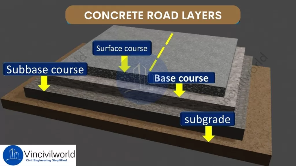
Subgrade
Engineers prepare the native soil to support the road structure, forming the subgrade. In concrete road construction, a stable subgrade is essential as it forms the foundation for all subsequent concrete road layers. Proper compaction of the subgrade prevents settlement and provides uniform support for the road construction concrete. A well-prepared subgrade enhances the durability of the cement concrete road by reducing the risk of cracks and deformations.
Sub-base
Positioned above the subgrade, the sub-base layer consists of granular materials like crushed stone or gravel. In concrete road construction, the sub-base serves to distribute loads and provides additional support to the upper concrete road layers. It also acts as a barrier against moisture, protecting the road construction concrete from potential damage. A properly installed sub-base enhances the overall performance of the cement concrete road.
Base Course
The base course lies directly beneath the concrete slab in concrete road construction. The base course consists of high-quality aggregates that create a stable platform for the pavement. It effectively transmits the loads from traffic to the underlying concrete road. Additionally, the base course plays a crucial role in enhancing the durability and performance of the pavement structure layers. A well-constructed base course is vital for the structural integrity of the cement concrete road, ensuring longevity and durability.
Concrete Slab (Pavement)
The concrete slab, or pavement, is the topmost layer in concrete road construction. This surface layer is made of road construction concrete and is designed to withstand direct traffic loads. The quality of the concrete for road construction used in this layer determines the road’s durability and service life. Proper curing and jointing of the concrete slab are crucial. These practices prevent cracks. They ensure a smooth, long-lasting cement concrete road surface.
Each of these layers is crucial in concrete road construction. They collectively enhance the pavement’s strength. They also improve its durability and longevity. Moreover, proper design and construction of these concrete road layers are essential to ensuring a high-quality cement concrete road. As a result, the pavement can effectively withstand the demands of heavy traffic. It can also endure varying environmental conditions. This ultimately provides a long-lasting and reliable transportation solution.
Types of Concrete Road Pavements
In concrete road construction, selecting the appropriate pavement type is crucial for durability and performance. There are three main types of concrete roads. These are Jointed Plain Concrete Pavement (JPCP), Jointed Reinforced Concrete Pavement (JRCP), and Continuously Reinforced Concrete Pavement (CRCP). Each type utilizes different concrete road layers and reinforcement methods to meet specific engineering requirements.
Jointed Plain Concrete Pavement (JPCP)
JPCP is the most commonly used type in concrete road construction. It consists of slabs with transverse joints spaced typically between 15 to 20 feet apart. These joints control cracking without the need for steel reinforcement. Dowel bars are often used to transfer loads across joints, enhancing the performance of the cement concrete road. The simplicity of design and construction makes JPCP a cost-effective choice for many road construction concrete projects.
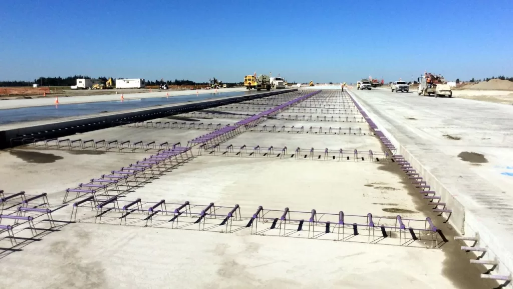
Jointed Reinforced Concrete Pavement (JRCP)
JRCP incorporates steel reinforcement within the concrete slabs and features longer joint spacing, typically ranging from 30 to 40 feet. As a result, the reinforcement effectively helps control cracking between the joints, thereby maintaining the structural integrity of the pavement. Additionally, dowel bars and tie bars are strategically placed at transverse and longitudinal joints, respectively, to ensure efficient load transfer and proper alignment.
Moreover, this design is particularly suitable for areas experiencing heavier traffic loads, as it provides enhanced durability and long-term performance. Consequently, JRCP serves as a reliable cement concrete road solution, offering both strength and stability. Ultimately, its combination of reinforcement and optimized joint spacing makes it an excellent choice for modern road infrastructure.

Contraction Joints
These are intentionally placed joints in the concrete pavement to control where cracks occur. In JRCP, the spacing of transverse joints typically ranges from 25 to 50 feet (7.6 to 15.2 meters). These joints allow the concrete to shrink as it cures, reducing the likelihood of random cracking.
Reinforcing Steel
JRCP incorporates reinforcing steel or steel mesh to hold cracks tightly together. While the longer slab lengths in JRCP make cracking inevitable due to concrete’s natural shrinkage and thermal contraction, the reinforcing steel ensures that cracks remain tight and do not widen significantly. This helps maintain the pavement’s structural integrity and load-bearing capacity.
Dowel Bars
Dowel bars are used at transverse joints to facilitate load transfer between adjacent slabs. These bars allow for vertical movement while ensuring that loads are effectively transferred across the joint, reducing stress concentrations and preventing faulting (unevenness at the joint).
Load Transfer Across Cracks
The reinforcing steel or wire mesh in JRCP not only holds cracks together but also assists in transferring loads across the cracks. This helps distribute traffic loads more evenly, reducing the risk of localized damage and extending the pavement’s service life.
Advantages of JRCP
- Crack Control: The combination of joints and reinforcement ensures that cracks are controlled and do not compromise the pavement’s performance.
- Durability: The use of reinforcing steel and dowel bars enhances the pavement’s ability to withstand heavy traffic and environmental stresses.
- Load Distribution: Effective load transfer mechanisms reduce the risk of joint faulting and slab cracking.
Disadvantages of JRCP
- Cost: The inclusion of reinforcing steel and dowel bars increases material costs. Construction costs also rise compared to simpler pavement types like Jointed Plain Concrete Pavement (JPCP).
- Maintenance: JRCP is designed to control cracking. However, the presence of reinforcing steel can complicate repairs if the pavement eventually fails.
In summary, JRCP is a robust pavement design. It uses a combination of contraction joints, reinforcing steel, and dowel bars. These elements manage cracking and ensure effective load transfer. This makes it suitable for roads and highways subject to heavy traffic and environmental stresses.
Continuously Reinforced Concrete Pavement (CRCP)
CRCP is the most advanced type in concrete road construction, as it features continuous steel reinforcements throughout the slab. Consequently, this design eliminates transverse joints, making it particularly ideal for high-traffic areas such as highways and airports. Additionally, CRCP uses reinforcement to hold tightly spaced cracks together, thereby creating a smooth and highly durable surface.
Moreover, CRCP concrete road construction is especially suitable for high-traffic areas because it offers superior performance while requiring minimal maintenance. As a result, this construction method ensures long-lasting pavement that can withstand heavy loads and harsh environmental conditions. Ultimately, its combination of strength, durability, and reduced upkeep makes CRCP a preferred choice for modern infrastructure projects.
CRCP offers exceptional durability and requires minimal maintenance for cement concrete roads. The steel mesh prevents cracks and distributes traffic loads evenly across concrete road layers, ensuring a smooth and long-lasting surface. CRCP uses high-strength road construction concrete to withstand heavy loads and extreme weather conditions. Its seamless design reduces maintenance costs and enhances the performance of concrete road construction, making it a top choice for critical infrastructure projects.
Choosing the appropriate type of concrete pavement depends on factors such as traffic load, environmental conditions, and budget considerations. Each type offers distinct advantages in concrete road construction, contributing to the development of durable and efficient transportation infrastructure.
Advantages of Concrete Roads
Concrete roads offer several advantages over other paving materials:
- Durability and Longevity:
Concrete roads are known for their exceptional durability, as they can withstand heavy traffic loads and adverse weather conditions. As a result, they offer a longer service life compared to other road construction materials. Furthermore, this durability ensures lower maintenance costs over time, making concrete roads a cost-effective option for long-term use. - Low Maintenance Requirements: Once constructed, concrete roads demand relatively low maintenance. Their resistance to wear and tear reduces the frequency of repairs, making them a cost-effective choice in the long run.
- Resistance to Weathering and Heavy Loads: Concrete’s high stiffness and negligible wear and tear make it resistant to environmental factors such as water, extreme temperatures, and UV radiation. This resistance helps maintain the structural integrity of the road over time.
- Improved Fuel Efficiency for Vehicles: Concrete roads are more economical to drive on in terms of fuel consumption, as they reflect light better and provide a smoother surface, contributing to better fuel efficiency for vehicles.
Methods of construction of cement concrete roads
Cement concrete roads are constructed through three primary methods, each designed to meet specific project requirements and conditions.
Alternate Bay Method
In this approach, the contractor divides the road into alternate bays, typically ranging from 6 to 8 meters in length. They construct the road in these alternate sections, ensuring each bay cures properly before constructing the adjacent bays. This method allows for effective curing and prevents premature construction, ultimately enhancing the quality of the road. This method helps in managing shrinkage and thermal stresses effectively, reducing the likelihood of cracks. However, it requires more time to complete since only alternate sections are worked on at a time. Additionally, during adverse weather conditions, water may collect in the unconstructed bays, potentially causing delays.
Continuous Bay Method
Also known as the strip method, this technique involves constructing the entire width of the road continuously without any breaks from one end to the other. Transverse joints, known as dummy joints, are provided at regular intervals (typically around 5 meters) to control cracking by creating planes of weakness. This method ensures a uniform surface and is suitable for projects requiring rapid completion. However, it necessitates careful planning to manage the setting time of concrete and to ensure proper curing across the entire stretch.
Expansion Joint and Strip Method
In this method, the engineers incorporate expansion joints at regular intervals to accommodate temperature-induced expansions and contractions. This prevents uncontrolled cracking and ensures the road remains structurally stable over time. By strategically placing these joints, they allow for controlled movement while maintaining the integrity of the pavement.These joints allow the concrete slabs to expand and contract with temperature variations without causing damage to the pavement. This technique is essential for long stretches of pavement, especially in regions experiencing significant temperature fluctuations. Proper placement and construction of these joints are crucial to maintain the structural integrity and longevity of the road.
Each method offers distinct advantages, and the choice depends on factors such as project scale, environmental conditions, and desired durability.
Steps involved in road construction
Constructing a cement concrete road involves several critical steps to ensure durability and longevity. Each phase plays a vital role in achieving a high-quality pavement.
Preparation of Subgrade
The subgrade is the native soil layer that serves as the foundation for the road. Preparation involves clearing the site of vegetation, debris, and any unsuitable materials. The soil is then leveled and compacted to achieve the desired density and strength. Proper subgrade preparation ensures uniform support for the pavement, preventing future settlement and distress. In cases where the subgrade soil is weak, stabilization techniques or additional layers may be applied to enhance its load-bearing capacity.
Placement of Formwork
Formwork refers to temporary molds used to shape and support the concrete until it hardens. In road construction, workers set sturdy forms along the edges of the proposed pavement to define its boundaries and maintain the desired thickness. They must accurately align and securely anchor these forms to withstand the pressure of the poured concrete. Consequently, proper formwork ensures consistent pavement dimensions and well-formed edges, contributing to the overall structural integrity.
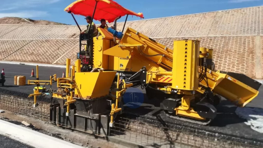
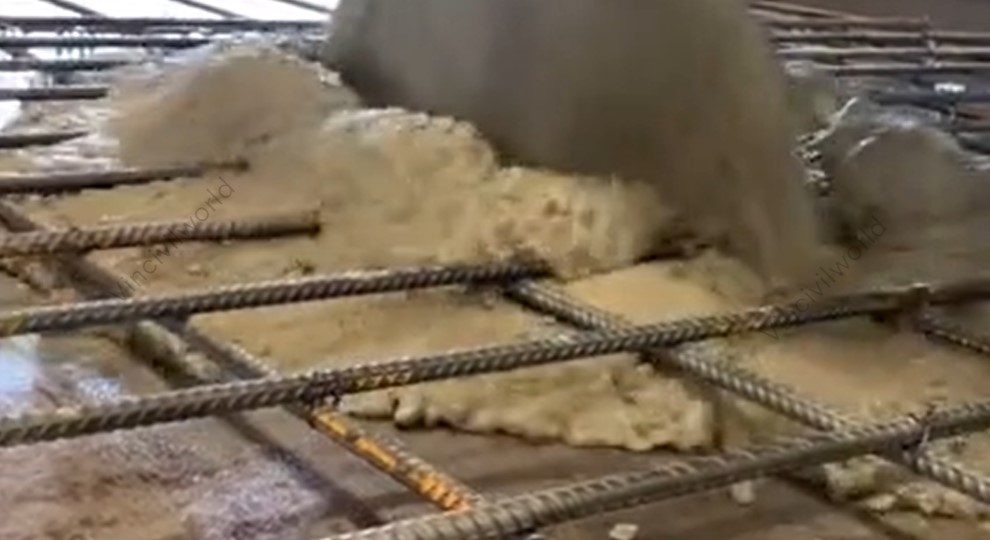
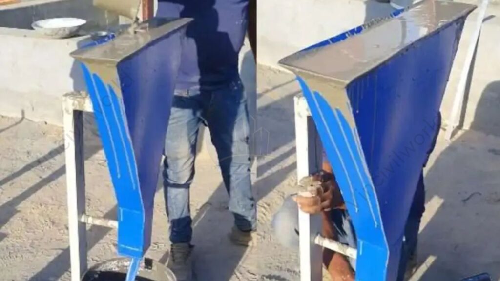
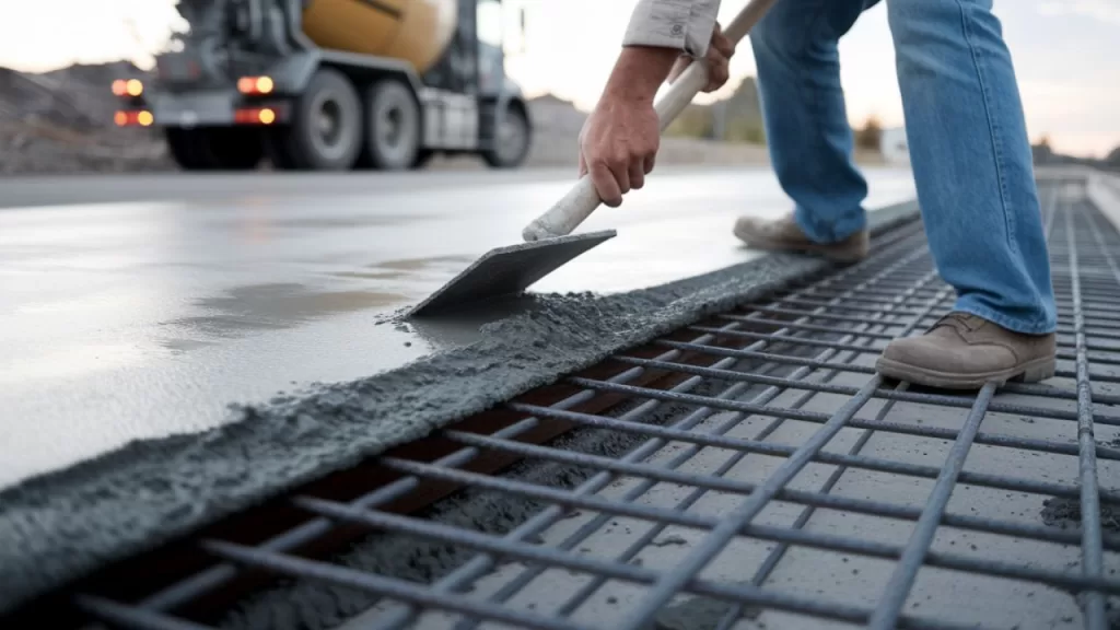
Mixing and Pouring of Concrete
Workers prepare concrete by mixing cement, aggregates (such as sand and gravel), water, and any necessary admixtures in specified proportions. They perform this mixing either on-site or at a batching plant. Afterward, they transport the mixed concrete to the site and pour it into the prepared formwork. It’s essential to pour the concrete promptly to prevent premature setting. Consistent mixing and timely pouring ensure a uniform composition, which is crucial for the pavement’s strength and durability
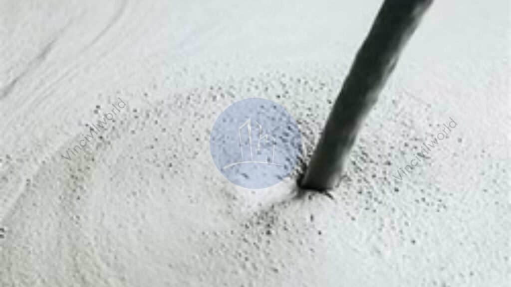
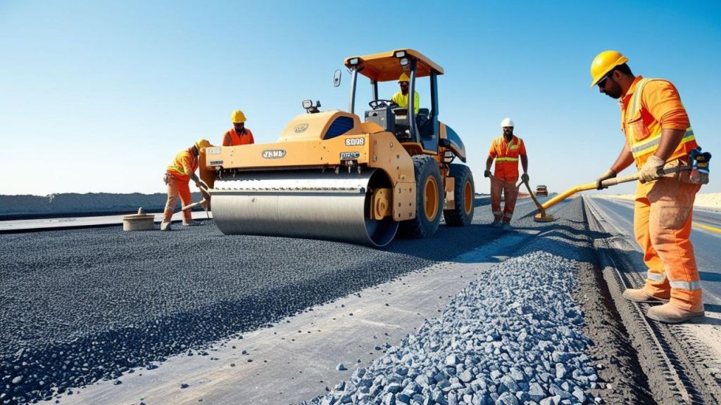
Compaction and Finishing
After pouring the concrete, workers must compact it to eliminate air voids and achieve the desired density. They typically use vibrators to ensure the concrete settles properly around any reinforcement and into all corners of the formwork. Following compaction, they level and smooth the surface using tools like screeds and trowels. Proper compaction is crucial, as it enhances the strength and durability of the concrete by removing entrapped air and consolidating the mixture. Finishing may also involve creating surface textures to enhance skid resistance. Proper compaction and finishing are vital for the pavement’s structural performance and surface quality.
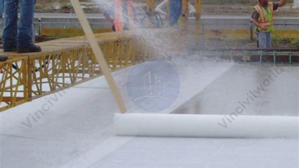
Curing Process
Curing involves maintaining adequate moisture and temperature conditions to allow the concrete to achieve its intended strength. This process typically lasts for several days and can be accomplished by methods such as covering the surface with wet burlap, applying curing compounds, or using plastic sheeting. Proper curing prevents the concrete from drying too quickly, which can lead to surface cracking and reduced durability. It’s a critical step to ensure the longevity of the pavement.
Joint Cutting and Sealing
Once the concrete has gained sufficient strength, joints are cut into the pavement to control cracking caused by temperature changes and shrinkage. These joints are typically spaced at regular intervals and can be of various types, including contraction, expansion, and construction joints. After cutting, workers thoroughly clean the joints and carefully apply appropriate sealants. This process effectively prevents the infiltration of water and debris, which could otherwise compromise the pavement’s integrity. Moreover, proper joint cutting and sealing play a crucial role in maintaining the road’s overall performance while significantly extending its service life.
Furthermore, each of these steps is essential for constructing a durable and long-lasting cement concrete road. By paying close attention to every phase, from preparation to finishing, workers ensure that the pavement can withstand heavy traffic loads and varying environmental conditions throughout its intended lifespan. Consequently, a well-executed construction process leads to stronger, more resilient roads that require minimal maintenance over time.
Disadvantages of concrete road construction
Concrete road construction offers durability and strength, but it also presents several challenges:
- High Initial Construction Cost: Building concrete roads requires a significant upfront investment. This is due to the cost of materials and skilled labor.
- Extended Construction Time: The curing process of concrete is time-consuming, leading to longer project durations compared to asphalt roads.
- Difficulty in Maintenance: Repairing damaged concrete roads can be challenging. Often, it requires replacing entire slabs rather than simple patching.
- Lower Comfort and Noise Issues: Concrete’s rigidity can result in a noisier and less comfortable driving experience due to its poor shock absorption and higher noise levels.
- Susceptibility to Cracking: Concrete roads are prone to cracking under heavy loads and temperature variations, which can compromise their structural integrity over time.
These factors should be carefully considered when planning and implementing concrete road projects.
Maintenance Practices for Concrete Roads
Concrete road resurfacing and rehabilitation involve various methods to restore pavement functionality and extend service life:
- Joint and Crack Sealing: Involves cleaning and filling existing joints and cracks with sealant to prevent water infiltration and debris accumulation, thereby reducing further deterioration.
- Slab Stabilization: Addresses voids beneath concrete slabs by injecting grout to restore support and prevent faulting or cracking.
- Diamond Grinding: Removes surface irregularities and restores smoothness by grinding the concrete surface, improving ride quality and skid resistance.
- Partial-Depth Repair: Targets surface-level distress by removing and replacing the top portion of the slab, addressing issues like spalling.
- Full-Depth Repair: Involves removing and replacing entire concrete slabs or sections to address severe damage extending through the slab.
- Load Transfer Restoration: Enhances load distribution across joints by installing dowel bars, improving structural capacity and extending pavement life.
- Concrete Overlays: Applies a new concrete layer over existing pavement to increase structural capacity and address surface deficiencies.
Selecting the appropriate method depends on the pavement’s condition, distress types, and project objectives.
Innovations and Future Trends in Concrete Road Construction
Smart concrete and self-healing materials represent significant advancements in construction technology. Key points include:
- Self-Sensing Capabilities: Smart concrete can monitor its own structural health. It does so by embedding sensors or conductive materials. This allows it to detect stress or damage in real-time.
- Self-Healing Mechanisms: Incorporating materials like superabsorbent polymers or specific bacteria enables the concrete to autonomously repair cracks, enhancing durability and reducing maintenance needs.
- Environmental Benefits: Extending the lifespan of structures and reducing the need for repairs contribute to sustainability in construction.
- Enhanced Durability: Self-healing properties allow the concrete to recover from internal damage without external intervention, limiting reinforcement corrosion and concrete deterioration.
- Innovative Additives: The use of carbon nanotubes, mineral admixtures, and shape memory alloys improves the unique properties of smart concrete.
These innovations aim to create more resilient, sustainable, and low-maintenance infrastructure.
Key Takeaways
Concrete road construction offers unparalleled durability and longevity, often lasting 20-40 years, which is two to four times longer than asphalt roads.
This longevity translates to lower maintenance costs over time, making it a cost-effective choice for modern infrastructure. The typical layered design—comprising subgrade, sub-base, base, and concrete slab—ensures exceptional strength and stability. Although the initial investment is higher compared to asphalt, the long-term savings and environmental benefits make concrete road construction a wise investment. Innovations such as self-healing concrete, which can repair its own cracks, further enhance performance and extend service life.
Proper curing, jointing, and high-quality materials are critical to success. Despite challenges like cracking and temperature sensitivity, concrete road construction remains a reliable solution for highways, urban roads, and industrial zones, ensuring safe and sustainable travel for decades.
Conclusion
Concrete road construction is a cornerstone of durable and sustainable infrastructure. Its ability to withstand heavy traffic, harsh weather, and long-term wear makes it ideal for modern roadways. By optimizing concrete road layers and using high-quality materials, engineers can create pavements that last 30–40 years with minimal maintenance. While challenges like cost and cracking exist, advancements in technology and construction techniques continue to improve its efficiency and performance. Embracing concrete road construction ensures safer, smoother, and more eco-friendly roads, paving the way for resilient and future-ready transportation networks.