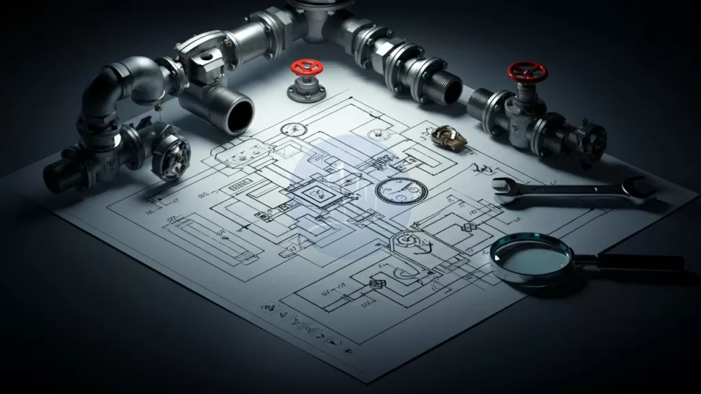
Piping isometric drawings are essential tools in the engineering and construction of pipeline systems. They provide a three-dimensional representation of pipelines in a two-dimensional format, helping engineers visualize complex layouts. Unlike other drawing styles, piping isometric drawings depict the height, width, and depth of the pipeline. This depiction allows for precise planning and communication among project teams. These drawings are critical for pipeline fabrication and ensure that installations align with design specifications.
In this article, we will explore piping isometric drawing symbols. We will also cover isometric pipe drawing symbols and how to read isometric piping drawings. Understanding these symbols and techniques is crucial for accurate and effective pipeline design and construction.
- Key Components of Piping Isometric Drawings
- Importance of Isometric View in Piping
- Piping Isometric Drawing Symbols
- How to Read Piping Isometric Drawings
- Representation of pipe fittings in piping isometric drawings
- Applications of Isometric Drawings in Piping Systems
- Annotations and Labels in Piping Layout Drawings
- Color Code in Piping Systems
- Applications of Isometric Drawings in Piping Systems
- Steps to Create Isometric Drawings for Piping
- Common Challenges in Isometric Piping Drawings
- Comparison of Isometric and Orthographic Drawings
- Piping Isometric Drawing Standards and Guidelines
- Three Main Rules in Isometric Drawing
- Conclusion
Key Components of Piping Isometric Drawings
Piping isometric drawings are crucial in pipeline design, providing 3D representations in a 2D format. They simplify complex layouts, enhance visualization, and ensure accurate fabrication with standardized symbols and clear details.
Key features of isometric drawings for piping include:
- A 30-degree angle projection for all axes to show depth.
- Use of Standardized Symbols: Incorporates symbols for pipes, valves, elbows, and fittings, ensuring consistency and ease of understanding.
- Precise Dimensions: Includes detailed measurements and angles, aiding accurate fabrication and assembly.
- Annotations and Notes: Offers material specifications, pipe sizes, welding instructions, and operational details.
- Flow Direction Indicators: Utilizes arrows and markings to show the flow direction of fluids within the pipeline.
- Simplified Layout Interpretation: Easier to read compared to other technical drawings, helping teams visualize complex configurations.
- Fabrication-Friendly Design: Acts as a guide for manufacturers, reducing errors and material wastage.
- Compliance: Ensures adherence to design and construction standards, supporting effective project execution.
- Inclusion of key elements such as piping symbols for isometric drawings, directional arrows, and dimension lines.
These features make isometric drawings of pipelines a preferred choice for complex projects.
Importance of Isometric View in Piping
The isometric view in piping is a visual representation technique. It shows all three dimensions length, width, and height—at equal scales. This unique perspective simplifies complex pipeline layouts, making it easier for engineers to interpret designs accurately. Isometric views provide a clear and comprehensive depiction of the pipeline geometry. This clarity allows engineers to identify potential design challenges or conflicts before construction begins. This visualization method enhances communication among project teams. It ensures that intricate systems are easier to comprehend. This approach ultimately saves time and reduces errors in fabrication and installation processes. The isometric view in piping plays a vital role in streamlining project execution and improving overall design accuracy.
More related posts
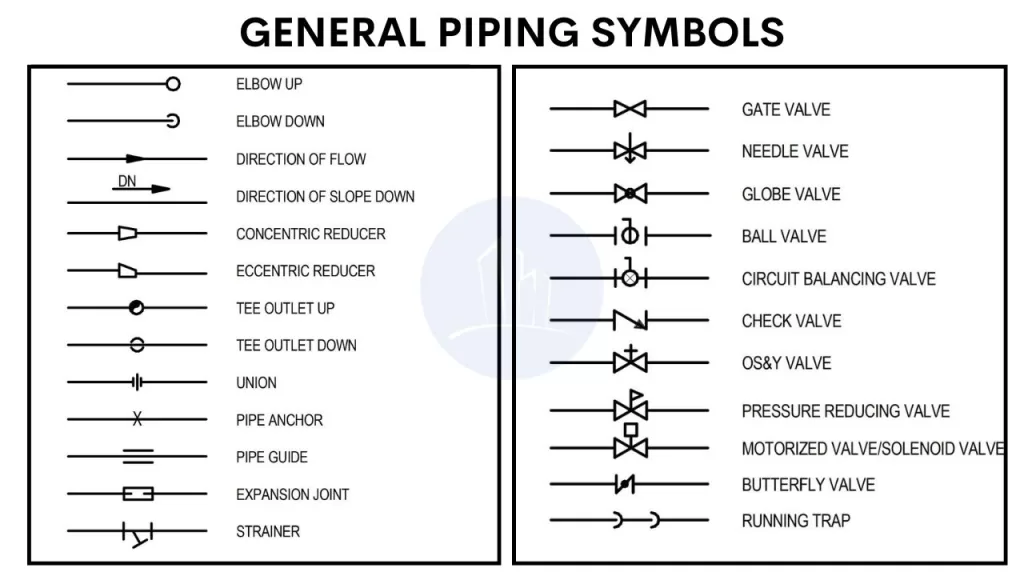
Piping Isometric Drawing Symbols
Piping isometric drawing symbols act as a universal language for engineers and fabricators.
Piping isometric drawings represent three-dimensional pipeline systems on a 2D plane. They offer a clear understanding of complex pipe routing across multiple planes. These drawings use single-line representations of pipe centerlines to measure dimensions. They incorporate symbols for components like valves, flanges, reducers, and welds. Common symbols include:
- Valves: Represented by geometric shapes such as circles or rectangles with annotations.
- Flanges: Depicted as two parallel lines intersecting the pipe.
- Reducers: Indicated by a tapered line connecting different pipe diameters.
- Elbows: Shown with angular bends.
How to Read Piping Isometric Drawings
Understanding isometric pipe fittings drawings is crucial when handling complex pipeline systems. These drawings offer a three-dimensional visualization of piping layouts on a two-dimensional surface. They aid engineers, designers, and operators in effective planning and execution. A standard 30-degree angle is applied to the axes, which ensures equal foreshortening of length, width, and height.
This creates a proportional and clear perspective. This approach provides precise information about pipe routes, dimensions, and connection details. It makes it easier to analyze and implement designs. Additionally, it minimizes errors during construction or maintenance. Mastery of isometric pipe fittings drawings enhances efficiency and communication among all stakeholders in pipeline projects.
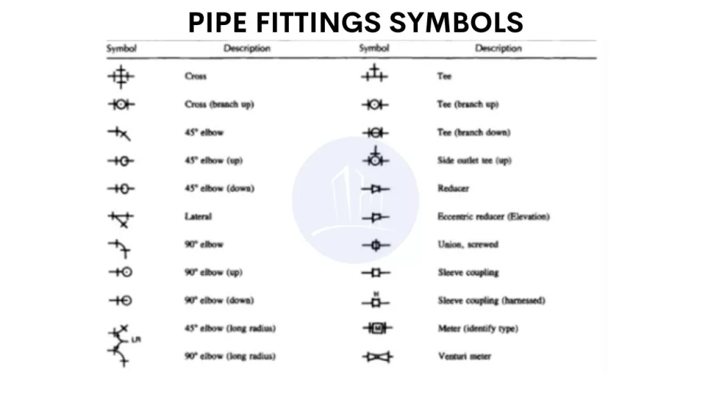
Representation of pipe fittings drawings
Piping isometric drawings use standardized symbols to represent different pipe fittings and components. These symbols convey critical information about the type, size, and orientation of pipes, valves, and other equipment. Recognizing these symbols is essential for accurately interpreting the layout and functionality of the piping system depicted in the drawing.
Representation of pipe fittings and pipe materials
Piping isometric drawings specify the material of the pipes, such as carbon steel, stainless steel, copper, or PVC. This information is crucial for understanding the system’s properties and requirements.
In piping isometric drawings, pipes are represented as single lines to simplify the layout. These lines include key information such as pipe size, material, and specification. Arrows indicate flow direction, while symbols represent fittings, valves, and connections. The drawings maintain a 30-degree angle for clarity and accurate visualization.
Representation of pipe fittings in piping isometric drawings
Each fitting is represented by a unique symbol on the isometric drawing. This allows you to quickly identify the components. You can also see their orientation within the system.
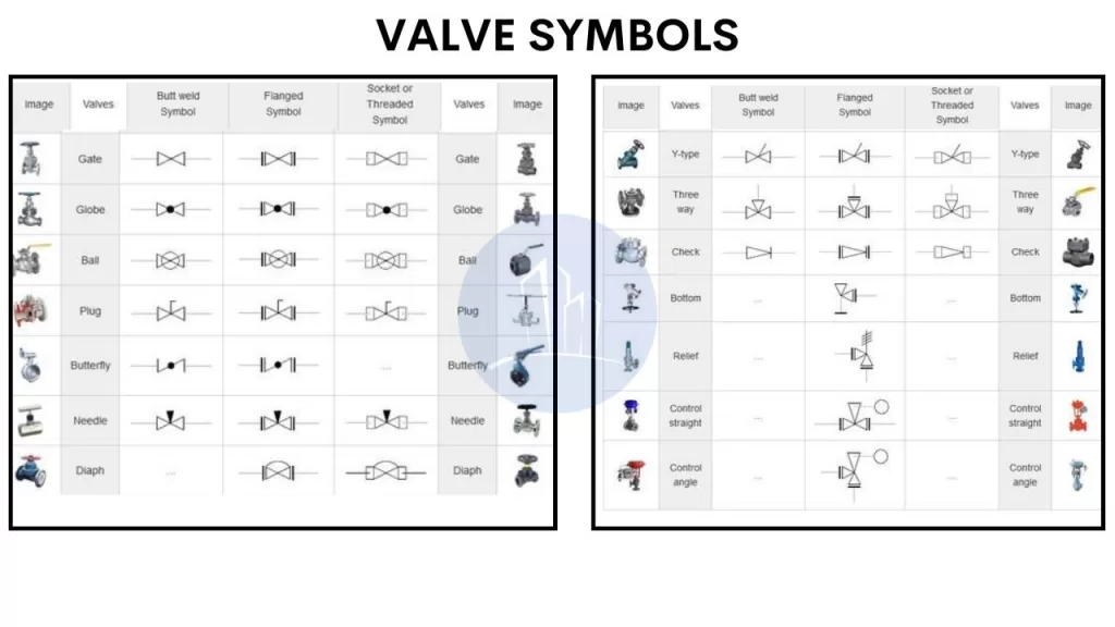
Valve Symbols
Piping isometric drawings use standardized symbols to represent different types of valves, such as ball, gate, and globe valves. These symbols are typically color-coded to distinguish the valve type.
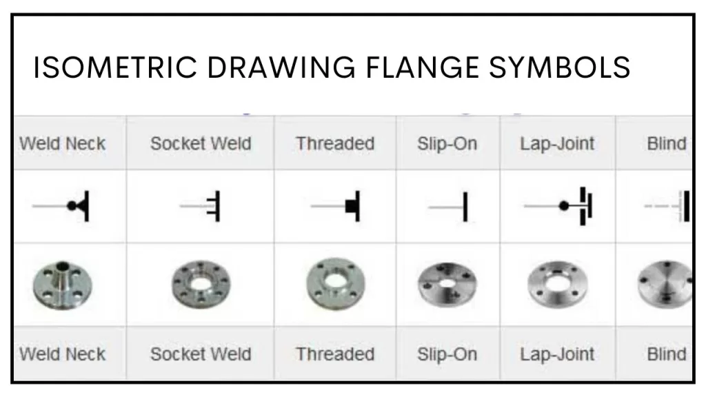
Flanges symbols
Flange symbols in piping isometric drawings represent the connection points between pipes or pipe and equipment. These symbols vary based on flange type.
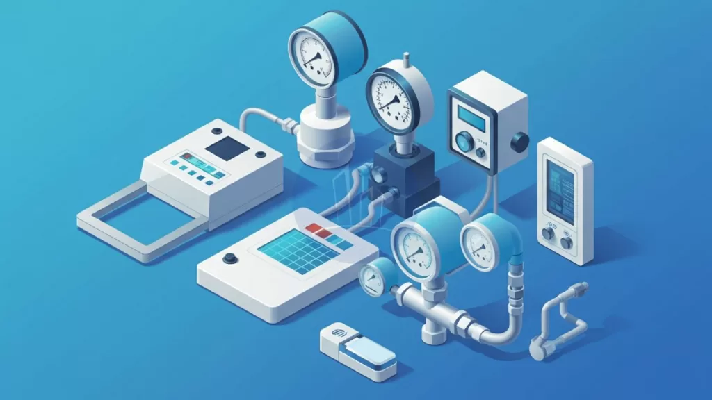
Instrument Symbols
Instruments like pressure gauges, thermometers, and flow meters are also depicted using standardized symbols in isometric drawings. These help identify the location and type of instrumentation along the piping system.
Applications of Isometric Drawings in Piping Systems
Piping layout drawings provide critical information essential for designing and constructing pipeline systems. Here’s what can be obtained from them:
- Pipe Routing: Exact pathways of pipes, including elevations and orientations.
- Equipment Locations: Placement of machinery and fixtures in relation to the piping system.
- Material Specifications: Details about pipe materials, insulation, and coatings.
- Dimensions: Measurements of pipe lengths, offsets, and distances between components.
- Fittings and Connections: Types of joints, flanges, and fittings required.
- Support Systems: Locations and types of pipe supports, hangers, and anchors.
- Flow Direction: Indicated by arrows to ensure proper operation.
- Valves and Instruments: Placement and specifications of valves, gauges, and control devices.
- Safety Features: Emergency shut-off systems and pressure-relief valves.
- Compliance Data: Adherence to standards, codes, and regulations.
This ensures accuracy and efficiency in pipeline installation and maintenance.
Annotations and Labels in Piping Layout Drawings
- Pipe Size and Material: Specifies the diameter and material (e.g., steel, PVC) for each pipe, ensuring compatibility.
- Flow Direction: Uses arrows to indicate the direction of fluid or gas flow within the system.
- Equipment Tags: Labels machinery and equipment with unique identifiers for easy referencing.
- Elevation Indicators: Highlights the height or depth of pipes, critical for alignment.
- Connection Details: Annotates welds, flanges, or threaded connections for assembly.
- Valve Types and Numbers: Identifies valve locations, types (e.g., gate, globe), and tag numbers for functionality.
- Support Annotations: Labels pipe supports, hangers, or brackets with their specifications.
- Insulation and Coating: Notes areas requiring thermal insulation or corrosion-resistant coatings.
- Instrument Tags: Marks sensors, gauges, and monitoring instruments with unique labels.
- Safety Instructions: Includes warnings, emergency shutoff points, and safety compliance notes.
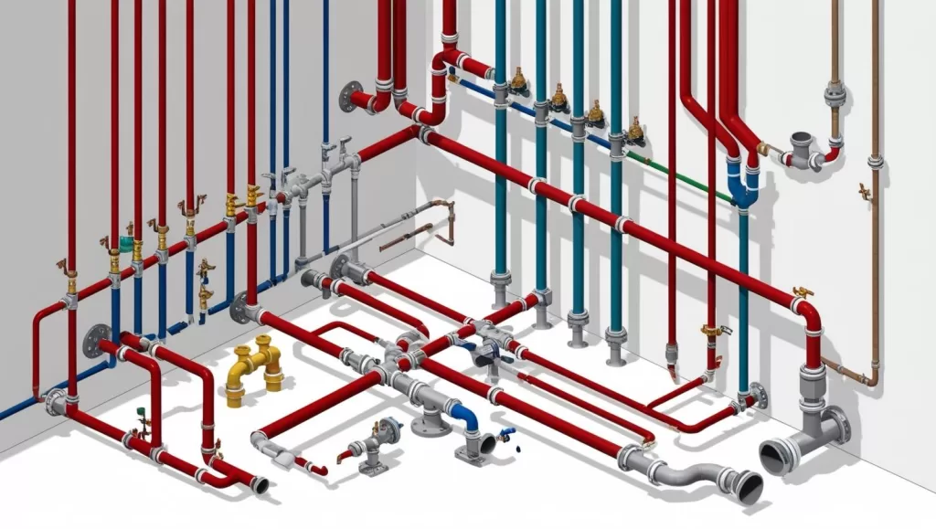
Color Code in Piping Systems
Color coding in piping systems is a standardized method to identify the contents of pipelines for safety and operational efficiency. It aids in quick recognition during maintenance and emergencies.
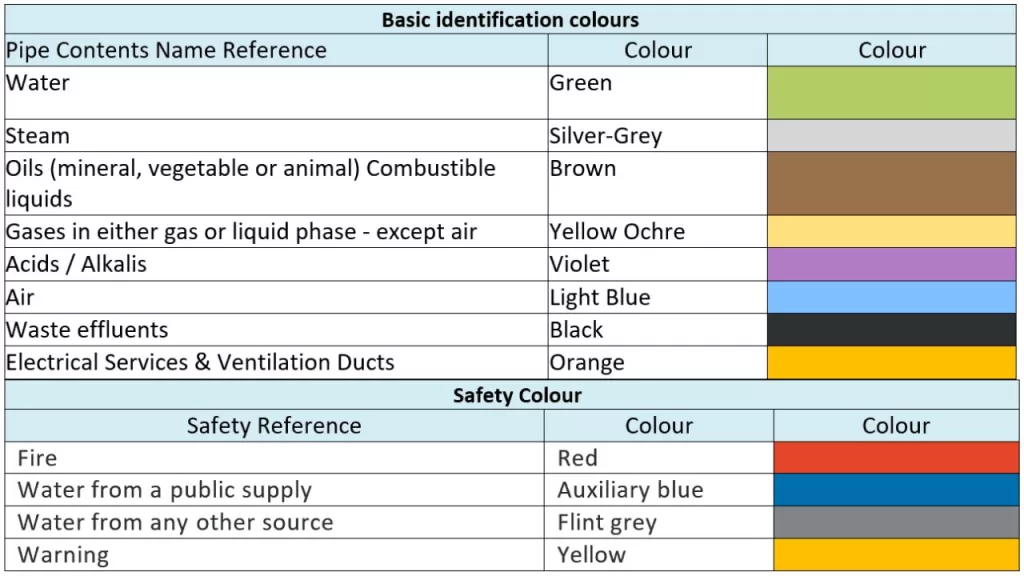
- Fluid Type Identification: Different colors represent various fluids like water, steam, oil, or gases.
- Hazard Awareness: Highlights dangerous contents, such as flammable or toxic substances.
- Directional Arrows: Used alongside color codes to indicate the flow direction.
- Compliance Standards: Adheres to codes like ANSI/ASME A13.1 or ISO standards for global consistency.
- Maintenance Assistance: Simplifies troubleshooting by providing instant recognition of pipeline contents and purpose.
A well-read piping isometric drawing minimizes errors in pipeline fabrication and installation.
Applications of Isometric Drawings in Piping Systems
Isometric drawings are vital for designing, installing, and maintaining piping systems, providing comprehensive details about dimensions, layout, and materials in a three-dimensional perspective.
Applications
- Design Visualization: Offers a clear 3D view of piping layouts, simplifying complex designs.
- Fabrication Guidance: Specifies pipe lengths, angles, and fittings, aiding precise fabrication.
- Installation: Guides field teams on accurate pipe placements and alignment.
- Material Estimation: Lists materials required for efficient planning and procurement.
- Maintenance and Repair: Identifies pipe locations and connections for quick repairs.
- Conflict Resolution: Highlights spatial clashes to prevent on-site issues.
- Compliance: Ensures designs meet safety and engineering standards.
Steps to Create Isometric Drawings for Piping
Creating isometric drawings for piping involves several key steps to ensure precision. Start by preparing the piping layout, including all components like valves, elbows, tees, and pumps. Set up the isometric grid at the required scale, using a 30-degree angle to represent the three dimensions. Define pipe diameters to mark the size of each pipe accurately. Next, plot the piping components, including pipe runs, fittings, and equipment, using the grid. Add details like material types, flow direction, and any additional specifications. Finally, review and validate the drawing for accuracy, ensuring it aligns with the engineering design.
Various software tools can streamline this process. AutoCAD is great for both 2D and 3D piping designs with isoplane settings. Revit, used in BIM-based designs, generates detailed isometric views and integrates with other data. Tools like SolidWorks, SmartPlant 3D, and MicroStation enhance 3D modeling, offering automation and flexibility for efficient, accurate isometric piping designs.
Common Challenges in Isometric Piping Drawings
Challenges in isometric drawings for pipelines include:
- Scaling Issues: Misinterpretation of dimensions is common when scaling the drawing. Accurate scaling is crucial to ensure that components fit as designed in the real-world installation.
- Symbol Miscommunication: Incorrect or inconsistent use of isometric pipe drawing symbols can lead to errors. Adhering to industry standards ensures clarity and prevents confusion during the construction or maintenance stages.
- Complexity in Detailing: Representing multiple components such as valves, joints, and fittings in a three-dimensional system can be overwhelming, requiring careful attention to maintain accuracy and detail.
- Alignment and Layout: Improper alignment of pipes and components can disrupt the flow of the design and cause potential installation issues.
Comparison of Isometric and Orthographic Drawings
The Piping isometric drawings and orthographic drawings serve different purposes:
- Isometric Drawings: Provide a 3D perspective, showing depth, width, and height in a single view, ideal for visualizing complex systems.
- Orthographic Drawings: Focus on individual planes (top, side, front), giving precise measurements for construction but lacking the 3D perspective.
- Complex Layouts: Isometric views in piping offer superior clarity and help in understanding the spatial arrangement of components.
Piping Isometric Drawing Standards and Guidelines
International Standards:
- ISO 128-30:2017 – This standard outlines the general principles for creating isometric drawings. It includes the use of a 30-degree angle for projections. These projections represent three-dimensional objects on a two-dimensional plane. It ensures uniformity across industries and geographical boundaries.
- ASME Y14.5-2009 – The American Society of Mechanical Engineers (ASME) standard provides guidelines on dimensional tolerances, including isometric drawings. It also covers how to represent pipe sizes, materials, and flow directions.
- ANSI/ASME B31.3 – This standard for Process Piping explains how isometric drawings should accurately represent the piping system. It includes component layout and material specifications. Additionally, it standardizes symbols for valves, flanges, and fittings.
- ISO 5457:2012 – This specifies the size of drawings. It includes the standard sheet size used for isometric drawings. This ensures they are universally recognizable and maintain clarity.
Indian Standards:
- IS 696:1972 – The Indian Standard for Engineering Drawing lays the foundation for isometric projections. It also standardizes the use of symbols for different components like valves, elbows, and flanges. It is consistent with international practices in dimensioning and symbol representation.
- IS 10701:1983 – This standard applies to the design and drafting of piping systems. It offers specific guidelines for the representation of isometric drawings. It also includes material codes and component alignment.
- IS 1235:1982 – This standard focuses on the quality of engineering drawings. It establishes conventions for piping isometric drawings, including scale and symbol usage. These conventions ensure clear communication in the installation and maintenance of piping systems
By adhering to these standards, designers and engineers can create isometric drawings that are clear and standardized. These drawings are easily interpretable across regions and industries.
Three Main Rules in Isometric Drawing
In isometric drawing, three main rules ensure accuracy and clarity:
- 30-Degree Angle: The drawing is created using a 30-degree angle to show all three dimensions (length, width, and height) equally foreshortened.
- Equal Scaling: All axes should be scaled equally to maintain proportionality and prevent distortion.
- Straight Lines: Maintain straight lines for pipes and components, ensuring accurate measurements and preventing confusion.
These rules help in creating precise, easy-to-read representations of three-dimensional systems on a two-dimensional plane.
Key Takeaways: Piping Isometric Drawings and Symbols
- Essential for Piping: Isometric drawings provide a 3D representation of complex pipeline systems on a 2D plane, showing height, width, and depth for precise planning and communication.
- Standardized Symbols: These drawings use universally recognized symbols for components like valves, flanges, and fittings, ensuring clarity and consistency in interpretation.
- Simplified Visualization: The isometric view simplifies complex layouts, aiding engineers and project teams in visualizing and understanding intricate pipeline configurations.
- Fabrication and Installation Guidance: Precise dimensions, annotations, and material specifications in isometric drawings guide accurate fabrication and installation processes. This reduces errors and ensures compliance with design requirements.
- Effective Communication: Piping isometric drawings facilitate clear communication among engineers, fabricators, and installers, ensuring accurate execution and minimizing potential conflicts.
- Standards and Guidelines: Adhering to international and national standards ensures the quality, consistency, and universal interpretability of isometric drawings.
Conclusion
Piping isometric drawings play a critical role in the design, installation, and maintenance of piping systems. Their 3D representation ensures clarity, making complex piping layouts easier to understand and execute. By incorporating standardized symbols for fittings, flanges, and instrumentation, these drawings effectively communicate critical design details. Understanding annotations, color codes, and material representations further enhances their utility. Comparing isometric to orthographic views underscores the unique advantages of each in project execution. Adhering to established standards and guidelines enhances the value of isometric drawings. This adherence ensures precision and efficiency in piping projects across industries. Mastery of these drawings empowers engineers and technicians to streamline workflows, minimize errors, and achieve successful project outcomes.