Radiography test is a non-destructive testing (NDT) method. It uses X-rays or gamma rays to examine the internal structure of materials. This technique is essential for detecting hidden flaws without causing damage, ensuring the integrity and safety of components. Radiography test is widely applied in industries such as manufacturing, construction, and aerospace to inspect welding, castings, and structural components. The process involves placing the test object between a radiation source and a detector. An image is captured that reveals internal features. It highlights potential defects. Advancements in digital radiography have enhanced the efficiency and accuracy of these inspections. This process has solidified Radiographic testing as a cornerstone in quality assurance and safety protocols across various sectors.
In this article, we will delve into the principles, techniques, and applications of Radiography test. We’ll explore its significance in non-destructive evaluation, the equipment utilized, and the step-by-step process involved. Additionally, we’ll emphasis on the advantages, limitations, safety considerations, and recent advancements in the field. This comprehensive guide aims to offer a thorough understanding of radiography test and its pivotal role across various industries.
- Principles of Radiography test
- Types of Radiography Tests
- Equipment Used in Radiography Test
- Applications of Radiography test
- Advantages of Radiography test
- Limitations and Safety Considerations of Radiography test
- Recent Advances in Radiography Test
- Conclusion
- Key takeaways
Principles of Radiography test
Radiography test is a non-destructive testing (NDT) method. It utilizes X-rays or gamma rays to examine the internal structure of materials. The fundamental principle involves directing radiation through a test object. The radiation is projected onto a detector, like photographic film or a digital sensor. Variations in material density and thickness affect the absorption of radiation. Denser areas absorb more, resulting in lighter regions on the radiography. Meanwhile, less dense areas are darker. This contrast enables the detection of internal flaws like cracks, voids, or inclusions. Radiography test is widely applied across industries. These include aerospace, construction, and manufacturing. This ensures the integrity and reliability of critical components.

In radiography tests, X-rays and gamma rays interact with materials primarily through three mechanisms:
- Photoelectric Absorption: Low-energy photons are absorbed by tightly bound electrons, ejecting them from atoms. This effect is more pronounced in materials with higher atomic numbers.
- Compton Scattering: Moderate-energy photons collide with loosely bound electrons, resulting in photon deflection and energy loss. This process contributes to image contrast but can also cause image blurring.
- Pair Production: High-energy photons (above 1.022 MeV) can transform into an electron-positron pair near a nucleus. This phenomenon becomes significant at higher photon energies.
These interactions cause attenuation of the radiation beam. The degree of attenuation depends on the material’s thickness, density, and atomic number. By analyzing the transmitted radiation, Radiographic testing reveals internal structures and potential defects within the material.
Types of Radiography Tests
Radiography test (RT) is a non-destructive testing method. It employs X-rays or gamma rays to inspect the internal structure of materials. This ensures the integrity and reliability of components across various industries.
- Film Radiography
- Digital Radiography (DR)
- Computed Radiography (CR)
- Real-Time Radiography (RTR)
- Computed Tomography (CT)
Each of these radiography testing techniques offers unique advantages. The choice among them depends on specific inspection requirements. It also relies on material types and desired image clarity.
Film Radiography test
Film radiography is a traditional non-destructive testing (NDT) method. It effectively utilizes X-rays or gamma rays. These rays inspect the internal integrity of materials and components. In this process, a Radiographic film is placed behind the test object, and radiation is directed through the material. As a result, variations in material density and thickness affect the radiation’s absorption, creating a latent image on the film. Once the chemical processing is complete, this film reveals an image highlighting internal features and potential defects like cracks, voids, or inclusions. Due to its precision, film radiography is renowned for its high-resolution imaging capabilities, making it a reliable choice for detecting even the smallest irregularities. This makes it a preferred choice in industries like aerospace, construction, and manufacturing. Despite advancements in digital radiography, film radiography remains valued for its ability to produce detailed images essential for critical inspections.
Digital Radiography test
Digital Radiography (DR) is an advanced non-destructive testing (NDT) method. It employs digital detectors to capture X-ray or gamma-ray images of a material’s internal structure. Unlike traditional film radiography, DR offers immediate image acquisition and processing, enhancing inspection efficiency and reducing exposure times. This technique provides high-resolution images, facilitating the detection of defects like cracks, voids, and inclusions. Digital Radiography systems also enable easy storage, retrieval, and sharing of digital images, improving workflow and collaboration among inspection teams. Additionally, the Digital Radiography test reduces the need for hazardous chemicals used in film processing. This ultimately promotes a safer and more environmentally friendly work environment. Moreover, its versatility and rapid results have made Digital Radiography testing a preferred choice in various industries, including aerospace, automotive, and oil and gas. In these fields, ensuring the integrity and reliability of critical components is absolutely essential.
Computed Radiography
Computed Radiography (CR) is a modern digital imaging technology that effectively replaces traditional film-based radiography by utilizing photostimulable phosphor (PSP) plates. These advanced plates capture X-ray images efficiently. In this process, the PSP plate is first exposed to X-rays, then stores the image as a latent energy pattern, ensuring accurate and detailed imaging. Subsequently, a laser scanner reads the plate. It releases the stored energy as light. This light is then converted into a digital image for analysis. Computed Radiography offers several advantages over conventional film radiography. These advantages include reduced exposure to radiation and elimination of chemical processing. CR also provides the ability to enhance and digitally archive images. This technology is widely used in medical diagnostics and industrial non-destructive testing, providing a cost-effective and efficient solution for capturing high-quality radiographic images.
Real-Time Radiography test (RTR)
Real-Time Radiography test (RTR) is a non-destructive testing (NDT) technique that enables immediate visualization of an object’s internal structure. X-rays or gamma rays are directed through the test object. They then reach a real-time detector, like a fluorescent screen or digital panel. RTR produces live images and allows for the dynamic observation of components. This immediacy facilitates the detection of defects like cracks, voids, or inclusions during ongoing operations. Real-Time Radiography test (RTR) is widely employed across industries including automotive, aerospace, and electronics. Real-time feedback is crucial in these fields to guarantee part integrity and safety.
Computed Tomography (CT)
Computed Tomography (CT) is an advanced imaging technique that effectively utilizes X-rays to generate detailed three-dimensional representations of an object’s internal and external structures. Unlike traditional methods, the Computed Tomography test captures multiple two-dimensional Radiographic images from various angles. Subsequently, this process reconstructs a comprehensive 3D model, which allows for a thorough examination without causing any damage to the specimen.
Due to its precision and reliability, this non-destructive testing (NDT) method is invaluable across various industries. It is used in aerospace, automotive, and manufacturing and enables precise detection of internal defects. This also allows measurement of complex geometries and verification of material integrity.
Visualizing internal features in high resolution enhances quality control processes. This capability also aids the development of safer and more reliable products. As technology advances, CT continues to evolve. It offers faster scanning times. It also provides improved image clarity. This further solidifies its role as a critical tool in modern NDT practices.
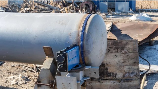
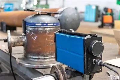
Equipment Used in Radiography Test
Radiographic testing (RT) employs various specialized equipment to inspect the internal structure of materials non-destructively. Essential equipment includes X-ray and gamma-ray sources, detectors, and imaging systems.
Key Equipment Used in Radiographic Testing
- Radiation Sources:
- X-ray Machines: Generate X-rays using X-ray tubes, commonly employed in medical and industrial applications.
- Gamma-ray Sources: Utilize radioactive isotopes like Iridium-192 or Cobalt-60 for material penetration, especially in industrial settings.
- Detectors:
- Film Radiography: Traditional method using photographic film to capture images after exposure to radiation.
- Digital Detectors: Include Computed Radiography (CR) systems with phosphor imaging plates and Digital Radiography (DR) systems with flat-panel detectors for immediate digital imaging.
- Image Processing Systems:
- Computed Tomography (CT) Scanners: Acquire multiple radiographic images from different angles to create detailed cross-sectional views.
- Ancillary Equipment:
- Radiation Shielding: Protective barriers and enclosures to safeguard operators from exposure.
- Film Processors: Develop exposed films in traditional radiography.
- Viewing Stations: Lightboxes or digital monitors for analyzing radiographic images.
The selection of equipment depends on the specific application, material type, and required inspection standards.
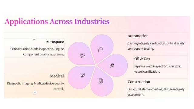
Applications of Radiography test
Radiography Testing (RT) is a crucial non-destructive testing (NDT) method widely used across various industries. Specifically, its main purpose is to assess the internal integrity of materials and components. By utilizing X-rays or gamma rays, RT provides detailed images that effectively reveal internal defects. As a result, this method ensures the safety and reliability of critical structures.
Radiography test for welding
Radiography Test is extensively used to evaluate weld quality in pipelines, pressure vessels, and structural components. It detects defects such as cracks, porosity, and incomplete fusion. Radiography test for welding confirms the weld quality.
Casting Inspection
RT is employed to detect internal defects in metal castings. These defects include shrinkage cavities, gas porosity, and inclusions. This process ensures the structural integrity of cast components.
Aerospace Industry
It ensures the integrity of aircraft components, such as turbine blades and structural elements. It does this by identifying internal flaws that compromise safety.
Automotive Sector
Inspects welds, castings, and assemblies to detect defects affecting vehicle performance and safety.
Petrochemical Industry
Examines pipelines, storage tanks, and pressure vessels for corrosion, cracks, and other defects, preventing potential failures.
Manufacturing
Assesses castings, forgings, and other fabricated components to ensure they meet quality standards by detecting internal discontinuities.
Power Generation
Evaluates critical components in nuclear and conventional power plants. This includes reactor vessels and steam generators. These evaluations ensure structural integrity.
Construction
Checks concrete structures and welds in buildings and bridges for internal defects, ensuring structural safety and compliance with regulations.
Radiographic Testing provides a non-invasive means to detect internal flaws. It plays an essential role in maintaining the quality and safety of products. This ensures infrastructure safety across these sectors.
Advantages of Radiography test
Radiographic Testing (RT) is a non-destructive evaluation method. It uses X-rays or gamma rays. These rays inspect the internal structure of materials and components. This technique offers several notable advantages
High accuracy
RT provides precise detection of internal defects. These include cracks, voids, and inclusions. This precision ensures the integrity of critical components. The radiation source size significantly affects Radiographic testing accuracy. A larger source provides more uniform exposure, creating clearer and more accurate images.
Versatility
RT inspects a wide range of materials, including metals, plastics, and composites. Various industries, such as aerospace, manufacturing, and construction, utilize it.
Minimal Material Limitations
RT can be applied to most types of materials. This makes it a versatile choice for inspecting diverse components.
Volumetric Examination
Considered a universal approach to volumetric inspection, RT examines the internal integrity of objects, providing a comprehensive assessment of their condition.
Permanent Inspection Records
RT produces lasting records of inspections, which can be reviewed and referenced for future evaluations, aiding in quality control and compliance documentation.
Sensitivity to Thickness and Density Variations
RT can detect small changes in thickness and density, down to about 1%, along the path of the X-ray beam, allowing for precise identification of defects.
By providing detailed insights into the internal condition of materials without causing damage, Radiographic Testing plays a crucial role in ensuring the safety, reliability, and quality of products and structures across multiple sectors.
Limitations and Safety Considerations of Radiography test
Radiographic Testing (RT) is a valuable non-destructive testing method, but it has several limitations and safety considerations:
Safety Concerns
The use of ionizing radiation poses potential health hazards to personnel. Strict safety measures, including shielding and monitoring, are essential to minimize risks.
High Operational Costs
RT is relatively expensive. This is due to the cost of equipment and materials. It also requires highly trained operators.
Accessibility Requirements
Both sides of the object must be accessible for effective inspection, which can be challenging for certain components.
Complex Geometry Challenges
Specimens with complex shapes may be difficult to inspect accurately using RT.
Detection Limitations
Small, isolated defects less than 2% of the total thickness may not be detected, and defects not aligned with the radiation beam can be challenging to identify.
Health Risks
Exposure to ionizing radiation can lead to severe health issues, including radiation burns and increased cancer risk.
Environmental Impact
Improper handling and disposal of radioactive materials can adversely affect the environment.
Regulatory Compliance
Strict adherence to radiation safety regulations and guidelines is necessary to protect workers and the public.
Addressing these limitations and safety considerations is crucial for the effective and safe application of Radiographic Testing.
Recent Advances in Radiography Test
Radiographic Testing (RT) has experienced significant advancements, enhancing its accuracy, efficiency, and applicability across various industries. Key developments include:
1. Artificial Intelligence (AI) Integration: AI-powered imaging has revolutionized defect detection and analysis in RT. Advanced algorithms, like 3D Generative Adversarial Networks (GANs), synthesize volumetric computed tomography (CT) data. They help multi-angle defect training. This enables real-time augmentation and improves accuracy.
2. Digital Radiography (DR): The transition from traditional film-based systems to DR has led to faster image acquisition. It has also enhanced image quality and reduced radiation exposure. High-resolution flat-panel detectors and direct conversion sensors further improve diagnostic precision.
3. In-Line Computed Tomography (CT): Integrating CT systems directly into production lines allows for real-time inspection and quality control. AI-driven reductions in scan duration make it easier to detect minute defects. These include 30 µm voids in additive-manufactured parts or cracks in turbine blades.
4. Flexible X-Ray Detectors: Innovations like bendable materials capable of wrapping around complex structures have emerged. These flexible detectors enhance inspections in confined or awkward spaces. They are particularly useful in industries like aeronautics. They offer a versatile option to rigid, flat scanners.
5. Enhanced Software Platforms: Modern software developments provide intuitive touch interfaces. For example, the Rhythm RT platform simplifies operation and increases efficiency. These platforms require minimal operator training and maximize the capabilities of portable Radiographic imaging systems.
6. High-Brightness Photon Sources: High-brightness MeV-photon sources are developed based on laser-wake-field accelerators. This development has opened new possibilities for high-resolution radiography of dense, thick objects. Spatial resolutions better than 2.5 line pairs per millimeter at energies in the MeV range have been demonstrated.
These advancements collectively contribute to more precise, efficient, and versatile radiographic testing, ensuring higher quality standards across various applications.
Conclusion
Radiographic Testing (RT) is a cornerstone of non-destructive testing, as it employs X-rays and gamma rays to effectively reveal internal structures. Moreover, this method detects flaws in materials without causing any damage. Due to its reliability, its applications span various industries, including aerospace, automotive, construction, and manufacturing. Ultimately, this ensures the integrity and safety of critical components and structures.
Recent advancements have significantly enhanced RT’s capabilities. The integration of Artificial Intelligence (AI) has revolutionized image analysis, enabling faster and more accurate defect detection. Digital Radiography (DR) has replaced traditional film, offering immediate results and improved image quality. In-line Computed Tomography (CT) systems now facilitate real-time inspections within production lines, boosting efficiency and precision.
Looking ahead, the future of RT is poised for further innovation. The development of portable neutron sources and flexible X-ray detectors promises greater versatility in inspecting complex structures. Enhanced software platforms are streamlining operations, reducing the need for extensive operator training. Additionally, the emergence of high-brightness photon sources is enabling high-resolution imaging of dense objects.
As these technologies evolve, RT will continue to play a pivotal role in quality assurance and safety across industries. Embracing these emerging trends is crucial. Professionals must maintain high standards. They need to adapt to the dynamic landscape of non-destructive testing.
Key takeaways
Radiography Test (RT) is a pivotal non-destructive evaluation method that effectively utilizes X-rays or gamma rays to inspect the internal structure of materials. By doing so, this process ensures the integrity of components across various industries. Some key takeaways include:
- Detection of Internal Defects: RT effectively identifies hidden flaws such as cracks, voids, and inclusions, which are not visible on the surface, thereby preventing potential failures. Radiography test for welding can find out weld quality.
- Versatile Applications: This technique is widely employed in sectors like aerospace, construction, and manufacturing to assess welds, castings, and structural components.
- Permanent Inspection Records: RT provides lasting documentation of inspections, facilitating future reference and quality assurance.
- Safety Considerations: The use of ionizing radiation necessitates stringent safety protocols to protect personnel and the environment.
- Technological Advancements: Innovations such as digital radiography and computed tomography have enhanced image quality, reduced exposure times, and improved defect detection capabilities.
By understanding these aspects, industries can effectively leverage Radiographic Testing to maintain high-quality standards and ensure operational safety.