The standard consistency test of cement is a crucial procedure for determining the precise quantity of water needed to create a workable paste, which is essential for subsequent laboratory tests. This test utilizes a Vicat apparatus to find the water content that allows the plunger to penetrate the paste to a specified depth, thus defining the normal consistency of cement. Establishing this value is a necessary step before conducting other important tests like setting time, soundness, and compressive strength, all of which rely on a correct water–cement ratio.
Understanding the significance of the consistency test helps one appreciate its influence on key concrete properties such as workability, strength development, and durability. By providing a clear explanation of the test’s procedure—from trial mixes to the final penetration reading—this article serves as a valuable guide for students, site engineers, and quality controllers. It aims to assist them in performing reliable laboratory work, ultimately ensuring high-quality cement performance in structures.
- Significance of cement tests
- Significance of Consistency test on Cement
- Relevant IS code for consistency test on cement
- Apparatus used for consistency test on cement
- Procedure of consistency test for cement (As per IS 4031 Part 4)
- Calculation
- Consistency of cement test procedure – Standards comparison
- Precaution
- Conclusion
Significance of cement tests
Cement is a key construction material used in buildings, bridges, and infrastructure. It forms concrete and mortar, and it directly influences the strength, durability, and performance of structures.
Cement is a key construction material, so its quality must be checked before use. Cement tests generally fall into two types: laboratory tests and field tests. Field tests are simple, quick checks that do not require special equipment or expertise. They help to judge whether cement can be accepted for work.
Field tests of cement
- Checking manufacturing date
- Visual lump check
- Feel test (smoothness)
- Heat test
- Colour check
- Water float test
- Setting test
These tests provide approximate but useful quality indications.
Laboratory tests
Laboratory tests provide detailed and accurate assessment of cement quality under controlled conditions , essential before use in structural works. Common lab tests for cement include:
- Standard consistency test of cement
- Initial and final setting time test
- Soundness test (e.g., Le Chatelier method)
- Fineness test (e.g., sieve or Blaine method)
- Strength test (e.g., compressive strength of cement mortar)
- Heat of hydration test (for some cements)
- Chemical composition / chemical analysis
This article is about standard consistency test of cement.
Significance of Consistency test on Cement
The strength and durability of concrete depend greatly on the quality of cement and its correct water content. To achieve proper strength, the cement mortar must have standard consistency, which is determined in the consistency test of cement. In this test, standard consistency occurs when the Vicat plunger penetrates to a depth of 5–7 mm from the mould’s bottom. This penetration confirms the cement’s readiness. It is determined through trial and error to find the exact amount of water required to prepare a workable cement paste. Knowing the normal consistency of cement is crucial. It is needed before performing other laboratory tests, such as compressive strength, setting time, and soundness tests. Water directly influences hydration. Cement composition, fineness, and water–cement ratio affect consistency. Excess water weakens hardened cement, while too little water slows hydration and reduces strength. Therefore, determining consistency ensures reliable concrete performance and quality control.
Relevant IS code for consistency test on cement
- IS 4031 (Part 4):1988 – Standard consistency test (India)
- ASTM C187 – Amount of water required for normal consistency (USA)
- BS EN 196-3:2016 – Standard consistence, setting times & soundness (UK/Europe)
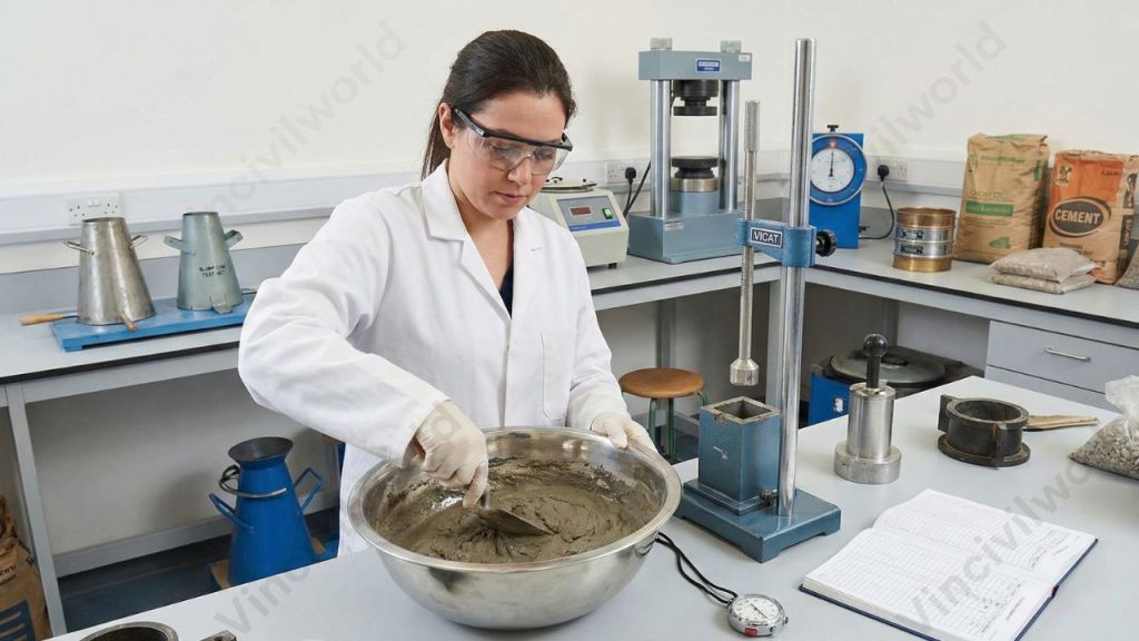
Apparatus used for consistency test on cement
The Vicat apparatus is used to determine the consistency of cement. It consists of a plunger, a movable rod weighing 300 g, graduated scale, non-porous plate, split mould and Vicat mould. The diameter of the plunger is 10mm and the length is 50mm. The graduate scale measures the depth of penetration. The Vicat mould is a cone frustum with 80 mm diameter. The test should be conducted at a standard temperature of 27 C. The humidity should be 65%. A stop clock is used to measure the time from the addition of water to the drying of cement. As per IS code, the time of gauging is not less than 3 minutes, nor more than 5 min.
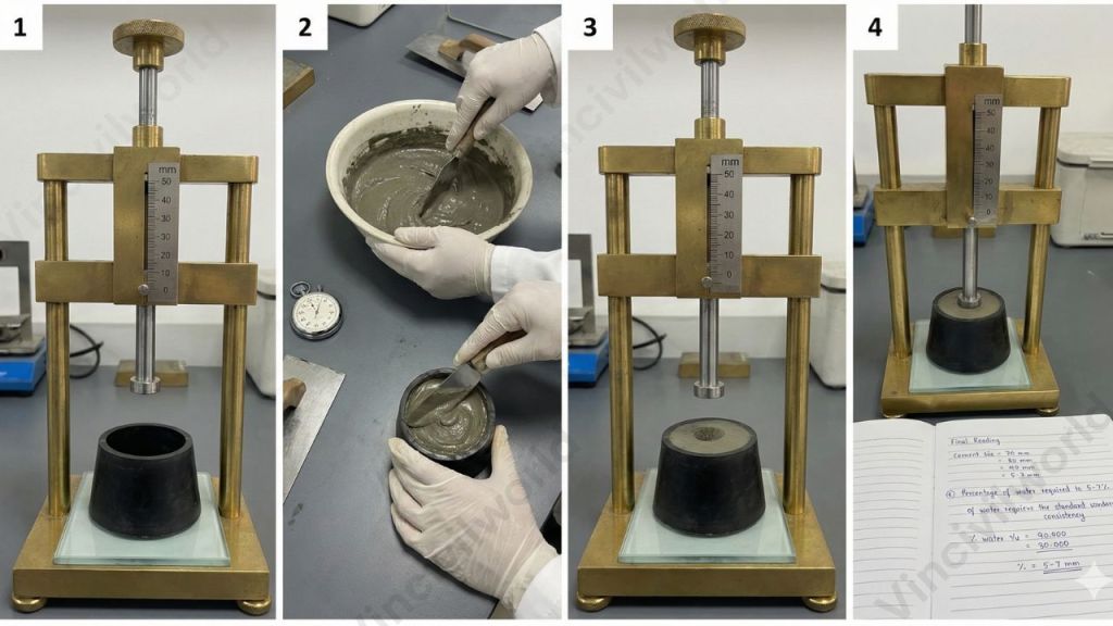
Procedure of consistency test for cement (As per IS 4031 Part 4)
Follow these steps when performing the consistency test under IS code:
- Use a clean Vicat apparatus (as per specification) with 10 mm-diameter plunger and standard mould resting on a non-porous base plate.
- Weigh a required quantity of cement and a proportionate amount of potable or distilled water.
- Begin gauging (mixing): mix cement and water thoroughly, and complete gauging within 3 to 5 minutes from addition of water. Ensure gauging is completed before any sign of setting occurs.
- Fill the Vicat mould with the fresh cement paste, rest mould on non-porous plate. Level the surface — remove excess paste, smooth the top. A light shake may be used to expel air bubbles.
- Lower the plunger gently so it just touches the paste surface, then release it to descent under its own weight (no external load).
- Observe the depth of penetration on the graded scale. If plunger stops such that it’s 5–7 mm above the bottom of mould — that paste has “standard consistency.”
- If the penetration depth is not within that range, discard paste; prepare a new paste with adjusted water content (increase or decrease water) and repeat until standard consistency is reached.
- Document the percentage water (by weight of cement) that achieved standard consistency — this becomes the “water for normal consistency” or “standard consistency water proportion.”
Calculation
The standard consistency is expressed in terms of the percentage of the quantity of added water to the weight of cement. The consistency of cement ranges from 26% to 33%.
Standard consistency = ( Quantity of water added / Weight of cement) x 100
Consistency of cement test procedure – Standards comparison
| Standard | Apparatus / Principle | Consistency Criterion / Penetration Depth | Notes / Use for Further Tests |
|---|---|---|---|
| IS 4031 (Part 4) | Vicat apparatus (10 mm dia. plunger, standard mould) | Plunger penetrates so that it stops 5–7 mm from the bottom of mould (i.e. ~33–35 mm from top) for standard / normal consistency ( | Basis for subsequent cement tests (setting time, soundness, strength) under Indian Code |
| ASTM C187 | Vicat-type penetration instrument / similar test method to determine water for “normal consistency” | Penetration per ASTM calibration (aims to find water percent giving normal consistency) | Used internationally / in labs following ASTM procedures; result used for further cement/concrete tests |
| BS EN 196‑3 (European / British standard) | Vicat apparatus for consistency and setting-time / soundness tests | Defines “standard consistence” via penetration depth per EN criteria; used before setting time & soundness tests | Common in European labs; ensures standard baseline for cement tests under EN / BS norms |
Precaution
We should take certain precautions before starting the test so that to obtain accurate results.
- Clean the Vicat mould properly and grease the inside surface
- Take immense care while attaching the plunger. Make sure it is vertical.
- Place the apparatus on a levelled surface.
- Maintain the standard temperature and humidity throughout the test.
Key Takeaways
- The consistency test of cement measures the required water for a workable paste, using the Vicat apparatus.
- This test is crucial for determining key properties like setting time, soundness, and compressive strength of cement.
- Standard consistency is reached when the plunger penetrates 5–7 mm from the bottom of the mould, ensuring proper hydration.
- Laboratory tests provide accurate assessments of cement quality, while field tests offer quick checks.
- Precautions are vital for accurate test results, including cleaning the apparatus and maintaining proper temperature and humidity.
Conclusion
In conclusion, the consistency test of cement is essential for maintaining quality and performance in concrete works. By determining the standard consistency of cement, engineers identify the exact water needed to create a uniform and workable paste. This value is crucial for reliable results in other major laboratory tests such as compressive strength, setting time, and soundness. The significance of standard consistency test of cement lies in ensuring proper hydration, which directly influences the strength, durability, and service life of structures. Using the Vicat apparatus, the test provides accurate and repeatable outcomes for both laboratories and field quality control. When the water–cement ratio is correctly maintained, concrete becomes safer, stronger, and more durable, supporting high-standard construction practices.