Category Archives: civil engineering

All the general details about civil engineering sector are given in the civil engineering category. Basic elements in civil engineering- Foundation is the lowermost part of the building. The building activity starts with digging the ground for foundation and then building it..

Column Jacketing: Types and Benefits Explained

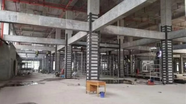
Column jacketing strengthens columns and improves their load-carrying capacity. Engineers add materials around existing columns to boost their strength, stiffness, and durability. This method helps repair and upgrade structures to meet modern safety standards. Jacketing of columns increases their resistance to seismic forces, making buildings safer during earthquakes. It also improves the columns’ performance under various loads. Engineers often use concrete jacketing, steel jacketing of columns, and fiber-reinforced polymer (FRP) jacketing for effective strengthening. Concrete jacketing involves applying reinforced concrete around existing columns to enhance their load-bearing capacity and structural integrity. It’s a cost-effective and reliable method for strengthening aging structures.

Column jacketing plays a crucial role in structural engineering. It extends the lifespan of structures and boosts their resilience. Engineers use this technique for strengthening bridges, buildings, and industrial structures. In the next sections, we will talk about the definition, significance, and various techniques of column jacketing.

  1. Definition of Jacketing
  2. Significance of Jacketing in Structural Engineering
  3. Applications of Jacketing in Retrofitting and Strengthening
  4. Understanding Column Jacketing
  5. Column Jacketing types
    1. Reinforced Concrete (RC) Column Jacketing
      1. Working Procedure of Reinforced Concrete Column Jacketing
      2. Advantages and disadvantages of Reinforcement Concrete Jacketing
    2. Steel Jacketing
      1. Working Procedure of Steel Jacketing of columns
      2. Advantages and Disadvantages of steel jacketing of columns
    3. Fiber Reinforced Polymer (FRP) Jacketing
      1. Working Procedure of Fiber Reinforced Polymer (FRP) Jacketing
      2. Advantages and Disadvantages of FRP jacketing
    4. Carbon Fiber Reinforced Polymer (CFRP) Jacketing
      1. Working Procedure of Carbon Fiber Reinforced Polymer Jacketing
      2. Advantages and Disadvantages of Carbon Fiber Reinforced Polymer Jacketing
  6. Comparison of FRP column Jacketing and CFRP Jacketing
    1. Composite Jacketing
      1. Advantages and disadvantages of Composite Jacketing
      2. Work Procedure for Composite Column Jacketing
      3. Advantages and Disadvantages of composite column jacketing
  7. Applications of Column Jacketing
  8. Key Takeaways
  9. Conclusion

Definition of Jacketing

Jacketing is a structural strengthening method. It involves adding materials around existing structural elements, like columns or beams. This process enhances their strength and durability. It usually involves using reinforced concrete, steel, or fiber-reinforced polymers (FRP). These materials increase the cross-sectional area and structural integrity of the member.

Significance of Jacketing in Structural Engineering

Jacketing is essential for retrofitting and strengthening structures damaged by aging, environmental factors, or increased load demands. It improves the strength and stiffness of structural elements like columns, beams etc., ensuring they meet current safety standards. Jacketing also enhances resilience to seismic forces, making structures safer during earthquakes.

Column Jacketing
Column Jacketing (Photo courtesy : https://www.horseen.com/product/steel-jacketing)

Applications of Jacketing in Retrofitting and Strengthening

Jacketing is commonly used for:

  • Repairing Deteriorated Structures: Restoring structural integrity damaged by corrosion or environmental factors.
  • Seismic Retrofitting: Increasing ductility and energy dissipation to resist earthquakes.
  • Increasing Load Capacity: Upgrading structural members to handle higher loads due to changing building usage.

The jacketing of columns is particularly important for structures located in seismic zones, where enhanced resilience is essential. In the upcoming sections, we will explore various column jacketing techniques and their applications.

Understanding Column Jacketing

Column jacketing is a popular technique used to strengthen and enhance the performance of columns. Engineers use this method to improve load-carrying capacity, stiffness, and durability. The primary purpose of column jacketing is to increase the strength of existing columns. It makes them more resilient against various loads. These loads include seismic forces. It also extends the lifespan of structures and helps them meet modern safety standards. Additionally, column jacketing is a cost-effective solution compared to rebuilding or replacing damaged structures.

Column jacketing is commonly used in several scenarios. Engineers often apply it to structures that show signs of deterioration due to aging or environmental factors. It is also used for retrofitting buildings and bridges to enhance their load-bearing capacity. Moreover, structures located in earthquake-prone areas gain significantly from this technique.

Steel jacketing of column

Overall, column jacketing is a reliable solution for enhancing structural safety and durability. Its effectiveness and versatility make it a preferred choice for repairing, retrofitting, and strengthening various types of structures.

Column Jacketing types

Column jacketing is a structural strengthening technique used to enhance the load-carrying capacity, durability, and seismic resistance of columns. Various techniques are employed based on material type and application requirements. The main types include:

  • Reinforcement Concrete Jacketing
  • Steel Jacketing
  • Fiber Reinforced Polymer (FRP) Jacketing
  • Carbon Fiber Reinforced Polymer (CFRP) Jacketing
  • Composite Jacketing

Reinforced Concrete (RC) Column Jacketing

Reinforced Concrete Jacketing is the most common method for strengthening columns. It involves adding a layer of reinforced concrete around the existing column, increasing its cross-sectional area and enhancing its load-carrying capacity. The extra concrete also improves the column’s stiffness, ductility, and resistance to seismic forces. RC Jacketing is widely used for retrofitting old structures and repairing damaged columns. This method is cost-effective and offers excellent fire resistance. However, it requires increased column size, which affects the building’s aesthetics and usable space.

RCC column Jacketing

Working Procedure of Reinforced Concrete Column Jacketing

  1. Surface Preparation: Clean and roughen the existing column surface to improve bonding.
  2. Reinforcement Installation: Place extra reinforcement bars around the column and securely anchor them to the existing column.
  3. Formwork Preparation: Install Formwork around the column, leaving adequate space for the concrete layer.
  4. Concrete Pouring: Pour high-strength or regular concrete into the Formwork and compact it properly.
  5. Curing: Allow the concrete to cure for the required period to achieve desired strength.
  6. Inspection: Remove the Formwork and inspect the finished jacket for defects.

Advantages and disadvantages of Reinforcement Concrete Jacketing

AdvantagesDisadvantages
Increases load-bearing capacity.Increases the size of the column, which reduces usable space.
Enhances ductility and seismic resistance.Heavyweight affects the structure’s overall weight.
Cost-effective and provides excellent fire resistance.Requires skilled labor and time for proper implementation.
Widely applicable for retrofitting and repairs.

Steel Jacketing

Steel Jacketing involves encasing columns with steel plates or sections to improve their strength and ductility. This method provides high tensile strength, excellent impact resistance, and increased load-bearing capacity. Steel jacketing is particularly effective for seismic retrofitting and enhancing the structural performance of deteriorated columns. Nevertheless, it needs regular maintenance to prevent corrosion. It is not suitable for environments with high moisture or chemical exposure.

Steel jacketing of columns

Working Procedure of Steel Jacketing of columns

  1. Surface Preparation: Clean the column’s surface to remove dirt, debris, and any loose materials.
  2. Steel Plate Fabrication: Cut steel plates or sections to the required dimensions, ensuring they fit snugly around the column.
  3. Installation of Steel Plates: Position the steel plates around the column. Secure them using bolts or welding. Make sure a tight fit to guarantee effective confinement.
  4. Grouting (if necessary): Inject grout between the steel jacket and the column surface. Fill any gaps. This ensures uniform load transfer.
  5. Corrosion Protection: Apply protective coatings to the steel surface to prevent corrosion and extend the jacket’s lifespan.

Advantages and Disadvantages of steel jacketing of columns

AdvantagesDisadvantages
Enhanced Strength and Ductility: Significantly increases the column’s load-bearing capacity and ductility, improving overall structural performance.Corrosion Susceptibility: Steel is prone to corrosion, especially in humid or aggressive environments, necessitating regular maintenance and protective measures.
Minimal Increase in Cross-Section: Provides significant strength gains without notably increasing the column’s size, preserving architectural aesthetics and usable space.Cost Considerations: Material and installation costs can be higher compared to other jacketing techniques.
Rapid Installation: The installation process is relatively quick, reducing downtime during retrofitting projects.Thermal Conductivity: Steel’s high thermal conductivity requires extra fireproofing measures to preserve structural integrity during fires.

Fiber Reinforced Polymer (FRP) Jacketing

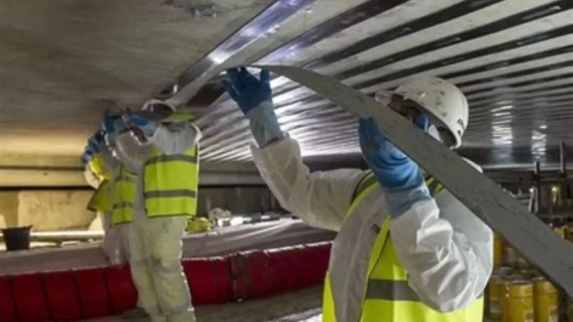
FRP Jacketing uses lightweight, high-strength composite materials. These materials are made of fibers such as carbon, glass, or aramid. They are embedded in a polymer matrix. This method offers superior strength, corrosion resistance, and minimal weight addition to the structure. FRP Jacketing enhances the column’s ductility and load-carrying capacity, making it highly effective for seismic retrofitting. It is easy to install, requires minimal maintenance, and does not significantly alter the appearance of the column. Nonetheless, it is relatively expensive and require additional fire protection measures in certain applications.

Fiber Reinforced polymer(FRP) Jacketing

Working Procedure of Fiber Reinforced Polymer (FRP) Jacketing

  1. Surface Preparation: Clean and smooth the column surface, removing any irregularities to guarantee proper adhesion.
  2. Primer Application: Apply a primer to the prepared surface to promote adhesion between the concrete and the FRP materials.
  3. Resin Application: Coat the primed surface with a layer of resin, serving as the bonding agent for the FRP fabric.
  4. FRP Wrapping: Wrap the resin-coated column with FRP fabric, ensuring proper alignment and tension to remove air pockets.
  5. Extra Resin Coating: Apply another layer of resin over the FRP wrap. This will fully saturate the fibers. It also ensures a strong bond.
  6. Curing: Allow the resin to cure as per the manufacturer’s recommendations, solidifying the FRP jacket.

Advantages and Disadvantages of FRP jacketing

AdvantagesDisadvantages
High Strength-to-Weight Ratio: Provides significant strength enhancement without adding considerable weight to the structure.Cost: FRP materials can be expensive, increasing the overall project cost.
Corrosion Resistance: FRP materials are inherently resistant to corrosion, making them ideal for harsh environmental conditions.Fire Resistance: FRP materials have limited fire resistance, requiring extra protective measures in fire-prone areas.
Minimal Section Enlargement: The thin profile of FRP jackets preserves the original dimensions of the column, maintaining aesthetics.UV Sensitivity: Some FRP materials degrade under prolonged UV exposure, necessitating protective coatings for outdoor use.
Ease of Installation: The lightweight and flexible nature of FRP materials facilitates quick and straightforward installation.Adhesion Sensitivity: Effectiveness heavily relies on proper surface preparation and application techniques.

Carbon Fiber Reinforced Polymer (CFRP) Jacketing

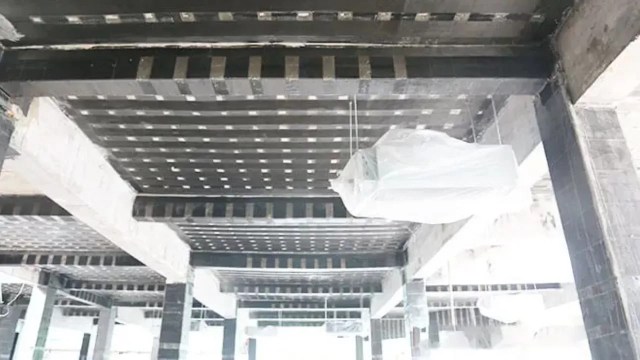
Carbon Fiber Reinforced Polymer (CFRP) Jacketing CFRP Jacketing is a specialized form of FRP Jacketing. It uses carbon fibers for reinforcement. It offers exceptional tensile strength, lightweight properties, and excellent corrosion resistance. CFRP jacketing is widely used for enhancing the seismic resistance and structural performance of columns. It is easy to apply and does not require heavy equipment, making it ideal for structures with limited access. However, CFRP materials are expensive, have poor fire resistance, and are sensitive to ultraviolet light. They are also brittle under certain loading conditions.

Carbon Fiber Reinforced Polymer Jacketing

Working Procedure of Carbon Fiber Reinforced Polymer Jacketing

  1. Surface Preparation: Thoroughly clean and smooth the column surface to ensure optimal adhesion of the CFRP materials.
  2. Primer Application: Apply a suitable primer to the prepared surface. This promotes strong bonding between the concrete and the CFRP materials.
  3. Resin Application: Spread a layer of resin over the primed surface, serving as the adhesive for the CFRP fabric.
  4. CFRP Wrapping: Wrap the resin-coated column with CFRP fabric, ensuring tight wrapping and the elimination of air pockets.
  5. Additional Resin Coating: Apply another resin layer over the CFRP wrap. This will fully saturate the fibers. It will also ensure a robust bond.
  6. Curing: Allow the resin to cure according to the manufacturer’s guidelines, solidifying the CFRP jacket.

Advantages and Disadvantages of Carbon Fiber Reinforced Polymer Jacketing

AdvantagesDisadvantages
High Strength-to-Weight Ratio: CFRP offers exceptional strength enhancement with minimal weight addition, preserving structural efficiency.High Cost: CFRP materials are expensive, significantly increasing project costs compared to other jacketing methods.
Corrosion Resistance: Excellent resistance to corrosion, making it suitable for use in harsh and corrosive environments.Limited Fire Resistance: CFRP is vulnerable to high temperatures, requiring additional fireproofing measures.
Ease of Installation: Lightweight and flexible nature allows for quick and efficient installation.Surface Preparation Requirement: Proper surface preparation is essential for effective bonding, demanding meticulous procedures.
Durability and Long Lifespan: CFRP has a long lifespan with minimal maintenance requirements.UV Sensitivity: Prolonged exposure to ultraviolet rays can degrade the material, requiring protective coatings.
Minimal Section Enlargement: Enhances strength without significantly altering the column’s dimensions, preserving aesthetics.Brittle Failure Mode: CFRP can exhibit sudden brittle failure without prior warning if overloaded.

Comparison of FRP column Jacketing and CFRP Jacketing

AspectFRP JacketingCFRP Jacketing
Material CompositionMade of fibers like glass, aramid, or carbon embedded in a polymer matrix.Specifically made of carbon fibers embedded in a polymer matrix.
StrengthProvides good strength enhancement.Offers superior strength-to-weight ratio and stiffness.
WeightLightweight but heavier than CFRP.Extremely lightweight and strong.
Corrosion ResistanceHigh corrosion resistance, especially with glass or aramid fibers.Excellent corrosion resistance, especially suitable for harsh environments.
CostGenerally more affordable.More expensive due to the high cost of carbon fibers.
Application AreasSuitable for general structural strengthening.Ideal for high-performance applications requiring exceptional strength and stiffness.
Fire ResistanceLimited fire resistance, require additional protection.Limited fire resistance, but often better than other FRP types.
InstallationEasy to install due to flexibility.Slightly more challenging to handle due to stiffness.
DurabilityGood durability under most conditions.Superior durability and long-term performance.

Composite Jacketing

Composite Jacketing Composite Jacketing involves combining different materials, such as steel and FRP, to improve the overall performance of columns. This method provides enhanced strength, ductility, and durability. Composite Jacketing is effective for retrofitting columns exposed to harsh environmental conditions. However, it requires careful material selection and design to achieve the desired performance.

Retrofitting
Composite Jacketing

Advantages and disadvantages of Composite Jacketing

AdvantagesDisadvantages
Enhanced Strength and Ductility: Combining materials like steel and FRP improves load-bearing capacity and ductility.Complex Design Requirements: Effective implementation requires meticulous design and compatibility assessment.
Durability: Provides improved resistance to environmental factors like corrosion, impact, and wear.Higher Cost: Using multiple materials can increase project costs, especially when high-quality materials are used.
Versatility: Suitable for various applications, including seismic retrofitting and rehabilitation.Installation Complexity: Installation may require specialized skills and techniques for effective application.
Improved Structural Performance: Achieves better overall performance compared to using a single material.Bonding Issues: Proper bonding between different materials is essential for effective load transfer.
Minimal Aesthetic Impact: Can maintain the original structural appearance when applied properly.Maintenance Requirements: Require regular inspection and maintenance to ensure continued performance.

Work Procedure for Composite Column Jacketing

Assessment and Design: Inspect the column for damage. Design the composite jacketing system based on structural needs and environmental conditions. Select suitable materials (e.g., Steel + FRP) for compatibility and load requirements.
Surface Preparation: Clean the column surface to remove dirt and coatings. Repair cracks or weak spots for a smooth bonding surface.
Steel Jacketing (If Applicable): Install steel plates around the column using anchors or bolts. Weld or bolt plates for proper fitting.
FRP Jacketing Application: Cut FRP sheets to size. Apply resin or adhesive to the column and sheets. Wrap sheets around the column with proper alignment and overlap. Allow curing.
Finishing: Apply protective coating if needed. Inspect for bonding and alignment.
Quality Control: Perform NDT or load tests to ensure effectiveness. Regularly inspect and maintain the jacketed columns.

Advantages and Disadvantages of composite column jacketing

AdvantagesDisadvantages
High Strength-to-Weight Ratio: CFRP offers exceptional strength enhancement with minimal weight addition, preserving structural efficiency.High Cost: CFRP materials are expensive, significantly increasing project costs compared to other jacketing techniques.
Corrosion Resistance: Excellent resistance to corrosion, making it suitable for use in harsh and corrosive environments.Limited Fire Resistance: CFRP is vulnerable to high temperatures, requiring extra fireproofing measures.
Ease of Installation: Lightweight and flexible nature allows for quick and efficient installation.Surface Preparation Requirement: Proper surface preparation is essential for effective bonding, demanding meticulous procedures.
Durability and Long Lifespan: CFRP has a long lifespan with minimal maintenance requirements.UV Sensitivity: Prolonged exposure to ultraviolet rays can degrade the material, requiring protective coatings.
Minimal Section Enlargement: Enhances strength without significantly altering the column’s dimensions, preserving aesthetics.Brittle Failure Mode: CFRP can exhibit sudden brittle failure without prior warning if overloaded.

Applications of Column Jacketing

  • Seismic retrofitting of buildings.
  • Strengthening deteriorated or damaged columns.
  • Upgrading structures to meet new load requirements.
  • Corrosion protection in harsh environments.
  • Enhancing fire resistance.
  • Repairing bridges, industrial structures, and marine facilities.
  • Preserving historical structures.
  • Strengthening industrial plants and parking structures.
  • Reinforcing offshore platforms.
  • Improving structural performance and durability.

Key Takeaways

  • Column Jacketing is a structural strengthening technique used to enhance load capacity, durability, and seismic resistance of columns.
  • Types of Jacketing: Includes Steel Jacketing, Concrete Jacketing, FRP Jacketing, CFRP Jacketing, and Composite Jacketing.
  • Applications: Widely applied in seismic retrofitting, corrosion protection, industrial structures, bridges, and historical building preservation.
  • Advantages: Increased strength, durability, corrosion resistance, and fire protection.
  • Disadvantages: High cost, complex installation, maintenance needs, and potential aesthetic impact.
  • Work Procedure: Involves assessment, surface preparation, installation, finishing, and quality control.
  • Quality Control: Non-destructive testing and regular inspection ensure long-term performance.
  • Best Choice: Selecting the appropriate method depends on structural requirements, environmental conditions, and budget.

Conclusion

Column jacketing is an effective structural strengthening technique that enhances the durability, load-bearing capacity, and seismic resistance of columns. Various methods like Steel, Concrete, FRP, CFRP, and Composite Jacketing offer unique benefits. They also have limitations. It is essential to select the most suitable approach based on specific structural requirements and environmental conditions. Proper assessment, installation, and quality control are crucial to achieving optimal performance. As infrastructure continues to age and face new challenges, column jacketing provides a valuable solution. It aids in the rehabilitation, retrofitting, and protection of critical structural elements.

Slipform Shuttering – Types, Techniques Applications

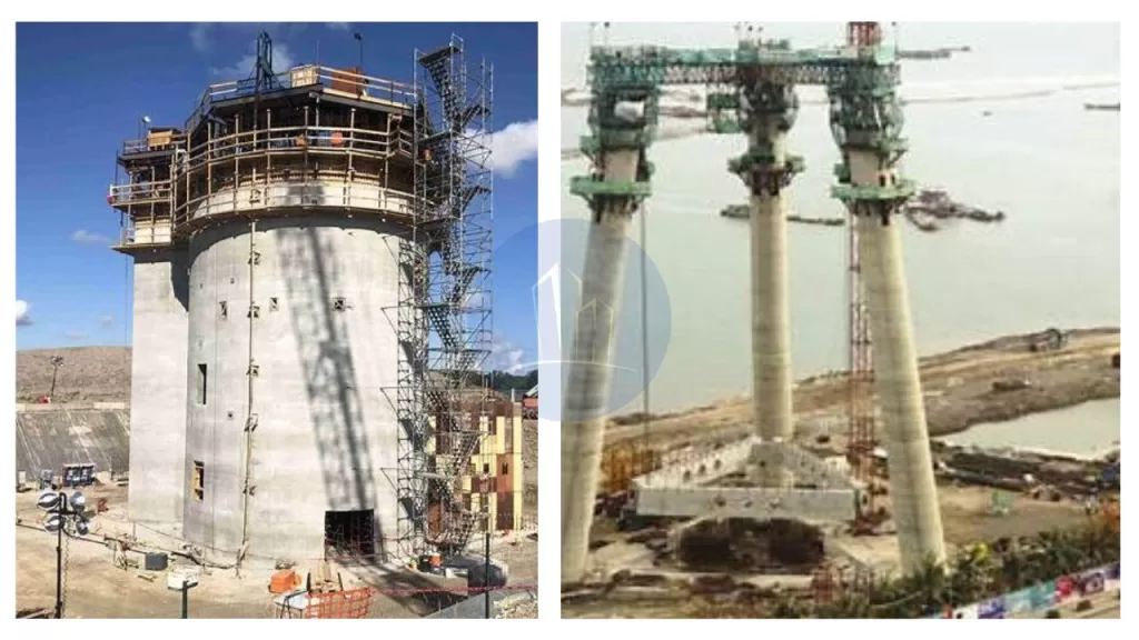
Slipform shuttering is a continuous construction method. In this method, concrete is poured into a continuously moving formwork. This allows for the seamless creation of vertical structures. This technique, known as slipforming, enables the efficient construction of tall edifices such as silos, chimneys, and core walls in high-rise buildings. By employing slipform formwork, builders can achieve monolithic structures without horizontal joints. This method enhances the overall strength and durability of the construction.

The slipform formwork construction process involves the gradual and steady upward movement of the formwork system. This movement is synchronized with the setting rate of the concrete. This ensures that as the formwork ascends, the concrete below has gained sufficient strength to support itself. The continuous nature of slipform shuttering not only accelerates the construction timeline but also reduces labor costs and minimizes the need for scaffolding, making it a preferred choice for large-scale vertical constructions.

The blog will explore the definition and principles of Slipform shuttering, its key components, and the process of slipforming. We will highlight its advantages, common applications, and critical considerations for effective use. Additionally, we will discuss how Slipform formwork construction enhances efficiency and provide insights into best practices for successful implementation.

  1. What is Slipform Shuttering?
    1. Significance and Development
  2. Slipform formwork construction
    1. Continuous Pouring and Synchronized Upward Movement
    2. Importance of Concrete Setting Time
  3. Historical Development of Slipform formwork construction
  4. Key components of slipform system
  5. Types of slipform shuttering
    1. Vertical Slipform
    2. Horizontal Slipform shuttering
    3. Tapered Slipform shuttering
    4. Conical Slipform shuttering
    5. Egg-shaped Slipform
    6. Cantilever Slipform
  6. Advantages of Slipform Formwork Construction
  7. Challenges and disadvantages of Slipform Shuttering
  8. Applications of Slipform shuttering
  9. Advancements in slipform construction
  10. Conclusion

What is Slipform Shuttering?

Slipform shuttering is an advanced construction technique. It enables the continuous pouring of concrete for vertical structures like silos, chimneys, and high-rise cores. The method employs slipform formwork construction, where the formwork system moves steadily upward, synchronized with the concrete’s setting time. This ensures seamless, monolithic structures without horizontal joints.

Significance and Development

The development of slipforming revolutionized construction by enhancing efficiency and reducing project timelines. This method eliminates the need for scaffolding, minimizes labor costs, and ensures structural integrity. Slipform shuttering has become integral in modern construction. It is especially useful for projects requiring tall, uniform structures. This is due to its ability to streamline processes while maintaining high-quality results.

Slipform formwork construction

The slipform formwork construction method basically rely on the following factors

Slipform formwork construction

Continuous Pouring and Synchronized Upward Movement

In slipform shuttering, concrete is poured continuously into a moving formwork system, which climbs steadily as the concrete sets. This synchronized upward movement ensures a seamless structure, eliminating horizontal joints and enhancing strength.

Importance of Concrete Setting Time

The climbing speed of the formwork is carefully calibrated to match the concrete’s setting time. If the formwork ascends too quickly, the concrete may deform due to insufficient strength. Conversely, if it moves too slowly, delays and uneven surfaces can occur. Maintaining this balance is crucial for structural integrity and efficiency. Proper synchronization is essential. It ensures that the concrete beneath the formwork gains enough strength to support its weight. It also needs to withstand construction loads during the process.

Historical Development of Slipform formwork construction

Slipforming has a rich history dating back to the early 20th century. The first slipform systems were primarily used for concrete roads and canals. Over the years, significant technological advancements have led to the development of sophisticated slipform systems that can handle complex structures and challenging environments. Some key milestones in the development of slipforming include:

  • Early 20th Century: The first rudimentary slipform systems were used for road and canal construction.
  • Mid-20th Century: The introduction of hydraulic systems and improved concrete technology paved the way for more efficient and versatile slipform systems.
  • Late 20th Century: The development of computer-controlled slipform systems further enhanced precision and accuracy.
  • 21st Century: Continued advancements in automation, robotics, and material science are leading to even more sophisticated and sustainable slipform systems.

Key components of slipform system

In slipform shuttering, several key components work together to facilitate continuous concrete construction:

  • Formwork Panels: These vertical molds shape the concrete as it’s poured, ensuring the desired dimensions and surface finish. As the formwork ascends, the panels move upward at a controlled rate, allowing the structure to rise seamlessly.
  • Jacking Systems: Hydraulic or pneumatic jacks lift the formwork incrementally. They support the formwork, platforms, crew, and withstand the hydrostatic pressure of the fresh concrete. The placement of jacks depends on vertical forces and lateral pressures, ensuring stability during the slipforming process.
  • Working Platforms: These platforms provide safe and accessible areas for workers to perform tasks such as pouring concrete, monitoring alignment, and managing reinforcement. They move in tandem with the formwork, maintaining consistent working conditions.
  • Support Structures: Elements like yokes and whalers distribute loads from the formwork and jacking systems, maintaining structural integrity. Yokes connect the formwork to the jacks, while whalers reinforce the formwork panels, ensuring even pressure distribution.
  • Concrete Placement Equipment: Conveying systems like concrete pumps or chutes ensure continuous concrete delivery to the formwork.
  • Vibration System: Compacts the concrete within the formwork, eliminating air pockets and ensuring a uniform density.

The cohesive interaction of these components enables the efficient construction of vertical structures. These structures are continuous and without joints. This process enhances both speed and structural integrity.

Types of slipform shuttering

Slipform shuttering encompasses several types, each tailored to specific construction needs. The most common types of slipform shuttering types are as follows

  • Vertical slipform shuttering
  • Horizontal Slipform shuttering
  • Tapered slipform
  • Conical slipform
  • Egg shaped slipform
  • Cantilever type

Vertical Slipform

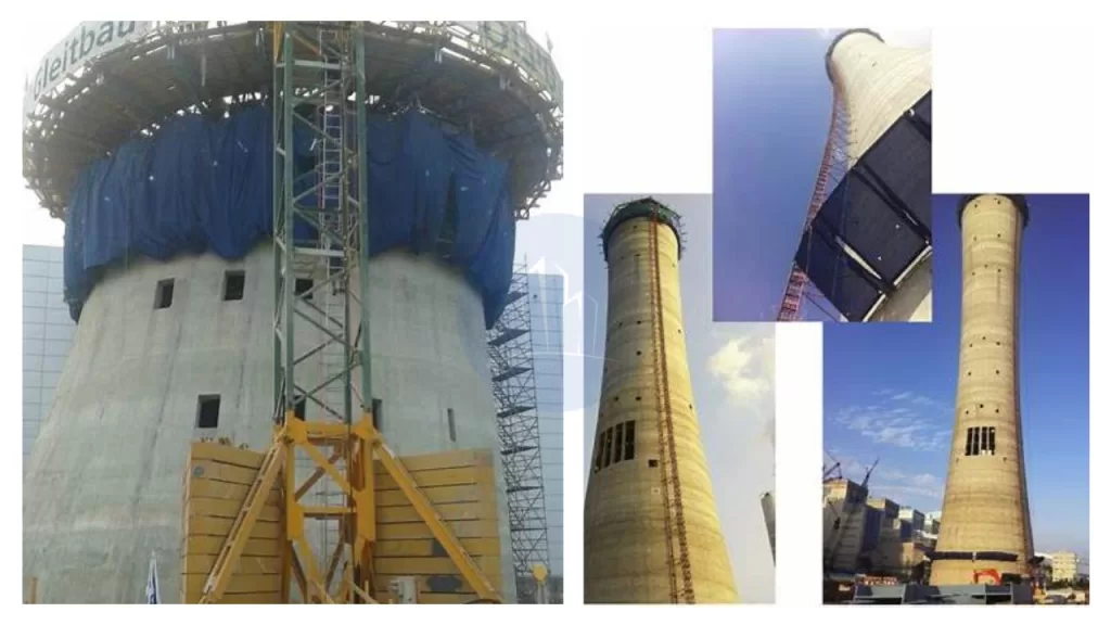
Builders use vertical slipform to construct tall structures, such as silos, chimneys, or towers. They employ a moving formwork system that continuously ascends as they pour concrete. Workers gradually raise the formwork using hydraulic jacks, ensuring a smooth and consistent construction process.This method allows for the creation of vertical concrete structures without the need for scaffolding or traditional formwork systems. As the concrete sets, the formwork slips upwards, maintaining a uniform shape. Vertical slipform is efficient for projects requiring rapid construction, offering enhanced safety and reduced labor costs. It also ensures high-quality finishes and precise dimensions, making it suitable for large-scale industrial and infrastructure projects.

Slipform shuttering /slipforming

Horizontal Slipform shuttering

This technique is utilized in constructing horizontal structures such as road pavements and bridge decks. It allows the formwork to move horizontally. This movement enables continuous concrete placement along the structure’s length. Workers use horizontal slipform to create continuous concrete elements such as pavements, curbs, drainage channels, and safety barriers. This method involves the extrusion of concrete in situ, allowing for uninterrupted casting of long sections.

A specially designed machine has a mold with the required dimensions. It is equipped with vibrators for concrete compaction and moves forward at a controlled rate. The machine powers itself and mounts on wheels or tracks, ensuring stability during operation. As workers pour concrete from the rear of the machine, it becomes self-supporting. The machine follows a prefixed guide wire to achieve the correct line and level. This approach offers advantages such as speed, the ability to produce monolithic structures, and operational economy.

Horizontal slipform formwork construction

Tapered Slipform shuttering

This method is designed for structures with varying cross-sections, such as conical chimneys and cooling towers. It adjusts the formwork dimensions during the slipforming process. This adjustment achieves the desired tapering effect.

Builders use tapered slipform to create structures with a gradually narrowing shape. Examples include chimneys, cooling towers, and tall industrial structures. They employ movable formwork that adjusts in size as it rises, allowing for a tapered design. Similar to vertical slipform, workers pour concrete continuously as the formwork rises, typically using hydraulic jacks or other lifting mechanisms. Engineers design the formwork carefully to accommodate the structure’s changing cross-section, ensuring a precise and smooth taper.This method offers efficiency in construction, as it reduces the need for complex scaffolding and allows for a seamless, uniform finish. Tapered slipform is ideal for projects requiring strong, stable, and visually appealing tapered structures.

shuttering
Tapered construction

Conical Slipform shuttering

Builders use conical slipform to construct structures with a conical shape, such as cooling towers or silos. They use a moving formwork that continuously ascends as workers pour concrete. Workers shape the formwork to create a gradual narrowing toward the top. This process forms the cone. Workers raise the formwork using hydraulic jacks or other lifting mechanisms as the concrete cures, ensuring a smooth and consistent structure. This approach is highly efficient, as it eliminates the need for scaffolding and enables continuous, uninterrupted pouring. Conical slipform offers precise control over the shape and finish. It is ideal for large-scale, high-strength structures with conical geometry. It also reduces labor costs and construction time.

Egg-shaped Slipform

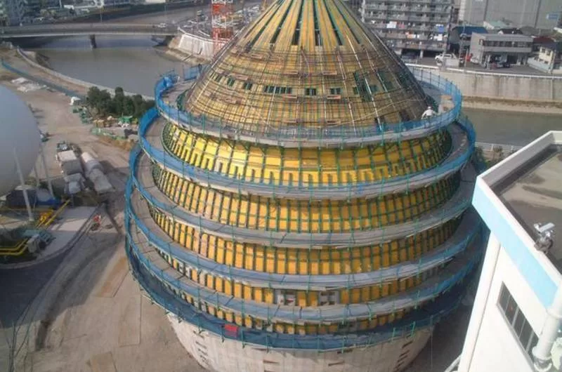
Engineers use egg-shaped slipform to create structures with an elliptical or egg-like shape. These structures include certain types of silos, industrial towers, and water or wastewater treatment facilities. They utilize specially designed formwork that moves vertically as workers pour concrete continuously. The formwork is shaped to create the unique, rounded profile of the egg shape, gradually narrowing at the top. Workers raise the formwork using hydraulic jacks or other lifting mechanisms, ensuring smooth and consistent construction. Egg-shaped slipform provides benefits like efficient construction with minimal labor, reduced material waste, and precise control over the shape. This technique is particularly suitable for structures requiring unique, aerodynamic designs, offering both functional and aesthetic advantages.

Egg shaped slipform shuttering
Egg shaped slip form Image courtesy : https://www.rsb.info/schalungen-schalungssysteme/

Cantilever Slipform

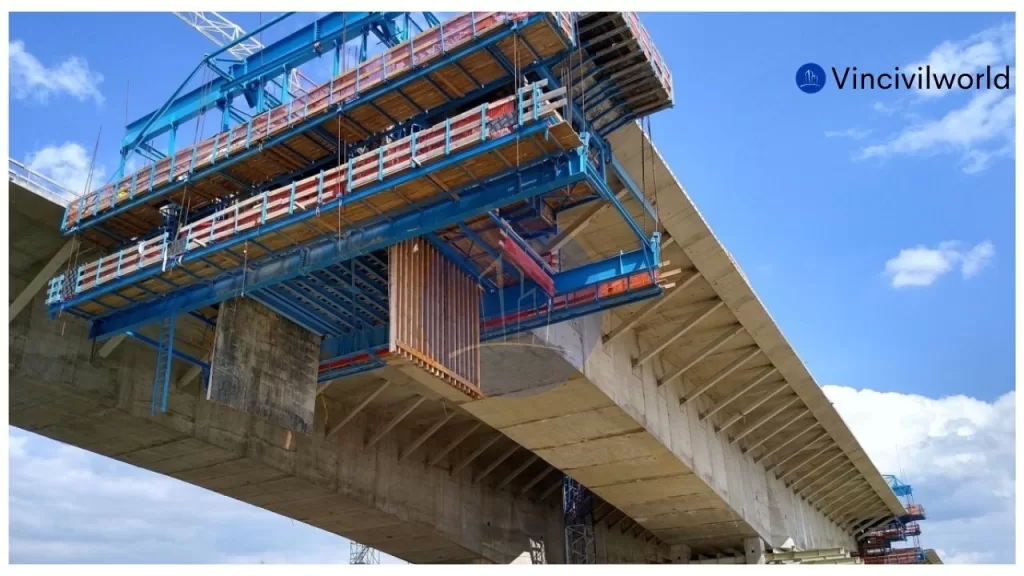
This method enables builders to construct structures that extend horizontally beyond their supports. These structures include certain bridge segments. It also allows them to build overhanging elements without the need for additional support scaffolding.

In cantilever slipform, construction teams use a method to build structures with an overhanging or projecting shape, such as bridges, dams, and tall towers. They gradually move the formwork system upwards while pouring concrete continuously. The structure itself supports the formwork, which extends outward as it rises, creating a cantilever effect. This technique is ideal for projects where workers have limited access to both sides of the structure or when constructing from the top down. Cantilever slipform ensures a precise and smooth finish, with high structural integrity. It reduces the need for scaffolding or external supports, making it an efficient and cost-effective method for large-scale projects that require overhanging sections or complex geometries.

Cantilever slipforming

Engineers design each type of slipform shuttering to meet specific architectural and structural demands, enhancing construction efficiency and quality.

Advantages of Slipform Formwork Construction

Slipform shuttering offers several advantages in construction, making it a preferred method for certain types of structures. Some key benefits include:

  • Speed and Efficiency: Continuous pouring and raising of formwork allow for faster construction, reducing overall project timelines.
  • Cost-Effective: It minimizes labor costs by eliminating the need for scaffolding and extensive formwork, resulting in a more economical process.
  • High Quality: The method provides a smooth, consistent finish with high precision and uniformity in dimensions.
  • Safety: With less reliance on manual labor and scaffolding, slipform offers enhanced safety for workers during construction.
  • Minimal Material Wastage: The continuous nature of the process reduces material waste, making it more environmentally friendly.
  • Reduced Need for Supervision: Automated or semi-automated systems reduce the need for constant supervision, leading to better management of resources.
  • Versatility: Suitable for a variety of structures, including vertical, tapered, conical, and curved shapes, making it adaptable to different project requirements.
  • Monolithic Structures: Slipform allows for the construction of monolithic concrete elements, improving the structural integrity of the finished project.
  • Durability: The seamless construction process ensures strong, durable structures with fewer weak points.
  • Reduced Labor Dependency: The method relies on machinery, reducing the need for large labor forces and improving construction consistency.

Challenges and disadvantages of Slipform Shuttering

While slipforming offers numerous advantages, it also presents several challenges that need to be carefully managed to ensure successful implementation.

  • High Initial Setup Costs: The machinery, formwork, and equipment required for slipforming can be costly. This leads to high upfront investments. Such investments may not be feasible for smaller projects.
  • Complexity in Design: Formwork design must be highly precise and adaptable to varying shapes and sizes. Skilled engineering and planning are necessary to meet specific project requirements.
  • Skilled Labor: Skilled operators are crucial for proper alignment. They ensure smooth operation. The availability of experienced personnel is essential for effective slipforming.
  • Concrete Quality Control: Maintaining consistency in concrete mix and quality is vital. Any variation in material quality, mix ratios, or curing methods can negatively impact the structure’s integrity.
  • Weather Conditions: Unfavorable weather, such as heavy rain or freezing temperatures, can disrupt the slipforming process. It can also affect concrete curing. This necessitates careful planning and adjustments.
  • Continuous Supervision: Despite automation, slipforming systems still require constant monitoring to address potential malfunctions or adjustments during the process.
  • Site Access: Limited access to construction sites can make it challenging to transport the necessary machinery and materials.

By addressing these challenges with proper planning, slipforming can be an efficient construction method. Skilled labor and risk management also contribute to its effectiveness.

Applications of Slipform shuttering

Slipform shuttering is a versatile construction technique. It is employed across various industries for its efficiency. It also has the ability to create continuous, seamless structures. Key applications include:

  • High-Rise Building Cores: Slipform is ideal for constructing the core walls of high-rise buildings. It enables rapid and uniform construction of elevator shafts and stairwells.
  • Chimneys and Cooling Towers: The method is extensively used for building tall, tapered structures like chimneys and cooling towers. It ensures consistent quality and structural integrity.
  • Silos and Tanks: Slipform facilitates the construction of large storage silos and tanks. It provides a cost-effective and efficient solution for industries requiring bulk storage.
  • Bridges: Bridge piers and abutments benefit from slipform construction, allowing for continuous pouring and reducing the need for formwork stripping.
  • Roadways and Pavements: In highway construction, slipform is used to build continuous pavements, curbs, and barriers. This technique enhances construction speed. It also improves surface uniformity.
  • Dams: Slipform technology is applied in constructing concrete-faced dams, enabling efficient and continuous pouring of concrete.
  • Water Towers: The technique is employed to construct the walls of water towers, ensuring uniformity and structural strength.
  • Offshore Structures: Slipform is utilized in the construction of offshore platforms and structures, providing a robust and continuous concrete shell.

These applications highlight the versatility and efficiency of slipform shuttering in modern construction projects.

Advancements in slipform construction

Advancements in automation and real-time monitoring have significantly enhanced slipform shuttering processes. Integrating automated systems with real-time concrete monitoring allows for precise adjustments during construction, ensuring optimal curing conditions and structural integrity. By embedding sensors within the concrete, teams can monitor parameters like temperature and strength, enabling timely interventions and reducing delays.

Additionally, innovations in materials and formwork technology have improved efficiency and safety. Modern formwork systems are designed to be cost-effective, lightweight, reusable, and easy to assemble and dismantle. These advancements contribute to faster construction times and enhanced structural performance.

Collectively, these developments modernize construction practices by increasing efficiency, reducing costs, and ensuring higher-quality outcomes.

Conclusion

Slipform shuttering has revolutionized modern construction by enabling continuous, efficient, and precise building of complex structures. Its key benefits include faster construction timelines and reduced labor costs. It also minimizes material wastage and improves safety by eliminating the need for scaffolding. The method ensures a smooth, uniform finish. It is highly adaptable to various structural shapes. These include high-rise cores, chimneys, silos, cooling towers, bridges, and dams. It is particularly effective for projects requiring repetitive, large-scale concrete pouring. Slipform shuttering reduces manual labor. It optimizes resource use and modernizes construction practices. These improvements make construction practices more cost-effective, environmentally friendly, and precise. Its efficiency and scalability are crucial for meeting the demands of large infrastructure projects in today’s fast-paced construction industry.


Welding Procedure Specification (WPS) : The Key to Flawless Welding

A Welding Procedure Specification (WPS) is essential for achieving precise and high-quality welds. It outlines the steps, parameters, and guidelines that ensure consistent and flawless welding results. But what is a WPS in welding? Simply put, it’s a detailed document that defines the weld specification, including joint configurations, welding process, and filler material. Understanding what a welding procedure specification entails is crucial for both novice and experienced welders. By mastering the principles of a WPS, you can achieve reliable, high-quality welds every time. In this guide, we explore what WPS in welding means, its components, and how it ensures superior performance. Let’s unlock the secrets to perfect welds with this essential tool.

  1. What is Welding Procedure Specifications (WPS) in Welding ?
  2. Components of a Welding Procedure Specification
  3. Understanding Welding Codes and Standards
  4. Advantages of WPS
  5. How to develop a Welding Procedure Specification ?
    1. Identifying Project Requirements
    2. Selecting Welding Parameters and Techniques
    3. Documenting the WPS
    4. Review and Validation Process
    5. Conducting Trial Runs and Mock Welds
    6. Finalizing the WPS
  6. Preparing the Base Metal for Welding
    1. Cleaning the Base Metal
    2. Assessing the Joint Fit-Up
    3. Controlling Base Metal Temperature
  7. Selecting the Right Welding Process for Your Project
  8. Essential Variables and Their Impact on WPS
  9. Qualifying a Welding Procedure Specification
  10. Common Mistakes to Avoid in Welding Procedure Specification Development and Implementation
  11. Types of Welding Procedure Specifications
  12. Conclusion

What is Welding Procedure Specifications (WPS) in Welding ?

A Welding Procedure Specification (WPS) is the foundation of successful welding operations. It ensures every weld is precise, consistent, and of high quality. A clear WPS outlines specific processes, materials, and techniques for the welder to follow. This guidance enhances weld quality while promoting safety, efficiency, and adherence to industry standards. Without a proper welding procedure specification, defects, increased costs, and workplace hazards become common challenges.

But what is a WPS in welding? It is a detailed document that plays a critical role in quality control and assurance. A Work Procedure Specification serves as a reference during inspections and audits, ensuring compliance with relevant weld specifications and standards. By following a welding procedure specification, organizations can reduce non-conformance risks, rework, and project delays.

Additionally, a Work Procedure Specification helps train welders, ensuring best practices are consistently followed across teams. It also reassures clients and stakeholders about the reliability of a project. Understanding what a WPS in welding entails demonstrates professionalism and builds trust. Investing in a robust WPS not only benefits current projects but also strengthens long-term business success.

A welding procedure specification is much more than a guideline—it’s a vital tool for quality, safety, and industry excellence.

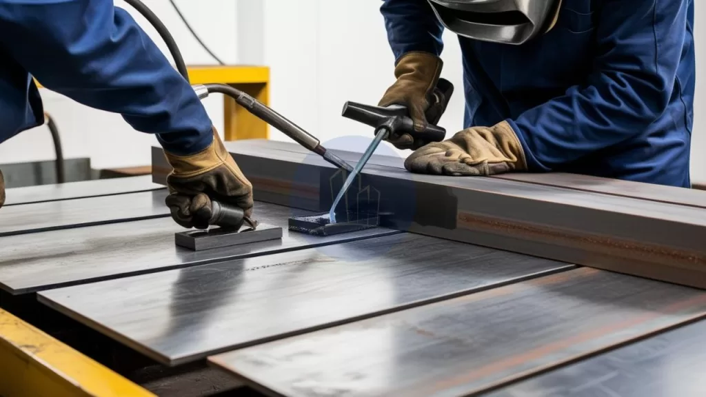
Welding procedure Specification (WPS)

Components of a Welding Procedure Specification

A Welding Procedure Specification (WPS) is a detailed guide that defines the welding process. It includes critical components such as the welding method, base and filler materials, preheat and interpass temperatures, and post-weld heat treatment requirements. Each section of the WPS provides clear and detailed instructions, ensuring welders understand the exact parameters they must follow.

One essential part of a WPS is identifying the materials. It specifies the grade, type, and thickness of the base metal along with the correct filler metal. These materials directly affect the welding process and the quality of the final weld. By choosing compatible materials and documenting them in the WPS, welders can minimize defects like cracking or incomplete fusion. Understanding what is a welding procedure specification ensures welders follow proper practices.

A WPS also outlines welding parameters and techniques. It includes details like position, voltage, amperage, travel speed, and shielding gas composition. Each of these factors is crucial to achieving high-quality welds. Clear documentation ensures consistent results across projects and welders. Knowing what is a WPS in welding and adhering to it enables precision and reliability. A well-crafted WPS is the backbone of any successful welding operation.

Understanding Welding Codes and Standards

Welding codes and standards play a crucial role in the creation and execution of Welding Procedure Specifications (WPS). These codes are set by organizations such as the American Welding Society (AWS). They also include the American Society of Mechanical Engineers (ASME) and the International Organization for Standardization (ISO). These organizations provide essential guidelines for different welding applications. A deep understanding of these codes is vital for ensuring compliance and achieving high-quality welds.

Each welding code specifies requirements related to materials, processes, testing, and quality control. For example, the AWS D1.1 code governs structural welding of steel, while ASME Section IX outlines qualifications for welding and brazing. Knowledge of these codes enables professionals to develop Welding Procedure Specifications. These specifications meet the necessary standards. This ensures their work is recognized within the industry.

Adhering to welding codes and standards is also critical for the safety and reliability of welded structures. Non-compliance can lead to catastrophic failures, risking injury, loss of life, and significant financial consequences. Welders can ensure the integrity and safety of their projects by integrating the appropriate welding codes into the Welding Procedure Specifications. This protects both themselves and their teams. Additionally, it strengthens the credibility of their work with clients and regulatory authorities.

Advantages of WPS

A Welding Procedure Specification (WPS) is essential for ensuring consistent, high-quality, and safe welding practices. It provides clear guidelines that help meet industry standards and optimize welding efficiency.

  • Ensures consistency in welding practices, leading to reliable and repeatable results.
  • Guarantees compliance with industry standards (e.g., AWS, ASME) for regulatory acceptance.
  • Improves safety by specifying proper techniques, material requirements, and treatments.
  • Supports quality assurance through clear reference for inspectors and engineers.
  • Ensures traceability of materials, processes, and testing methods for future audits.
  • Increases efficiency by reducing errors, minimizing rework, and streamlining training for welders.
Welding procedure Specification (WPS)

How to develop a Welding Procedure Specification ?

Creating a Welding Procedure Specification (WPS) requires a systematic approach that involves gathering information, analyzing variables, and documenting processes.

Identifying Project Requirements

The first step in creating a Welding Procedure Specification (WPS) is to identify the specific requirements of the project. This involves determining the materials involved, the welding process to be used, and any relevant codes and standards. Collaboration with project stakeholders, including engineers and quality assurance personnel, ensures that all necessary considerations are included.

Selecting Welding Parameters and Techniques

After defining the project requirements, the next phase involves selecting the appropriate welding parameters and techniques. This includes choosing the correct filler material, establishing preheat and interpass temperatures, and determining post-weld treatments. Each of these factors can affect the quality of the weld, so thorough research and testing may be necessary to identify optimal settings.

Documenting the WPS

Once the welding parameters and techniques are selected, it is essential to document them clearly in the WPS. Proper documentation provides guidance for welders in the field and ensures consistency across different projects. A well-structured WPS allows for easy reference and clarity during the welding process.

Review and Validation Process

After developing the initial draft of the WPS, a thorough review and validation process is crucial. Consultation with experienced welders and engineers helps to gather valuable feedback and refine the document. This step ensures that all aspects of the WPS meet project needs and industry standards.

Conducting Trial Runs and Mock Welds

Conducting trial runs or mock welds can provide practical insights into the feasibility and effectiveness of the proposed welding procedures. Testing the WPS under real-world conditions helps identify any potential issues and allows for necessary adjustments before full-scale implementation.

Finalizing the WPS

Once feedback is gathered and trial runs are completed, the WPS can be finalized. Rigorous testing and refinement during this stage help ensure high-quality results and mitigate risks during the actual welding process. A well-developed and tested WPS enhances the likelihood of success in the field.

Preparing the Base Metal for Welding

Proper preparation of the base metal is essential for achieving high-quality welds. The quality of a weld is directly influenced by the cleanliness, fit-up, and temperature control of the base metal. Following the right procedures ensures a strong, durable, and defect-free weld. The steps involved in preparing the base metal include cleaning, joint alignment, and temperature management, each of which contributes to the overall success of the welding process.

Base metal Preparation (WPS)

Cleaning the Base Metal

The first step in base metal preparation is cleaning the surfaces to remove contaminants such as rust, oil, paint, and dirt. Contaminants can lead to poor fusion, porosity, and other defects. Effective cleaning methods like grinding, sanding, or chemical cleaning ensure a clean surface free from impurities.

Assessing the Joint Fit-Up

Proper joint design and alignment are vital for achieving a successful weld. Misalignment can result in uneven weld beads, increased stress, and weakened structural integrity. The pieces to be welded must be accurately positioned. They should also be securely clamped in place. This ensures alignment and stability.

Controlling Base Metal Temperature

Temperature control is another critical consideration. Preheating the base metal may be required to prevent issues like cracking and distortion. The Welding Procedure Specification (WPS) provides the recommended preheat temperature and methods for monitoring it during the process. Proper temperature management ensures better weld quality and enhances the performance of the final product.

Selecting the Right Welding Process for Your Project

Choosing the appropriate welding process is a fundamental step in achieving optimal results in any welding project. Various welding techniques are available. These include Shielded Metal Arc Welding (SMAW) and Gas Metal Arc Welding (GMAW). Other options are Flux-Cored Arc Welding (FCAW) and Gas Tungsten Arc Welding (GTAW). Each technique offers distinct advantages and limitations. The selection of the welding process should be based on factors like the materials being welded, the required weld quality, and the specific working environment.

For example, SMAW is ideal for outdoor applications and versatile enough for various materials, making it a popular choice for construction projects. On the other hand, GTAW is preferred for high-quality welds in critical sectors like aerospace and nuclear industries due to its precision and control. By understanding the characteristics of each welding process, welders can make informed decisions that align with the project’s requirements.

In addition to material and quality considerations, the welding position and joint configuration also play a role in selecting the right welding process. Some processes perform better in overhead or vertical positions, while others are limited to flat positions. Evaluating these factors ensures that the welding process chosen meets technical requirements and enhances efficiency.

Ultimately, the correct welding process significantly influences the success of a project. A carefully chosen welding method reduces the risk of defects, minimizes rework, and boosts productivity. This decision, crucial for the development of a successful Welding Procedure Specification, is vital for ensuring effective welding procedure inspection and quality control throughout the project. By taking the time to analyze all options, welders can improve outcomes and streamline the overall welding procedure inspection process. The selection of the right process ensures that welding procedure inspection results in a reliable and high-quality final product.

Essential Variables and Their Impact on WPS

Understanding essential variables is vital when developing a Welding Procedure Specification (WPS). These variables directly influence the welding process and the quality of the final product. Key factors include welding parameters like voltage, amperage, travel speed, and heat input. Each parameter affects the weld differently. For example, increasing voltage creates a wider and flatter weld bead, while adjusting amperage changes penetration depth and weld strength.

The choice of filler material is another critical factor in the Welding Procedure Specification. The filler metal must match the base metals in compatibility and properties. This ensures a strong and durable weld joint. The WPS should clearly specify the filler material’s chemical composition and mechanical properties. These details help the welder achieve the desired weld characteristics.

Environmental conditions also impact the welding process. Variables like temperature, humidity, and wind can alter the behavior of the molten weld pool. For instance, high humidity increases moisture absorption, causing porosity in the weld. To address this, the Welding Procedure Specification outlines steps to monitor and control environmental factors.

By focusing on these essential variables, the Welding Procedure Specification ensures consistent, high-quality welds. Proper attention to these details enhances safety, reliability, and overall project success.

Qualifying a Welding Procedure Specification

Qualifying a Welding Procedure Specification (WPS) is essential for ensuring performance and quality. This process involves testing and verifying that the WPS can produce welds that meet specific requirements. Mechanical tests, such as tensile, impact, and bend tests, evaluate the weld’s strength and ductility. These tests confirm the reliability of the procedure under real-world conditions.

Industry standards, like those from the American Welding Society (AWS) and the American Society of Mechanical Engineers (ASME), guide the qualification process. Organizations must document and record all steps involved. This documentation becomes a valuable reference for future welding operations. By following these standards, organizations ensure that their Welding Procedure Specification complies with required codes.

Successful qualification of a Welding Procedure Specification boosts confidence among welders and stakeholders. Welders can perform tasks with assurance, knowing the procedures are tested and validated. This leads to higher quality and more consistent results. Additionally, clients and regulators trust organizations that adhere to strict qualification protocols.

By thoroughly qualifying a Welding Procedure Specification, companies enhance reliability, meet industry standards, and build credibility. This critical step ensures that welding processes deliver strong and durable results for their intended applications.

Common Mistakes to Avoid in Welding Procedure Specification Development and Implementation

Developing and implementing a Welding Procedure Specification (WPS) requires precision and careful planning. One frequent mistake is failing to research and understand the project’s specific requirements. These include materials, welding processes, and applicable codes. Neglecting these factors often leads to improper settings and poor weld quality, resulting in costly delays and rework.

Another common error is not providing sufficient documentation for the Welding Procedure Specification. A WPS must include clear and detailed instructions that are easy for welders to follow. If the documentation is vague or incomplete, it creates confusion and inconsistencies during welding. Therefore, it is crucial to define every aspect of the Welding Procedure Specification, such as material details, welding parameters, and special project considerations.

Lastly, inadequate training and communication can undermine WPS implementation. Even a well-prepared Welding Procedure Specification will fail if welders lack proper understanding or if updates to the WPS are poorly communicated. To avoid this, organizations must offer training and encourage open communication. This ensures all team members understand the Welding Procedure Specification and can follow it accurately.

By addressing these common mistakes, teams can enhance the effectiveness of their Welding Procedure Specification and achieve high-quality results.

Types of Welding Procedure Specifications

Welding Procedure Specifications (WPS) vary to address different project needs and ensure high-quality welds. Three main types include Preliminary-WPS, Prequalified-WPS, and Standard-WPS (SWPS), each serving unique purposes.

A Preliminary-WPS acts as the initial blueprint for a welding project. It outlines key details, including materials, welding parameters, and joint configurations, serving as the foundation for further development and testing.

The Prequalified-WPS simplifies the process by using preapproved procedures that meet industry standards without requiring additional testing. These are especially useful for saving time and resources while maintaining quality assurance. Welders can confidently rely on these procedures for standard applications.

The Standard-WPS (SWPS) adheres to widely accepted industry norms. It provides standardized welding methods to ensure consistency and compliance across projects. This type is ideal for achieving uniform results and meeting established benchmarks in welding practices.

Together, these WPS types enhance efficiency and ensure reliable outcomes.

Conclusion

In conclusion, a Welding Procedure Specification (WPS) is a vital document that ensures consistent, high-quality, and safe welding practices. By providing clear guidelines on welding processes, materials, and techniques, it helps minimize defects, improves safety, and promotes compliance with industry standards. Understanding the components of a WPS, such as materials, parameters, and techniques, is essential for achieving reliable welds. Adhering to welding codes and standards further strengthens the quality and safety of welded structures. Whether creating or following a WPS, it serves as a critical tool for welding professionals, ensuring precision and efficiency while reducing risks. Ultimately, investing time and effort in developing and implementing a WPS ensures long-term success and quality in welding projects.

Piping Isometric Drawings and symbols | How to read?

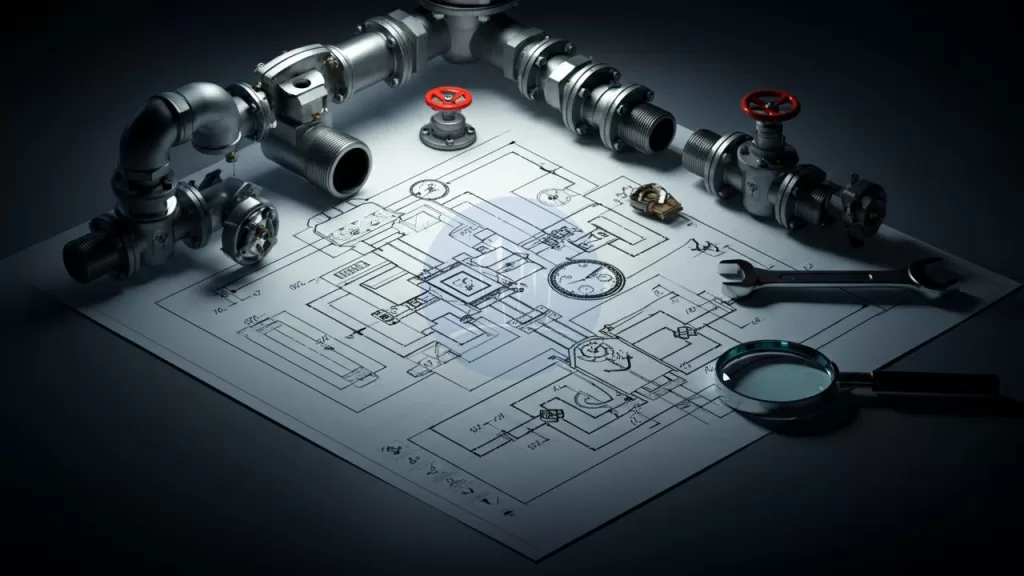
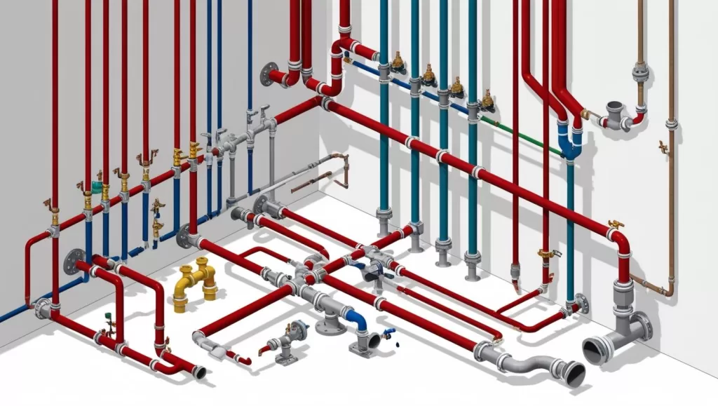
Piping isometric drawings are essential tools in the engineering and construction of pipeline systems. They provide a three-dimensional representation of pipelines in a two-dimensional format, helping engineers visualize complex layouts. Unlike other drawing styles, piping isometric drawings depict the height, width, and depth of the pipeline. This depiction allows for precise planning and communication among project teams. These drawings are critical for pipeline fabrication and ensure that installations align with design specifications.

In this article, we will explore piping isometric drawing symbols. We will also cover isometric pipe drawing symbols and how to read isometric piping drawings. Understanding these symbols and techniques is crucial for accurate and effective pipeline design and construction.

  1. Key Components of Piping Isometric Drawings
  2. Importance of Isometric View in Piping
  3. Piping Isometric Drawing Symbols
  4. How to Read Piping Isometric Drawings
    1. Representation of pipe fittings drawings
    2. Representation of pipe fittings and pipe materials
  5. Representation of pipe fittings in piping isometric drawings
    1. Valve Symbols
    2. Flanges symbols
    3. Instrument Symbols
  6. Applications of Isometric Drawings in Piping Systems
  7. Annotations and Labels in Piping Layout Drawings
  8. Color Code in Piping Systems
  9. Applications of Isometric Drawings in Piping Systems
  10. Steps to Create Isometric Drawings for Piping
  11. Common Challenges in Isometric Piping Drawings
  12. Comparison of Isometric and Orthographic Drawings
  13. Piping Isometric Drawing Standards and Guidelines
  14. Three Main Rules in Isometric Drawing
    1. Key Takeaways: Piping Isometric Drawings and Symbols
  15. Conclusion

Key Components of Piping Isometric Drawings

Piping isometric drawings are crucial in pipeline design, providing 3D representations in a 2D format. They simplify complex layouts, enhance visualization, and ensure accurate fabrication with standardized symbols and clear details.

Piping isometric drawing symbols

Key features of isometric drawings for piping include:

  • A 30-degree angle projection for all axes to show depth.
  • Use of Standardized Symbols: Incorporates symbols for pipes, valves, elbows, and fittings, ensuring consistency and ease of understanding.
  • Precise Dimensions: Includes detailed measurements and angles, aiding accurate fabrication and assembly.
  • Annotations and Notes: Offers material specifications, pipe sizes, welding instructions, and operational details.
  • Flow Direction Indicators: Utilizes arrows and markings to show the flow direction of fluids within the pipeline.
  • Simplified Layout Interpretation: Easier to read compared to other technical drawings, helping teams visualize complex configurations.
  • Fabrication-Friendly Design: Acts as a guide for manufacturers, reducing errors and material wastage.
  • Compliance: Ensures adherence to design and construction standards, supporting effective project execution.
  • Inclusion of key elements such as piping symbols for isometric drawings, directional arrows, and dimension lines.
    These features make isometric drawings of pipelines a preferred choice for complex projects.

Importance of Isometric View in Piping

The isometric view in piping is a visual representation technique. It shows all three dimensions length, width, and height—at equal scales. This unique perspective simplifies complex pipeline layouts, making it easier for engineers to interpret designs accurately. Isometric views provide a clear and comprehensive depiction of the pipeline geometry. This clarity allows engineers to identify potential design challenges or conflicts before construction begins. This visualization method enhances communication among project teams. It ensures that intricate systems are easier to comprehend. This approach ultimately saves time and reduces errors in fabrication and installation processes. The isometric view in piping plays a vital role in streamlining project execution and improving overall design accuracy.

More related posts

Piping Isometric Drawing Symbols

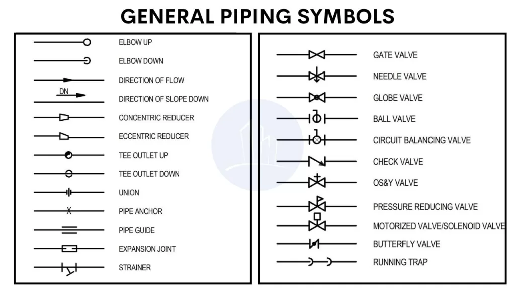
Piping isometric drawing symbols act as a universal language for engineers and fabricators.

Piping isometric drawings represent three-dimensional pipeline systems on a 2D plane. They offer a clear understanding of complex pipe routing across multiple planes. These drawings use single-line representations of pipe centerlines to measure dimensions. They incorporate symbols for components like valves, flanges, reducers, and welds. Common symbols include:

Isometric drawing for piping
  • Valves: Represented by geometric shapes such as circles or rectangles with annotations.
  • Flanges: Depicted as two parallel lines intersecting the pipe.
  • Reducers: Indicated by a tapered line connecting different pipe diameters.
  • Elbows: Shown with angular bends.

How to Read Piping Isometric Drawings

Understanding isometric pipe fittings drawings is crucial when handling complex pipeline systems. These drawings offer a three-dimensional visualization of piping layouts on a two-dimensional surface. They aid engineers, designers, and operators in effective planning and execution. A standard 30-degree angle is applied to the axes, which ensures equal foreshortening of length, width, and height.

This creates a proportional and clear perspective. This approach provides precise information about pipe routes, dimensions, and connection details. It makes it easier to analyze and implement designs. Additionally, it minimizes errors during construction or maintenance. Mastery of isometric pipe fittings drawings enhances efficiency and communication among all stakeholders in pipeline projects.

Representation of pipe fittings drawings

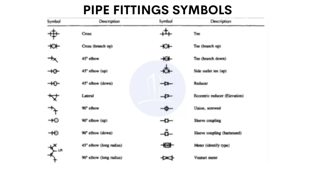
Piping isometric drawings use standardized symbols to represent different pipe fittings and components. These symbols convey critical information about the type, size, and orientation of pipes, valves, and other equipment. Recognizing these symbols is essential for accurately interpreting the layout and functionality of the piping system depicted in the drawing.

Piping isometric drawing symbols

Representation of pipe fittings and pipe materials

Piping isometric drawings specify the material of the pipes, such as carbon steel, stainless steel, copper, or PVC. This information is crucial for understanding the system’s properties and requirements.

In piping isometric drawings, pipes are represented as single lines to simplify the layout. These lines include key information such as pipe size, material, and specification. Arrows indicate flow direction, while symbols represent fittings, valves, and connections. The drawings maintain a 30-degree angle for clarity and accurate visualization.

Representation of pipe fittings in piping isometric drawings

Each fitting is represented by a unique symbol on the isometric drawing. This allows you to quickly identify the components. You can also see their orientation within the system.

Pipe fittings drawings

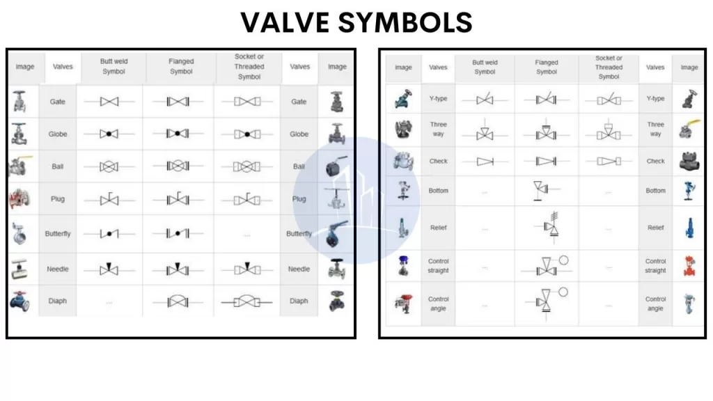
Valve Symbols

Piping isometric drawings use standardized symbols to represent different types of valves, such as ball, gate, and globe valves. These symbols are typically color-coded to distinguish the valve type.

Pipe fittings drawings
Pipe fittings drawings -Valves

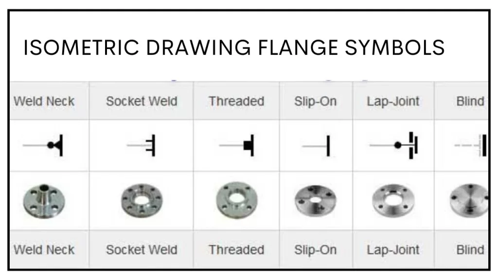
Flanges symbols

Flange symbols in piping isometric drawings represent the connection points between pipes or pipe and equipment. These symbols vary based on flange type.

Flanges
Piping isometric drawing symbols (Flanges)

Instrument Symbols

Instruments like pressure gauges, thermometers, and flow meters are also depicted using standardized symbols in isometric drawings. These help identify the location and type of instrumentation along the piping system.

Instruments symbols
Instruments

Applications of Isometric Drawings in Piping Systems

Piping layout drawings provide critical information essential for designing and constructing pipeline systems. Here’s what can be obtained from them:

  • Pipe Routing: Exact pathways of pipes, including elevations and orientations.
  • Equipment Locations: Placement of machinery and fixtures in relation to the piping system.
  • Material Specifications: Details about pipe materials, insulation, and coatings.
  • Dimensions: Measurements of pipe lengths, offsets, and distances between components.
  • Fittings and Connections: Types of joints, flanges, and fittings required.
  • Support Systems: Locations and types of pipe supports, hangers, and anchors.
  • Flow Direction: Indicated by arrows to ensure proper operation.
  • Valves and Instruments: Placement and specifications of valves, gauges, and control devices.
  • Safety Features: Emergency shut-off systems and pressure-relief valves.
  • Compliance Data: Adherence to standards, codes, and regulations.

This ensures accuracy and efficiency in pipeline installation and maintenance.

Annotations and Labels in Piping Layout Drawings

  • Pipe Size and Material: Specifies the diameter and material (e.g., steel, PVC) for each pipe, ensuring compatibility.
  • Flow Direction: Uses arrows to indicate the direction of fluid or gas flow within the system.
  • Equipment Tags: Labels machinery and equipment with unique identifiers for easy referencing.
  • Elevation Indicators: Highlights the height or depth of pipes, critical for alignment.
  • Connection Details: Annotates welds, flanges, or threaded connections for assembly.
  • Valve Types and Numbers: Identifies valve locations, types (e.g., gate, globe), and tag numbers for functionality.
  • Support Annotations: Labels pipe supports, hangers, or brackets with their specifications.
  • Insulation and Coating: Notes areas requiring thermal insulation or corrosion-resistant coatings.
  • Instrument Tags: Marks sensors, gauges, and monitoring instruments with unique labels.
  • Safety Instructions: Includes warnings, emergency shutoff points, and safety compliance notes.

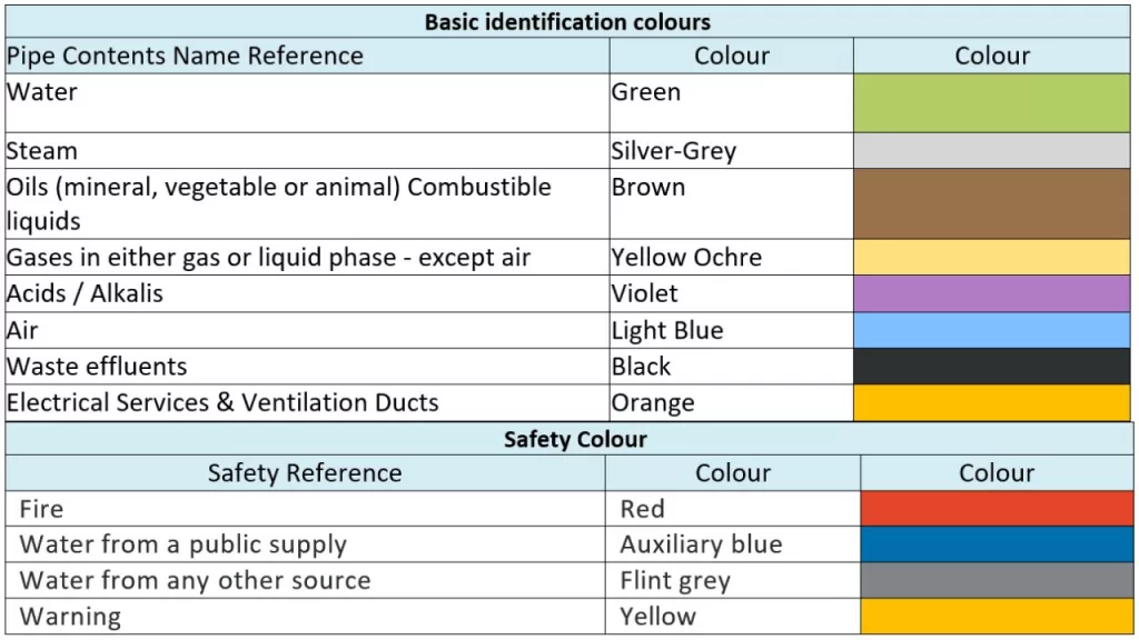
Color Code in Piping Systems

Color coding in piping systems is a standardized method to identify the contents of pipelines for safety and operational efficiency. It aids in quick recognition during maintenance and emergencies.

Piping isometric drawing color codes
color codes
  • Fluid Type Identification: Different colors represent various fluids like water, steam, oil, or gases.
  • Hazard Awareness: Highlights dangerous contents, such as flammable or toxic substances.
  • Directional Arrows: Used alongside color codes to indicate the flow direction.
  • Compliance Standards: Adheres to codes like ANSI/ASME A13.1 or ISO standards for global consistency.
  • Maintenance Assistance: Simplifies troubleshooting by providing instant recognition of pipeline contents and purpose.

A well-read piping isometric drawing minimizes errors in pipeline fabrication and installation.

Applications of Isometric Drawings in Piping Systems

Isometric drawings are vital for designing, installing, and maintaining piping systems, providing comprehensive details about dimensions, layout, and materials in a three-dimensional perspective.

Applications

  1. Design Visualization: Offers a clear 3D view of piping layouts, simplifying complex designs.
  2. Fabrication Guidance: Specifies pipe lengths, angles, and fittings, aiding precise fabrication.
  3. Installation: Guides field teams on accurate pipe placements and alignment.
  4. Material Estimation: Lists materials required for efficient planning and procurement.
  5. Maintenance and Repair: Identifies pipe locations and connections for quick repairs.
  6. Conflict Resolution: Highlights spatial clashes to prevent on-site issues.
  7. Compliance: Ensures designs meet safety and engineering standards.

Steps to Create Isometric Drawings for Piping

Creating isometric drawings for piping involves several key steps to ensure precision. Start by preparing the piping layout, including all components like valves, elbows, tees, and pumps. Set up the isometric grid at the required scale, using a 30-degree angle to represent the three dimensions. Define pipe diameters to mark the size of each pipe accurately. Next, plot the piping components, including pipe runs, fittings, and equipment, using the grid. Add details like material types, flow direction, and any additional specifications. Finally, review and validate the drawing for accuracy, ensuring it aligns with the engineering design.

Various software tools can streamline this process. AutoCAD is great for both 2D and 3D piping designs with isoplane settings. Revit, used in BIM-based designs, generates detailed isometric views and integrates with other data. Tools like SolidWorks, SmartPlant 3D, and MicroStation enhance 3D modeling, offering automation and flexibility for efficient, accurate isometric piping designs.

Common Challenges in Isometric Piping Drawings

Challenges in isometric drawings for pipelines include:

  • Scaling Issues: Misinterpretation of dimensions is common when scaling the drawing. Accurate scaling is crucial to ensure that components fit as designed in the real-world installation.
  • Symbol Miscommunication: Incorrect or inconsistent use of isometric pipe drawing symbols can lead to errors. Adhering to industry standards ensures clarity and prevents confusion during the construction or maintenance stages.
  • Complexity in Detailing: Representing multiple components such as valves, joints, and fittings in a three-dimensional system can be overwhelming, requiring careful attention to maintain accuracy and detail.
  • Alignment and Layout: Improper alignment of pipes and components can disrupt the flow of the design and cause potential installation issues.

Comparison of Isometric and Orthographic Drawings

The Piping isometric drawings and orthographic drawings serve different purposes:

  • Isometric Drawings: Provide a 3D perspective, showing depth, width, and height in a single view, ideal for visualizing complex systems.
  • Orthographic Drawings: Focus on individual planes (top, side, front), giving precise measurements for construction but lacking the 3D perspective.
  • Complex Layouts: Isometric views in piping offer superior clarity and help in understanding the spatial arrangement of components.

Piping Isometric Drawing Standards and Guidelines

International Standards:

  1. ISO 128-30:2017 – This standard outlines the general principles for creating isometric drawings. It includes the use of a 30-degree angle for projections. These projections represent three-dimensional objects on a two-dimensional plane. It ensures uniformity across industries and geographical boundaries.
  2. ASME Y14.5-2009 – The American Society of Mechanical Engineers (ASME) standard provides guidelines on dimensional tolerances, including isometric drawings. It also covers how to represent pipe sizes, materials, and flow directions.
  3. ANSI/ASME B31.3 – This standard for Process Piping explains how isometric drawings should accurately represent the piping system. It includes component layout and material specifications. Additionally, it standardizes symbols for valves, flanges, and fittings.
  4. ISO 5457:2012 – This specifies the size of drawings. It includes the standard sheet size used for isometric drawings. This ensures they are universally recognizable and maintain clarity.

Indian Standards:

  1. IS 696:1972 – The Indian Standard for Engineering Drawing lays the foundation for isometric projections. It also standardizes the use of symbols for different components like valves, elbows, and flanges. It is consistent with international practices in dimensioning and symbol representation.
  2. IS 10701:1983 – This standard applies to the design and drafting of piping systems. It offers specific guidelines for the representation of isometric drawings. It also includes material codes and component alignment.
  3. IS 1235:1982 – This standard focuses on the quality of engineering drawings. It establishes conventions for piping isometric drawings, including scale and symbol usage. These conventions ensure clear communication in the installation and maintenance of piping systems

By adhering to these standards, designers and engineers can create isometric drawings that are clear and standardized. These drawings are easily interpretable across regions and industries.

Three Main Rules in Isometric Drawing

In isometric drawing, three main rules ensure accuracy and clarity:

  1. 30-Degree Angle: The drawing is created using a 30-degree angle to show all three dimensions (length, width, and height) equally foreshortened.
  2. Equal Scaling: All axes should be scaled equally to maintain proportionality and prevent distortion.
  3. Straight Lines: Maintain straight lines for pipes and components, ensuring accurate measurements and preventing confusion.

These rules help in creating precise, easy-to-read representations of three-dimensional systems on a two-dimensional plane.

Key Takeaways: Piping Isometric Drawings and Symbols

  • Essential for Piping: Isometric drawings provide a 3D representation of complex pipeline systems on a 2D plane, showing height, width, and depth for precise planning and communication.
  • Standardized Symbols: These drawings use universally recognized symbols for components like valves, flanges, and fittings, ensuring clarity and consistency in interpretation.
  • Simplified Visualization: The isometric view simplifies complex layouts, aiding engineers and project teams in visualizing and understanding intricate pipeline configurations.
  • Fabrication and Installation Guidance: Precise dimensions, annotations, and material specifications in isometric drawings guide accurate fabrication and installation processes. This reduces errors and ensures compliance with design requirements.
  • Effective Communication: Piping isometric drawings facilitate clear communication among engineers, fabricators, and installers, ensuring accurate execution and minimizing potential conflicts.
  • Standards and Guidelines: Adhering to international and national standards ensures the quality, consistency, and universal interpretability of isometric drawings.

Conclusion

Piping isometric drawings play a critical role in the design, installation, and maintenance of piping systems. Their 3D representation ensures clarity, making complex piping layouts easier to understand and execute. By incorporating standardized symbols for fittings, flanges, and instrumentation, these drawings effectively communicate critical design details. Understanding annotations, color codes, and material representations further enhances their utility. Comparing isometric to orthographic views underscores the unique advantages of each in project execution. Adhering to established standards and guidelines enhances the value of isometric drawings. This adherence ensures precision and efficiency in piping projects across industries. Mastery of these drawings empowers engineers and technicians to streamline workflows, minimize errors, and achieve successful project outcomes.


Self-Compacting Concrete: Key Ingredients and Mix Design

Self-Compacting Concrete (SCC) flows effortlessly and fills complex formwork without requiring external vibration, thanks to its advanced mix design. But what is Self Compacting Concrete? It’s a high-performance concrete that uses a blend of cement, aggregates, and superplasticizers to achieve its self-leveling and self-consolidating properties.

The advantages of SCC are significant. Self Compacting Concrete simplifies placement and improves workability. It reduces the need for manual vibration and thereby cuts labor costs and lowers the risk of defects like honeycombing. This makes SCC ideal for intricate and congested structures such as high-rise buildings, bridges, and underground constructions.

The application of Self-Compacting Concrete enhances construction efficiency by ensuring uniform compaction and a high-quality finish. SCC is a game-changer in concrete technology. Self Compacting concrete provides robust solutions for demanding construction scenarios. It also improves overall structural performance and cost-effectiveness. In this article we are will go through the definition , characteristics, advantages , mix design etc of Self compacting concrete (SCC).

  1. Definition and Characteristics of Self-Compacting Concrete (SCC)
  2. Advantages of Self-Compacting Concrete
    1. Improved Workability
    2. Enhanced Durability
    3. Reduced Labor Requirements
    4. Improved Surface Finish
  3. Self Compacting Concrete – Ingredients and Mix design
    1. Aggregates
    2. Cement
    3. Water
    4. Chemical Admixtures
  4. Performance parameters of self-compacting concrete (SCC)
    1. Flowability and Passing Ability of Self Compacted Concrete
    2. Viscosity and Segregation Resistance
  5. Testing Methods and relevant standards for Self-Compacting Concrete
    1. V-Funnel Test
    2. L-Box Test
    3. J -Ring Test
  6. Application Areas of Self-Compacting Concrete
    1. 1. Complex Structures
    2. 2. Thin-walled Structures
    3. 3. Large-scale Projects
    4. 4. Repair and Rehabilitation
  7. Placement and Finishing Techniques of Self Compacting Concrete
  8. Curing and Strength Development of Self Compacting Concrete
    1. Compressive Strength
  9. Durability and Sustainability of Self Compacting Concrete
  10. Environmental Impact and Recycling of Self Compacting Concrete
  11. Quality Control and Assurance
    1. Material Testing
    2. Slump Flow and V-Funnel Tests
    3. Visual Inspection
    4. Strength Testing
  12. Challenges and Limitations
  13. Future Trends and Research
  14. Key Takeaways
  15. Conclusion

Definition and Characteristics of Self-Compacting Concrete (SCC)

Self-Compacting Concrete (SCC) is a high-performance concrete that doesn’t require external vibration for placement. So, what is Self-Compacting Concrete? This type of concrete flows and consolidates under its own weight, effortlessly filling complex forms and tight spaces.

SCC is known for several distinctive properties:

  • High Flowability: It spreads and fills molds and congested areas with ease.
  • Low Viscosity: This allows SCC to flow around obstacles and through narrow openings without segregating.
  • High Passing Ability: It moves smoothly through narrow openings and congested areas.
  • Excellent Cohesiveness: SCC maintains a homogeneous mixture, preventing segregation.
  • Self-Consolidation: It eliminates the need for external vibration, reducing noise and labor during placement.

These characteristics make SCC ideal for various applications. The use of Self-Compacting Concrete improves placement efficiency. It also enhances quality control. These benefits lead to reduced labor costs and greater structural integrity.

Self compacting Concrete
Self Compacting Concrete

Advantages of Self-Compacting Concrete

The main advantages of Self Compacting Concrete are..

Improved Workability

Self-compacting concrete offers superior workability, eliminating the need for vibration. This significantly reduces labor costs and time required for placement, particularly in complex and congested areas.

Enhanced Durability

The homogenous nature of self-compacting concrete results in a denser and more durable structure. Its ability to fill intricate molds and intricate shapes without voids ensures optimal strength and longevity.

Reduced Labor Requirements

Due to its self-consolidating properties, self-compacting concrete requires less manual intervention, reducing labor needs and potential errors. This translates into cost savings and faster construction schedules.

Improved Surface Finish

Self-compacting concrete eliminates the need for vibration, resulting in a smoother and more uniform surface finish. This is particularly beneficial for exposed concrete structures, where aesthetics are crucial.

Self Compacting Concrete – Ingredients and Mix design

The composition of self-compacting concrete (SCC) is carefully tailored to achieve its unique properties. It involves a precise combination of aggregates, cement, water, and chemical admixtures. The key to SCC’s success lies in the optimal proportioning of these ingredients, ensuring a balanced mix that is highly flowable, stable, and resistant to segregation.

Aggregates

SCC utilizes a well-graded aggregate blend, typically consisting of fine and coarse aggregates. Fine aggregates, such as sand, provide cohesion and fill the voids between coarse aggregates, which provide strength and stability. The grading of aggregates plays a crucial role in ensuring a homogeneous mix that flows smoothly without segregating.

Cement

The type and amount of cement used in SCC are crucial for achieving the desired strength and workability. However, high-quality cement is preferred for SCC. It often has a high fineness and low setting time. This ensures rapid strength development and prevents early setting.

Water

The water content is carefully controlled in SCC to achieve the desired slump flow and prevent excessive bleeding. Insufficient water can lead to a stiff mix, while excessive water can lead to segregation and a reduction in strength.

Chemical Admixtures

SCC typically incorporates various chemical admixtures to enhance its properties and ensure proper performance. These admixtures can include superplasticizers to improve flowability. They also reduce water content. Viscosity-modifying agents control the mix’s consistency. Air-entraining agents enhance freeze-thaw resistance.

  • Mineral Admixtures :Different mineral admixtures used in self-compacting concrete (SCC) contribute various properties, thereby enhancing its performance based on specific requirements
  • Ground Granulated Blast Furnace Slag (GGBS):
    Improves the rheological properties, making SCC more flowable and easier to place.
  • Fly Ash:
    Fills internal voids, reducing pores, which enhances the quality and durability of SCC structures.
  • Silica Fumes:
    Increases the mechanical properties, leading to stronger SCC structures with higher resistance.
  • Stone Powder:
    Enhances the powder content, improving the overall mix and cohesiveness of SCC.

Determining the appropriate Mix Design for self compacting concrete requires a detailed process. It involves careful consideration of the project’s specific requirements. These requirements include the target strength, flowability, and durability. The self compacting concrete mix design is typically based on laboratory testing. Simulation ensures that the SCC meets the desired performance criteria. The mix proportions are often adjusted. Variations in the properties of the materials used are considered. Environmental conditions during placement are also taken into account.

Performance parameters of self-compacting concrete (SCC)

Performance parameters of self-compacting concrete (SCC) include flowability and passing ability. Segregation resistance and setting time are also essential. They are crucial for optimal quality and efficiency. Let us go through in detail.

  • Flowability and Passing
  • Viscosity and Segregation Resistance

Flowability and Passing Ability of Self Compacted Concrete

Both are key parameters in evaluating self-compacting concrete (SCC). Flowability refers to the concrete’s ability to flow smoothly under its own weight, filling formwork without segregation. Passing ability measures the concrete’s capacity to move through narrow openings and congested reinforcement without obstruction. These properties ensure that SCC fills the formwork uniformly, creating a dense structure.

Self Compacting Concrete

Factors such as rheological properties, particle size distribution, and admixtures influence both flowability and passing ability. Standardized tests such as the L-box and V-funnel tests assess these qualities. The L-box test measures the concrete’s ability to flow horizontally through a restricted area. The V-funnel test evaluates how quickly the concrete passes through a vertical funnel.

Optimizing these properties ensures a smooth flow, producing a durable, homogenous concrete structure with improved strength and performance.

Viscosity and Segregation Resistance

Viscosity in self-compacting concrete (SCC) is crucial for its flowability and homogeneity during placement. SCC’s high viscosity helps prevent segregation, where heavier aggregates settle, weakening the mixture. Segregation resistance is another key aspect. Segregation resistance means SCC can resist the separation of components. These components include cement paste, aggregates, and water during transport and placement.

Viscosity ensures the mixture stays stable and uniform, resulting in a durable structure. Factors influencing SCC’s viscosity include admixture type and dosage, water-to-cement ratio, aggregate size and shape, and temperature. Proper control of these factors is essential for achieving optimal viscosity and segregation resistance.

Testing methods like the slump flow, V-funnel, and L-box tests assess SCC’s viscosity and segregation resistance. These tests provide critical insights into the concrete’s flow characteristics and suitability for specific applications.

Testing Methods and relevant standards for Self-Compacting Concrete

Testing methods for self-compacting concrete (SCC) ensure that the concrete meets the required performance parameters for flowability, cohesiveness, and stability. Both Indian and international codes provide guidelines for these tests to ensure consistent quality and performance. Here’s an overview of the key testing methods and relevant codes.

Testing methods are crucial for ensuring the quality and performance of self-compacting concrete (SCC). These tests evaluate various properties of SCC, including its flowability, passing ability, viscosity, segregation resistance, and compressive strength.

V-Funnel Test

The most common test for flowability is the V-funnel test. It measures the time it takes for a predetermined amount of concrete to flow through a V-shaped funnel. This test assesses the concrete’s ability to spread easily and fill complex shapes.

Indian Standard: IS 9103: 1999

International Standard: JIS A 1128 (Japan)

V - Funnel Test
V- Funnel Test for SCC

L-Box Test

The L-box test assesses the passing ability of SCC, measuring its capacity to flow through narrow openings and congested areas. This test involves placing the concrete in a box with a horizontal opening. The next step is measuring the time it takes for the concrete to pass through.

Indian Standard: No specific standard; often aligned with international practices.International Standard: EN 12350-10 (Europe)

J -Ring Test

To evaluate the viscosity of SCC, the J-ring test is often employed. In this test, the concrete is placed in a J-shaped ring. The time it takes for a portion of the concrete to settle to the bottom is then measured. This test helps determine the concrete’s resistance to flow and its ability to maintain its shape.

International Standard: EN 12350-12 (Europe)

Finally, the compressive strength test assesses the concrete’s load-bearing capacity. This test involves subjecting a concrete cylinder to a compressive force until it fails. The resulting compressive strength value indicates the concrete’s ability to withstand external pressures.

Testing methods for self-compacting concrete are critical to ensure it performs as expected in various applications. Practitioners should adhere to both Indian and international codes, such as those from IS, ASTM, JIS, and EN. This adherence ensures SCC meets the required standards for flowability, cohesiveness, and structural integrity.

Application Areas of Self-Compacting Concrete

1. Complex Structures

Self-compacting concrete excels in intricate structures with congested reinforcement. It is ideal for columns with dense rebar arrangements. It also works well for precast elements with complex geometries. It can flow and fill the formwork without vibration. This ability significantly reduces the risk of voids and defects. It ensures high-quality concrete in these challenging applications.

2. Thin-walled Structures

Self-compacting concrete is ideal for thin-walled structures, such as precast walls, panels, and beams. It eliminates the need for excessive vibration, which can damage these delicate elements. The concrete’s ability to flow evenly and compact itself ensures uniform thickness and prevents cracking or delamination.

Self Compacting Concrete - Thin Structures
Self Compacting Concrete

3. Large-scale Projects

Large-scale infrastructure projects, such as bridges, dams, and tunnels, benefit greatly from the efficiency and effectiveness of self-compacting concrete. Its high flowability allows for rapid placement, reducing downtime and accelerating construction schedules. Additionally, it minimizes labor requirements, leading to cost savings and enhanced productivity.

4. Repair and Rehabilitation

Self-compacting concrete plays a crucial role in the repair and rehabilitation of existing structures. Its ability to penetrate cracks and fill voids effectively ensures durable and long-lasting repairs. It is especially valuable for restoring concrete structures damaged by wear and tear. Environmental factors or seismic events also cause damage.

Placement and Finishing Techniques of Self Compacting Concrete

Placing and finishing self-compacting concrete (SCC) requires specific techniques due to its unique properties. Unlike conventional concrete, SCC’s high flowability and self-compacting nature necessitate careful handling and finishing methods to achieve optimal results.

The placement of SCC typically involves pumping or conveying the concrete directly into the formwork. This process minimizes segregation and ensures uniform distribution of the concrete mixture. In some cases, placing SCC using a crane or a bucket is also possible. However, it’s crucial to avoid dropping the concrete from a height as this can lead to segregation and air entrainment.

Finishing SCC requires specialized techniques to achieve a smooth and even surface. Due to the concrete’s high flowability, traditional troweling and screeding methods are less effective. Instead, vibrators commonly consolidate the concrete and eliminate air bubbles. Specialized finishing tools, such as vibrating screeds, are also available to achieve a smooth and consistent finish.

  • The use of vibrating screeds helps to compact the concrete. It removes air voids, leading to a smooth and even surface finish.
  • In some cases, achieving the desired surface finish may require a combination of hand finishing techniques. These can include methods such as troweling or floating.
  • It’s important to ensure proper compaction of the concrete during placement. Consolidate it properly during finishing to prevent cracking and other defects.

Curing and Strength Development of Self Compacting Concrete

Curing is a vital step in the life cycle of self-compacting concrete (SCC). It significantly impacts its strength development. It also affects its long-term performance. It ensures that moisture and temperature are maintained, promoting the hydration process that binds the concrete. SCC usually needs at least 7 days to develop initial strength. Longer periods are recommended for optimal strength and durability.

Curing of self Compacting Concrete

Different curing methods are available for use. These include water curing, plastic sheets, curing compounds, and steam curing. The choice depends on project needs and environmental conditions. Factors such as cement type, water-cement ratio, aggregate size, and curing conditions influence SCC’s strength. Generally, higher cement content and lower water-cement ratios lead to greater strength. Admixtures like superplasticizers and silica fume can significantly improve strength development. They ensure better performance and durability of the concrete structure.

Compressive Strength

Compressive strength is essential for evaluating concrete performance. It is measured in units of pounds per square inch (psi) or megapascals (MPa). SCC normally reaches compressive strengths from 3,000 to 8,000 psi (20 to 55 MPa). These levels can go higher, depending on the mix design and curing conditions. The compressive strength of SCC is determined by standardized testing methods, such as ASTM C39 or EN 12390-4.

Durability and Sustainability of Self Compacting Concrete

Self-compacting concrete (SCC) offers significant advantages in terms of durability. It also enhances sustainability. This contributes to the longevity and environmental friendliness of structures. Its inherent properties promote long-term performance and minimize environmental impact.

  • SCC’s excellent workability and compaction ensure a dense and homogeneous concrete matrix, reducing the occurrence of voids and micro-cracks. This improves the concrete’s resistance to permeability. It also prevents the ingress of harmful substances like chlorides and sulfates. These substances can lead to deterioration over time.
  • The use of high-quality aggregates improves SCC resistance to abrasion. Optimized mixture proportions also enhance its resistance to freeze-thaw cycles and chemical attack. These characteristics are crucial for structures exposed to harsh environments, such as coastal areas or industrial sites.
  • The reduced use of water in SCC mixtures compared to conventional concrete minimizes the potential for shrinkage cracking. This contributes to the overall structural integrity and durability of the concrete.
  • SCC’s excellent flowability allows it to fill intricate formwork and complex geometries, reducing the need for vibration and manual compaction. This minimizes noise and vibration pollution during construction, enhancing sustainability and reducing the carbon footprint.

By promoting durability and sustainability, SCC contributes to the longevity of structures. It also enhances the environmental friendliness of structures. These factors make it a preferred choice for various applications in modern construction.

Environmental Impact and Recycling of Self Compacting Concrete

Self-compacting concrete (SCC) offers several environmental benefits compared to traditional concrete. It eliminates the need for vibration, reducing noise pollution and fuel consumption during construction. Its enhanced workability minimizes waste and lowers the volume of concrete needed, cutting carbon emissions from production and transportation.

SCC’s environmental impact is further reduced by its recyclability. Aggregates and cement can be reclaimed and reused, lessening the need for virgin materials. SCC’s high flowability allows for the use of recycled aggregates, supporting sustainable construction practices.

To further reduce SCC’s environmental footprint, sustainable production methods should be employed. These methods include using recycled materials, optimizing cement content, and adopting low-carbon cement alternatives. Efficient production and transportation processes also help decrease emissions, promoting a more eco-friendly construction sector.

Quality Control and Assurance

Material Testing

Ensuring the quality of concrete materials is crucial for the performance and longevity of self-compacting concrete structures. This involves thorough testing of aggregates, cement, admixtures, and water to ensure they meet the specified requirements. Standardized tests are employed to determine properties like compressive strength, water absorption, and particle size distribution.

Slump Flow and V-Funnel Tests

Flowability and segregation resistance of SCC are assessed using tests like the slump flow test and the V-funnel test. These tests evaluate the concrete’s ability to flow evenly and resist segregation during placement. They provide valuable insights into the mix design and help ensure that the concrete achieves the desired consistency and performance.

Visual Inspection

Visual inspection plays a vital role in quality control for SCC. Experienced personnel assess the concrete mix during batching, mixing, and placement to detect any anomalies. They look for signs of segregation, bleeding, air entrainment, and other irregularities that may indicate quality issues.

Strength Testing

Compressive strength testing of cured concrete specimens is conducted to ensure that the concrete meets the specified strength requirements. This involves breaking standard cylinders or cubes under controlled conditions and measuring the load at failure.

Challenges and Limitations

While self-compacting concrete (SCC) offers many benefits, it also presents challenges. Achieving the right balance between flowability, viscosity, and segregation resistance is crucial. SCC needs to flow easily into complex formwork without segregating. At the same time, it must maintain enough viscosity to prevent excessive bleeding or slump loss. This balance often requires careful mix design adjustments and the use of specialized admixtures.

Consistent quality control is another challenge. Slight variations in mix proportions can affect performance, so strict material handling and mixing are essential. Accurate testing methods are also necessary to monitor flowability and viscosity.

The cost of SCC is generally higher than conventional concrete. This is due to specialized materials and admixtures. These factors can be a barrier for budget-conscious projects. Additionally, skilled labor is required for proper handling and placement.

In certain cases, SCC’s high water content may lead to longer curing times. Its performance can be affected by temperature variations during production and placement.

The field of self-compacting concrete (SCC) is continually evolving. This evolution is driven by a growing demand for high-performance, sustainable, and efficient construction solutions. Research and development efforts are focused on addressing the challenges and limitations of SCC, exploring new materials, technologies, and applications.

  • Enhanced Performance: Research is underway to develop SCC mixes with improved mechanical properties. These properties include higher strength, durability, and resistance to fatigue and cracking. This involves investigating novel admixtures, aggregates, and cementitious materials.
  • Sustainability and Environmental Impact: Efforts aim to reduce the carbon footprint of SCC. This is achieved by incorporating recycled materials, developing low-energy production processes, and exploring the use of sustainable admixtures.
  • Smart Concrete Technologies: The integration of sensors and monitoring systems into SCC is a promising area of research. Smart SCC can provide real-time data on its properties and performance, enabling proactive maintenance and optimization.
  • 3D Printing and Additive Manufacturing: SCC is well-suited for 3D printing applications. It allows for the creation of complex and customized structures. This technology is being explored for both traditional and innovative construction applications.
  • Advanced Simulation and Modeling: Computational modeling and simulation tools are playing an increasingly important role in SCC research. They enable the prediction and optimization of its behavior and performance.

These research trends aim to unlock the full potential of SCC. They strive to make it a more versatile, efficient, and sustainable construction material for the future.

Key Takeaways

  • Definition and Characteristics: Self-Compacting Concrete (SCC) is high-performance concrete that flows and consolidates under its own weight without external vibration. It features high flowability, low viscosity, excellent passing ability, and self-consolidation.
  • Advantages: SCC improves workability, reduces labor requirements, enhances durability, and provides a superior surface finish.
  • Ingredients: SCC is made from well-graded aggregates and high-quality cement. It also includes controlled water content and various chemical admixtures. These admixtures include superplasticizers and viscosity-modifying agents.
  • Testing Methods: Flowability, passing ability, viscosity, and segregation resistance are assessed using the V-funnel, L-box, and J-ring tests.
  • Applications: Ideal for complex, thin-walled, and large-scale structures, as well as repair and rehabilitation projects.

Conclusion

Self-Compacting Concrete (SCC) represents a significant advancement in concrete technology. It offers numerous benefits such as improved workability, reduced labor, and enhanced durability. Its unique properties, including high flowability and excellent passing ability, make it well-suited for complex and high-demand construction projects. SCC can fill intricate molds effectively. It ensures a uniform finish while minimizing labor and defects. This ability is transformative for the construction industry. Construction professionals can understand SCC’s ingredients, performance parameters, and testing methods. With this knowledge, they can leverage SCC to achieve superior structural performance and efficiency. Embracing SCC can lead to more sustainable, cost-effective, and high-quality concrete solutions in modern construction practices.

Understanding the Concrete Compressive Strength Formula

The  concrete compressive strength formula is fundamental. It calculates how well concrete can resist axial loads without failing. Concrete compressive strength formula is crucial for determining the strength of concrete structures. It also ensures the durability of buildings, bridges, and roads. The formula for concrete compressive strength is expressed as fc = P/A. Here, P is the applied load. A is the cross-sectional area of the concrete specimen. To ensure accuracy, concrete compressive strength testing methods follow strict guidelines.

These guidelines are provided by codes such as ASTM C39 and IS 456. Concrete compressive strength test procedures focus on assessing strength using concrete cubes or cylindrical specimens. These procedures include detailed acceptance criteria to verify whether the concrete meets the required standards. Additionally, a concrete compressive strength data set can help in evaluating the strength over different curing periods. The standard deviation for concrete compressive strength helps assess consistency and quality.

This article is about the concrete compressive strength formula, concrete compressive strength test IS code etc. This also covers concrete compressive strength acceptance criteria,concrete compressive strength testing methods, standard deviation for concrete compressive strength etc.

Table of contents

Introduction to Concrete Compressive Strength Formula

Concrete Compressive strength testing

The concrete compressive strength formula allows engineers to calculate the ability of concrete to withstand compressive forces. Engineers measure Concrete compressive strength in megapascals (MPa) or Newtons per square millimeter (N/mm²). To determine this strength, engineers apply a compressive force to concrete specimens, such as cubes or cylinders, until the concrete fails. The formula for calculating the compressive strength is

f= P/A

Where:

  • fc = Compressive strength (in MPa or N/mm²)
  • P = Maximum applied load (in Newtons)
  • A = Cross-sectional area of the specimen (in mm² or cm²)

Engineers worldwide use the concrete compressive strength formula to confirm that concrete can withstand the necessary loads in construction projects.

Code Requirements – Concrete compressive strength

In the construction industry, the concrete compressive strength formula is governed by specific building codes. These codes outline the requirements for testing of concrete, the selection of appropriate materials, and the acceptance criteria for compressive strength. ASTM C39 is the Standard Test Method for Compressive Strength of Cylindrical Concrete Specimens. IS 456:2000 is the Indian Standard for Code of Practice for Plain and Reinforced Concrete. These standards define the procedures. They also set the acceptable limits for concrete compressive strength.

Adhering to these codes ensures that concrete meets the structural requirements, offering durability and safety in construction. Codes provide specific guidelines on concrete compressive strength testing methods, detailing the use of cubes or cylinders and specifying curing times before testing.

concrete compressive strength
concrete compressive strength testing

Concrete Compressive Strength Test Methods

Testing for concrete compressive strength is a crucial step in the quality control process. Several methods exist, but the most common involves casting concrete specimens (usually cubes or cylinders) and subjecting them to a compressive load. The concrete compressive strength test is typically conducted according to specific standards and includes the following steps:

  • Sample Preparation: Technicians pour concrete into molds and allow it to cure for a specified period, often 7, 14, or 28 days.
  • Testing: They place the cured specimen in a testing machine that gradually applies force until the specimen fails. They then record the maximum load.
  • Calculation: Using the  concrete compressive strength formula, they apply the maximum load and cross-sectional area to determine the concrete’s strength.

For cylindrical specimens, the compressive strength of cylindrical concrete specimens formula

Concrete compressive strength formula

Where A is the cross-sectional area of the cylinder (in mm² or cm²). The load is applied along the axis of the cylinder.

Concrete Compressive Strength Data Set

Engineers compile data sets from past concrete test results under various conditions to evaluate the reliability of concrete’s compressive strength. These data sets include information on specimens tested with different curing times, temperatures, and mix compositions, allowing engineers to assess consistency and predict performance trends. These conditions include curing time, aggregate type, water-cement ratio, and  cement grade. The data helps engineers make informed decisions about the mix design and predict the likely compressive strength of new batches of concrete.

Compressive Strength of Concrete Cube Formula

The compressive strength of concrete cube formula is similar to that of cylinders. In this case, a concrete cube of standard size (typically 150 mm x 150 mm x 150 mm) is tested. The formula remains

Compressive strength of concrete formula

Where P is the applied load, and A is the cross-sectional area of the cube. Cube specimens are used primarily because they are easier to handle and store than cylinders. Their failure pattern is often easier to interpret.

Standard Deviation for Concrete Compressive Strength

When working with concrete, it is important to measure the compressive strength. It is also crucial to evaluate the variability in strength across different batches. Standard deviation is used to assess this variability. A higher standard deviation indicates that the concrete is more inconsistent, which could lead to structural weaknesses. Engineers aim for a low standard deviation to ensure that concrete consistently meets the required strength standards.

concrete compressive strength
concrete compressive strength -cube testing machine

The formula for calculating standard deviation for concrete compressive strength is:

Standard Deviation Formula

Where σ is the standard deviation.

n is the number of test samples, xi​ is the individual strength value, and x is the mean strength.

Acceptance Criteria

The concrete compressive strength acceptance criteria help in determining if a concrete batch meets the necessary strength. This ensures it is suitable for a given application. These criteria are defined by codes such as ASTM C39 or IS 456 and typically include:

  • Minimum required compressive strength at 28 days (typically expressed in MPa).
  • The number of tests needed to assess the batch.
  • The allowable variation in strength between samples (standard deviation).

If concrete does not meet the acceptance criteria, engineers may reject it or conduct further testing to determine its suitability for use.

Compressive Strength of Concrete: Factors Affecting the Formula

Several factors can influence the concrete compressive strength formula:

  • Water-Cement Ratio: Lower water-to-cement ratios generally result in stronger concrete.
  • Aggregate Size and Type: The choice of aggregates affects the strength of the mix.
  • Curing ConditionsProper curing ensures that hydration continues and the concrete reaches its maximum potential strength.
  • Mix Proportions: The specific proportions of cement, water, and aggregates used in the mix design will affect the compressive strength.

Conclusion

The concrete compressive strength formula is a fundamental tool for engineers. It ensures the structural integrity of  concrete in construction projects. Engineers follow industry standards and testing methods. They also consider factors such as water-cement ratio and aggregate type. This way, engineers can produce reliable and strong concrete that meets the required safety criteria. Understanding different testing methods is essential. Knowing the concrete compressive strength acceptance criteria is also vital for quality control in the construction industry.

By applying the principles outlined in codes, engineers use comprehensive concrete compressive strength data sets. They can guarantee that concrete will perform as expected under various load conditions. This provides safety and durability in all structures.

Key Takeaways

  1. Testing Methods: Engineers measure concrete strength by testing concrete cubes or cylindrical specimens at various curing periods, typically at 7, 14, or 28 days.
  2. Factors Affecting Strength: Factors such as water-cement ratio, aggregate size, mix design, and curing conditions influence concrete compressive strength.
  3. Acceptance Criteria: The concrete must meet specific strength requirements set by relevant codes. Engineers may reject non-conforming concrete or subject it to additional testing to verify its suitability.
  4. Standard Deviation: Standard deviation is used to assess the variability in compressive strength. A lower deviation indicates more consistent concrete strength, which is vital for ensuring safety.
By understanding the concrete compressive strength formula, engineers can ensure concrete’s reliability. They also consider associated factors to enhance safety and performance in various structural applications.