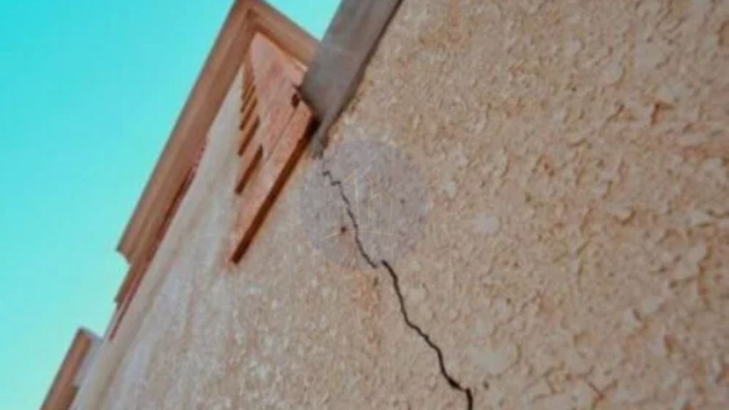
Types of Cracks in Building vary widely, each indicating different causes and requiring specific prevention methods. Common cracks include hairline cracks, which are fine and mostly cosmetic. Shrinkage cracks are caused by concrete drying. Settlement cracks arise from uneven foundation movement. Structural cracks in buildings include horizontal, vertical, diagonal, and shear cracks. These can signal serious foundation or load-bearing issues. Major causes are foundation settlement, thermal movement, chemical reactions, poor workmanship, and soil movement. Understanding these crack types helps in early detection and timely repair, ensuring building safety and durability. Preventive measures like proper soil preparation, use of control joints, quality materials, and regular maintenance are essential to minimize cracking and structural damage.
This comprehensive approach leverages key terms such as crack prevention, repair methods, and building cracks to address common challenges effectively. This article discusses 14 types of building cracks. It explains their causes, such as foundation settlement and thermal movement. It also outlines effective prevention and repair methods to maintain structural integrity. These measures ensure long-lasting building safety.
- Main causes of different types of cracks in building
- Thermal Movement
- Chemical Reaction
- Shrinkage
- Building cracks types generated due to quantity of Cement
- Earthquake
- Vegetation
- Bad construction practices cause some types of cracks in building
- Corrosion Cracks
- Types of cracks in building due to elastic deformation
- Foundation movement and settlement of soil
- Permeability of concrete
- Poor Workmanship
- Lack Of Maintenance
- Types of cracks due to structural design
- Key Takeaways
- Conclusion
Main causes of different types of cracks in building
Cracks in buildings can indicate underlying issues affecting structural stability and safety. Understanding the main causes of different crack types helps in identifying proper repair and prevention strategies. Building cracks commonly result from natural forces, material behaviors, and construction practices that induce stress and movement in structures.
The main causes of different types of cracks in buildings is as follows.
- Thermal Movement
- Chemical Reaction
- Shrinkage
- Types of cracks generated due to cement quantity
- Earthquake cracks
- Vegetation
- Building crack types due to bad construction practices
- Corrosion cracks
- Types of cracks in building due to elastic deformation
- Foundation movement and settlement of soil
- Permeability of concrete
- Poor workmanship
- Lack of maintenance
- Type of cracks due to structural design failures
Related posts from vincivilworld


Thermal Movement
Thermal movement is a common reason for cracks in buildings. It results from the expansion and contraction of materials. These changes are caused by temperature variations. This type of movement occurs irrespective of the structure’s cross-sectional area. All parts of the structure are affected by temperature fluctuations. Thermal stresses develop when materials expand upon heating. They also develop when materials contract upon cooling. This can induce tensile or shear stresses, leading to cracks. These cracks typically appear near points of restraint. These include joint lines, window heads, or structural columns. Movement is hindered at these points.
Preventive Measures for thermal movement
Joints need to be built like construction joints, expansion joints, control joints and slip joints.
Chemical Reaction
- There are chances of chemical reactions to occur because of the materials used to build the concrete or materials.
- Cracks might develop in concrete periodically. This occurs due to expansive reactions developing between aggregate with active silica and alkalis. These alkalis come from cement hydration, admixtures, or external sources.
Preventive Measures for the types of cracks in building
If sulphate content in soil is greater than 0.2 percent or in ground water exceed 300 ppm, leverage very dense concrete and either increase richness of mix to 1:1/5:3.
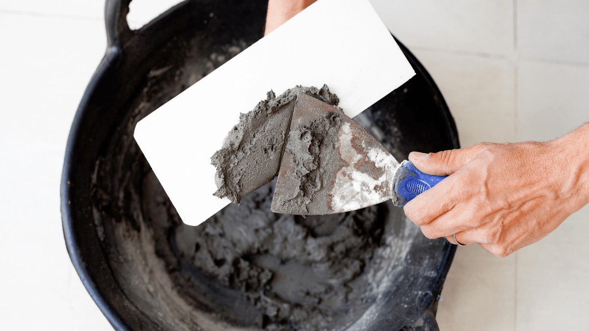
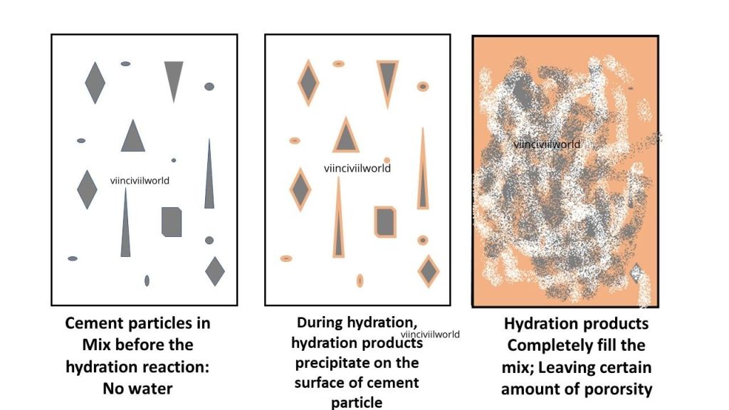
Shrinkage
Most building materials, especially cementitious ones, absorb moisture from the atmosphere and expand, then shrink upon drying. Excessive water in the mortar or concrete mix leads to shrinkage cracks. These are further worsened by the heat of cement hydration. Poor curing practices also aggravate these cracks. These cracks are often hairline. They occur shortly after construction. As the water evaporates from the mix, it causes volume reduction and tensile stresses.
Preventive Measures
Use minimum quantity of water for mixing cement concrete or cements mortar according to water to cement ratio .
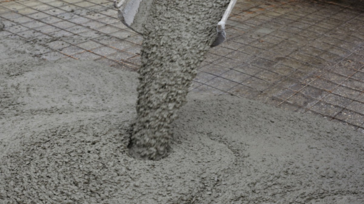
Building cracks types generated due to quantity of Cement
The proportion should be such that the cement in the mix is optimum. Higher the cement, greater the shrinkage/drying.
Preventive Measures
Do not use excessive cement in the mortar mix.
Earthquake
Crack happens because of the rapid shift in lower layer of the earth.
Preventive Measures
Build the foundation of building on firm ground. Tie up the building at base level, door level and roof level with connecting beams.
We covered the first five types of cracks in building. Good to have you here. Let’s move on to the remaining.
Vegetation
- Due to the expansive action of root growing under the base, fast growing trees may often cause cracks in walls in the area around the walls.
- Also, due to moisture contained by roots, cracks occur in clay soil.
Also read: Concept of green building- 4 comprehensive concepts easy read!
Preventive Measures for the types of cracks in building
Do not plant trees too close to the house. If they start growing in or near walls, remove any saplings from the trees as quickly as possible.
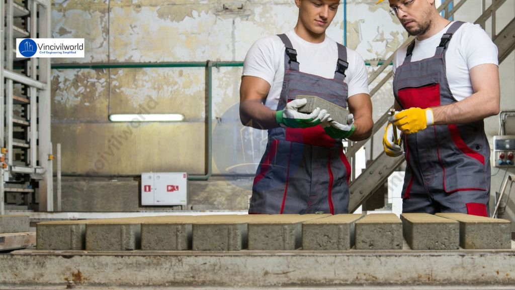
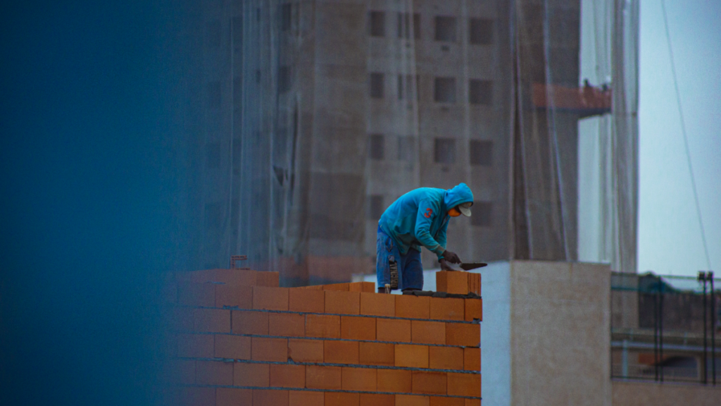
Bad construction practices cause some types of cracks in building
- Owing to indifference, carelessness, greed or incompetence, there is a general lack of good building practices
- It is certainly vital for the building agency and the owner to ensure high quality material selection and good construction practices for a safe building.
Preventive measures
At the time of construction, careful inspection and use of materials of high quality is required.
Corrosion Cracks
- The pH level of the concrete under normal conditions is high (above 12.5).
- The high concrete pH allows for the formation of an inactive layer of ferric oxide around the reinforcement, avoiding corrosion.
- The reinforced steel has two important causes of corrosion: chloride penetration and carbonation.
- Penetration of chloride decreases the concrete’s pH level as oxygen, chlorides, and moisture both enter the concrete.
Preventive measure
As per IS 456-2000, use acceptable covers. When mixing concrete, use potable water.
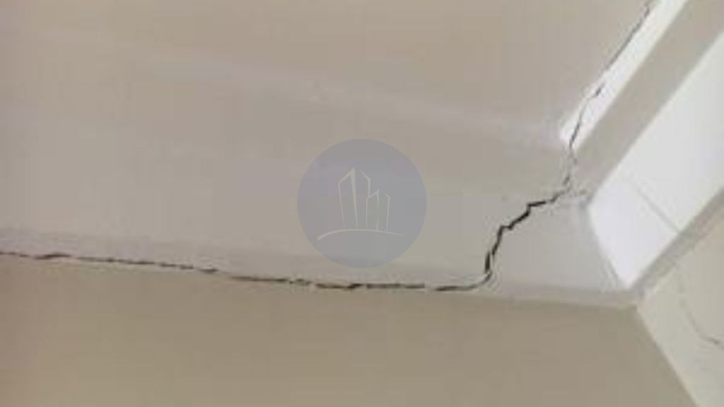
Types of cracks in building due to elastic deformation
- In different sections, unevenly loaded walls experience enormous variations in stress that cause cracks in walls.
- Different shear stresses in these materials result in cracks at the junction when two building materials like masonry, concrete, steel, etc.
- with broadly different elastic properties are constructed together under the impact of load.
- In a building’s structural elements, dead and living loads cause elastic deformation.
- The amount of deformation depends significantly on the material’s elastic modulus, the loading magnitude and the component dimensions.
Foundation movement and settlement of soil
- Shear cracks occur in the base due to enormous differential settlement. Structures built on expansive soils that are susceptible to swelling due to changes in soil moisture content are highly susceptible to cracking when absorbing moisture and shrinking when drying.
Permeability of concrete
- The process of corrosion in concrete begins with the penetration of many aggressive agents and is a significant cause of wall cracks.
- Essentially, the ability of concrete to withstand weathering action, chemical attack or some other degradation mechanism is dictated.
- Low permeability is thus the primary factor in concrete resilience.
- Concrete permeability, water-cement ratio, curing, air voids due to poor compaction, use of admixtures, micro-cracks due to loading, cyclic exposure to thermal variations, and concrete ageing are influenced by several factors.
- Cement mixture permeability is a feature of the water-cement ratio due to high-quality materials, sufficient proportioning, and good construction practice.
- Concrete permeability is a direct result of the interconnection and porosity of the cement paste pores.
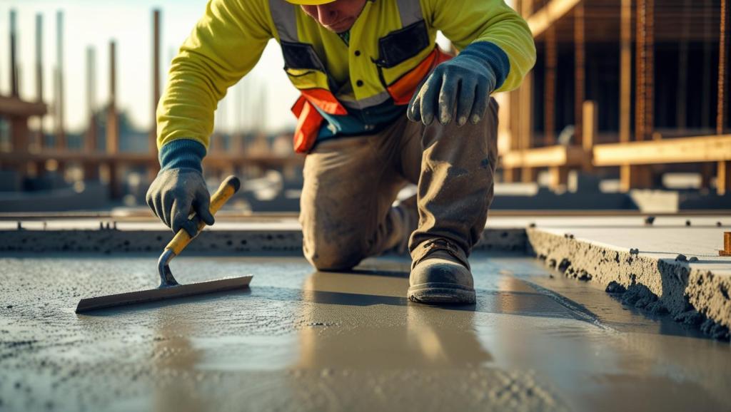
Poor Workmanship
- The lower mixing of building materials such as sand, cement and concrete, creates cracks on walls, slabs, beams, etc.
- Bad workmanship typically results from a lack of proper oversight, incompetence, neglect, and many others, or a mixture of all of these.
Lack Of Maintenance
- It is necessary to take good care of your home at all times, and this can be achieved by doing routine maintenance work.
- This means the foundation of the building remains intact and it also contributes to its lifetime.
Time to meet the last cause. Its the structural design of the structure.
Types of cracks due to structural design
- Poor or bad structural design and specifications are another striking causes of the cracks in buildings made of majorly concrete.
- The designer needs to consider all the environmental aspects which include soil investigations, this will enable the designer to come up with a properly robust design of the foundation.
In nutshell, each type of cracks have to be analysed and proper treatment methods and retrofits have to be adopted to restore the structure to last long.
Key Takeaways
- Types of cracks in buildings include hairline, shrinkage, settlement, horizontal, vertical, diagonal, and shear cracks, each indicating specific structural or material issues.
- Major causes are foundation settlement, thermal movement, chemical reactions, poor workmanship, soil movement, and bad construction practices.
- Thermal movement causes cracks due to expansion and contraction of materials under temperature changes; chemical reactions like alkali-silica cause internal pressure cracking.
- Shrinkage cracks arise from drying of concrete, excess water in mix, and poor curing.
- Excess cement in mixtures increases drying shrinkage leading to cracks.
- Earthquakes cause rapid ground shifts producing wide cracks from dynamic loads.
- Vegetation roots exert pressure disrupting soil and foundations, causing cracks.
- Poor workmanship such as improper mixing, low-quality materials, and negligent construction leads to cracking.
- Corrosion from chloride penetration and carbonation lowers concrete pH, causing reinforcement deterioration and cracks.
- Foundation movement and soil settlement induce differential stresses resulting in soil and shear cracks.
- Prevention depends on proper foundation design, soil preparation, quality materials, control joints, and routine maintenance.
Conclusion
Understanding the various types of building cracks and their root causes is crucial for ensuring structural safety and durability. Cracks not only diminish a building’s aesthetic value but also can severely impact its integrity if left untreated. Major contributing factors include thermal movements, chemical reactions, soil settlement, poor workmanship, and inadequate structural design. Proper site and foundation preparation can significantly reduce crack formation. The use of expansion and control joints is important. Employing quality building materials also helps. Skilled workmanship is essential. Moreover, routine inspections and timely maintenance help detect early signs of cracking and allow prompt repairs, thereby extending the building’s lifespan. Ultimately, a multidisciplinary approach involving design, construction, and maintenance optimizes crack prevention and sustains long-term building performance and safety.
Hope the article could educate you on the types of cracks in building, the main causes and preventive measures. Let me know if you have any doubts in the comments.
Happy learning!