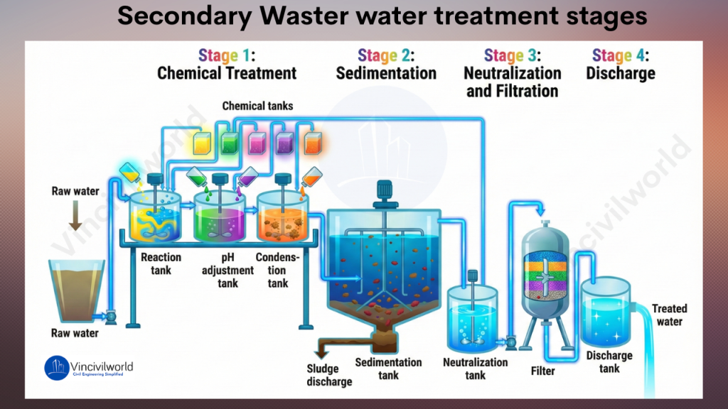
Secondary wastewater treatment uses biological processes to remove dissolved and suspended organic pollutants from sewage. It follows primary treatment and greatly lowers BOD levels. Microorganisms break down waste and improve water quality. This process creates cleaner effluent for discharge or reuse. Secondary treatment of sewage relies on activated sludge systems and trickling filters. These biological wastewater treatment methods work with constant aeration. The wastewater aeration process keeps microorganisms active and effective. Plants use aeration tanks and clarifiers for stable operation. Types of secondary wastewater treatment include activated sludge, oxidation ditches, SBR systems, and trickling filters. Each system supports reliable pollutant removal in municipal and industrial plants. Operators use the secondary treatment process in sewage treatment plants to reduce pathogens and organic matter. Advantages of secondary wastewater treatment include higher efficiency and better environmental protection. Secondary treatment vs tertiary treatment differs by the degree of purification offered.
n this blog, I will walk you through various biological methods used in the secondary treatment of wastewater. Before diving deep into the biological treatment processes, make sure you understand the entire wastewater treatment process. So please go through our blog,
Wastewater Treatment- Stages and Process full details.
- What is Secondary or Biological treatment for wastewater?
- Types of Secondary or Biological wastewater Treatment Methods
- Conclusion
What is Secondary or Biological treatment for wastewater?
Secondary or biological treatment for wastewater uses bacteria to remove dissolved and suspended organic pollutants. These microorganisms consume organic matter as food and convert it into carbon dioxide, water, and energy for growth. This process reduces BOD and improves water quality in the secondary treatment of sewage. It also protects the dissolved oxygen balance in rivers, lakes, and receiving streams. Biological wastewater treatment methods work in controlled environments inside treatment tanks. Operators maintain proper aeration, mixing, and retention time to keep microorganisms active. The wastewater aeration process plays a major role in activated sludge systems and other types of secondary wastewater treatment.
The Biological treatment or decomposition of organic matter takes place in two ways as shown below:
- Anaerobic Wastewater treatment
- Aerobic Wastewater treatment
Anaerobic wastewater treatment works without oxygen and produces biogas. Aerobic wastewater treatment uses oxygen and supports faster decomposition. Both methods enhance the secondary treatment process in sewage treatment plants, and moreover, they ensure efficient pollutant removal.
Anaerobic Wastewater Treatment
Anaerobic wastewater treatment uses anaerobic microorganisms to break down and remove organic pollutants from wastewater. The anaerobic wastewater treatment process consists of two major stages:
- Acidification
- Methane generation
In the initial acid-forming or acidification phase, anaerobes convert complex organic molecules into simpler, short-chain volatile organic acids. The second stage, known as the methane-production phase, includes two key steps:
- Acetogenesis
- Methanogenesis
During acetogenesis, anaerobes transform organic acids into acetate, hydrogen gas, and carbon dioxide. In the methanogenesis step, microbes react with these products to generate methane gas and carbon dioxide, completing the anaerobic treatment process.
Anaerobic systems are widely used for treating wastewater streams with high organic loads and warm temperatures. They offer several advantages over aerobic or biological wastewater treatment methods, including lower sludge production and the generation of valuable energy-rich by-products.
Aerobic Wastewater Treatment
Aerobic wastewater treatment uses oxygen-dependent microorganisms to break down organic pollutants efficiently. Furthermore, this biological treatment process involves aeration tanks where microbes oxidize waste, producing cleaner effluent. As a result, aerobic wastewater systems offer fast decomposition, stable operation, and high treatment efficiency, making them ideal for municipal and industrial aerobic wastewater treatment processes.
The aerobic wastewater treatment systems use oxygen-feeding microorganisms to clean water. These systems take advantage of the natural microbial decomposition process to break down industrial wastewater pollutants and remove them.
Biochemical Oxygen Demand (BOD) is directly related to aerobic wastewater treatment. It measures the amount of oxygen microorganisms need. This oxygen is necessary to break down organic pollutants.
Biochemical Oxygen Demand
The biochemical oxygen demand (BOD) provides a clear measure of the organic pollutants decomposed by bacteria during wastewater treatment. BOD refers to the amount of dissolved oxygen required by aerobic organisms to break down organic matter into smaller molecules. Additionally, high BOD values indicate a greater concentration of biodegradable material in the wastewater, signaling increased organic pollution levels.
Aerobic digestion is preferred for large quantities of dilute wastewater with BOD₅ < 500 mg/L. It is suitable for most aerobic wastewater treatment systems. For highly polluted wastewater streams with BOD₅ > 1000 mg/L, anaerobic digestion is recommended. It handles stronger organic loads more efficiently.
Types of Secondary or Biological wastewater Treatment Methods
The three most commonly used type of aerobic secondary wastewater treatment procedures for are listed below:
- Trickling filter
- Oxidation pond
- Activated sludge wastewater treatment
- Moving Bed Biofilm Reactor (MBBR)
Now, let’s dig deeper into their features and working. Off, we go.
Trickling Filter in Secondary wastewater treatment
A trickling filter is an aerobic secondary wastewater treatment system. It uses a microbial biofilm attached to filter media to break down and remove organic pollutants. This biological wastewater treatment method is called an attached-growth process. In contrast, suspended-growth systems keep microorganisms mixed within the effluent. Trickling filters offer stable performance, effective BOD reduction, and low operational complexity, making them a reliable option in modern secondary wastewater treatment processes.
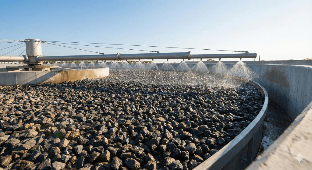
- A trickling filter consists of a fixed bed of rocks, coke, gravel, slag, polyurethane foam, sphagnum peat moss, ceramic, or plastic media.
- As wastewater trickles down, bacteria attach to the media and form a microbial slime layer (biofilm).
- The continuous flow of sewage over the biofilm allows microbes to consume dissolved organic pollutants.
- They release carbon dioxide, water, and other oxidised end products as wastewater passes over the media.
- This process lowers the sewage’s biochemical oxygen demand (BOD).
- Air moving upward through the media crevices supplies oxygen required for aerobic microbial activity.
- The biofilm absorbs and adsorbs organic compounds and inorganic ions such as nitrite and nitrate.
- The biofilm layer needs dissolved oxygen for effective biological oxidation.
- As the biofilm thickens, available oxygen depletes before reaching the lower layers.
- Anaerobic conditions develop at the base of the slime layer.
- Microbes enter a decay stage and lose their ability to attach.
- The biofilm detaches and becomes part of the secondary sludge, a process known as sloughing.
- Trickling filters are widely used in milk processing, paper mills, and pharmaceutical wastewater treatment.
Ever heard of a pond which treats wastewater? Let’s look at what’s happening inside such oxidation ponds.
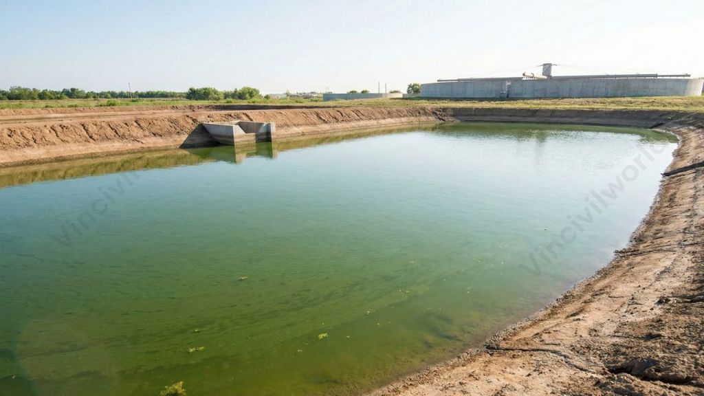
Oxidation Ponds
Oxidation ponds are artificial ponds that treat wastewater through the combined action of sunlight, microbes, and oxygen to reduce organic content and pathogens. Moreover, this waste stabilization pond uses microbes to stabilise residential, commercial, and industrial wastes. Typically, it appears as a shallow treatment pond with a water depth of 2–6 feet.
Industrial or domestic wastewater enters the oxidation pond through the inlet system. Bacteria then convert biodegradable organics into inorganic molecules through microbial interaction, producing carbon dioxide. Common bacteria in these stabilisation ponds include Achromobacter, Proteus, Alcaligenes, Pseudomonas, Thiospirillum, and Rhodothecae.
Anaerobic bacteria first convert insoluble organic waste into soluble organic acids such as ethanol without oxygen. These acids are further decomposed, releasing H₂S, NH₃, CH₄, CO₂, and other gases. Non-biodegradable solids settling at the bottom form sludge.
Most ponds require both bacteria and algae to maximise the breakdown of organic matter and remove contaminants. Algae produce oxygen during photosynthesis and leave an excess amount. Aerobic bacteria use this oxygen for respiration and oxidation of organic matter.
Treated water exits through the pond’s outlet system. Dredging removes accumulated sludge from the pond. Filtration or a combination of chemical treatment and settling removes algal and bacterial biomass.
Now, let’s move on to the various configurations of oxidation ponds.
Oxidation Pond Configurations
Waste stabilization ponds are artificial basins designed for biological wastewater treatment, consisting of single units or multiple series of anaerobic, facultative, or maturation ponds. Moreover, the main oxidation pond configurations used in wastewater treatment are:
- A single facultative pond.
- An anaerobic pond followed by a facultative pond.
- A facultative pond followed by maturation ponds in series.
- A series of maturation ponds preceded by an anaerobic pond and a facultative pond.
These configurations help optimise performance in waste stabilization pond systems.
Anaerobic Pond
Anaerobic ponds are deep ponds (usually 3.0 to 5.0 m) that receive raw wastewater. Most of the solid matter in the wastewater settle to the bottom as sludge. Due to the depth of the pond, oxygen can’t penetrate to the bottom of the pond. Thus the sludge digestion takes place under anaerobic conditions.
Facultative Pond
After coming out of an anaerobic pond, the remaining solid particles in the wastewater settles into a larger but shallow pond called a facultative pond. Air and sunlight kill the harmful germs in the wastewater and makes it less dangerous to the aquatic flora and fauna.
Maturation Ponds
Maturation ponds are two or three ponds in series wherein sunlight and oxygen destroy more harmful germs and make the liquid fit enough to be released for irrigation or into a river. Moreover, the higher the number of maturation ponds, the cleaner the effluent becomes.
Activated Sludge wastewater treatment Process
The Activated Sludge wastewater treatment method employs aerobic microorganisms that can digest organic substances in sewage. Also, they have the ability to cluster together via flocculation. The flocculated particles settle out as sludge. As a result, the liquid coming out is relatively free of suspended solids and organic matter.
The sludge blanket becomes Return Activated Sludge (RAS) once it has settled. Then, the RAS returns to the primary clarifying tanks, where the bacteria in it aid in the breakdown of organic waste in the entering sewage.
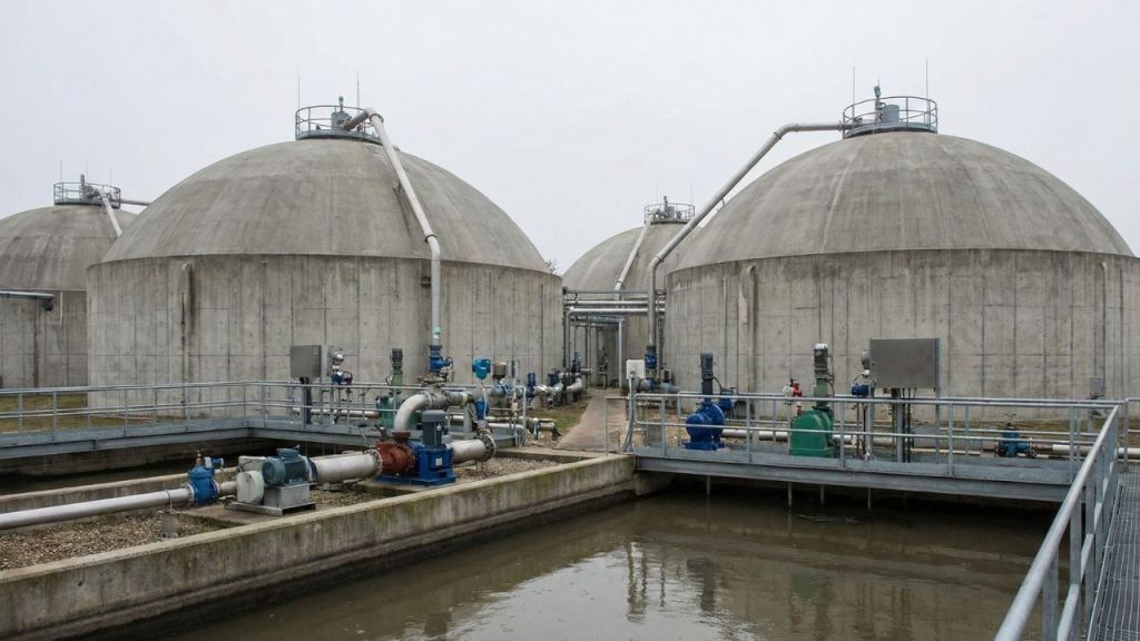
Anaerobic sludge blanket reactors
- A popular method used in the anaerobic secondary treatment for water.
- The wastewater is carried across a free-floating “blanket” of suspended sludge particles in sludge blanket reactors, which are a type of anaerobic treatment.
- Anaerobes in the sludge multiply and accumulate into larger granules that settle to the bottom of the reactor tank and can be recycled for future cycles as they decompose the organic contents in the wastewater.
- The treated effluent rises and exits the unit.
- Throughout the treatment cycle, collection hoods collect biogases produced by the degradation process.
Shall we wrap up?
Key Takeaways
- Secondary wastewater treatment uses biological processes to remove organic pollutants through methods like activated sludge and trickling filters.
- Anaerobic and aerobic treatments both improve water quality, with anaerobic processes operating without oxygen and producing biogas.
- Trickling filters employ a biofilm of microbes on media to reduce biochemical oxygen demand (BOD) and purify wastewater.
- Oxidation ponds rely on sunlight, microbes, and oxygen to treat wastewater, showcasing various configurations for effectiveness.
- Activated sludge processes involve aerobic microorganisms that cluster together, aiding in the removal of suspended solids and organic matter.
Conclusion
We explored the key secondary wastewater treatment methods, including the trickling filter system, oxidation pond process, activated sludge process, and anaerobic sludge blanket reactors. Each of these biological wastewater treatment methods plays a crucial role in reducing organic pollutants, lowering BOD levels, and improving overall effluent quality. The sludge produced from these secondary treatment units undergoes dewatering and digestion to reduce volume and enhance stability. Afterward, the dried sludge is commonly used in landfills or converted into nutrient-rich fertilizer, supporting sustainable wastewater treatment and reuse practices. Ultimately, these methods strengthen modern secondary wastewater treatment systems and ensure reliable environmental protection.
That’s it about secondary treatment methods for wastewater. Hope you found it informative.