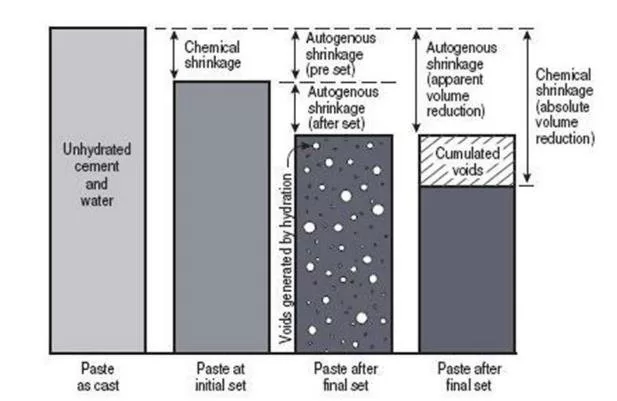
Shrinkage of concrete refers to the reduction in its volume over time, primarily due to moisture loss and chemical reactions during hydration. This phenomenon can lead to shrinkage cracking of concrete, compromising structural integrity and durability. Understanding what shrinkage of concrete is involves recognizing its various forms, such as drying shrinkage, autogenous shrinkage, and thermal shrinkage. Drying shrinkage occurs as moisture evaporates from the hardened concrete. Autogenous shrinkage results from internal chemical reactions during the hydration process. Thermal shrinkage happens due to temperature variations affecting the concrete mass. Factors influencing shrinkage include water-cement ratio, environmental conditions, and the concrete mix design. Mitigating shrinkage involves proper curing practices. It includes using shrinkage-reducing admixtures. Another method is optimizing mix proportions to minimize water content, thereby reducing the potential for shrinkage cracking.
Concrete shrinkage is a critical phenomenon in the construction industry. It refers to the reduction in volume of concrete as it undergoes hydration and drying. This dimensional change can lead to cracking, compromising the structural integrity and durability of concrete structures. Engineers, contractors, and stakeholders must understand the causes, types, and preventive measures of concrete shrinkage. This knowledge ensures the longevity and performance of concrete infrastructures. This article is about the types, causes and effects of Concrete shrinkage
Concrete, a composite material composed of cement,aggregates, water, and admixtures, is the backbone of modern construction. Its versatility, strength, and durability make it the material of choice for various structural applications. However, one inherent characteristic of concrete is its tendency to shrink during the curing process. This shrinkage, if not properly managed, can lead to cracks, reducing the lifespan and safety of structures. Therefore, a comprehensive understanding of concrete shrinkage is paramount for effective construction practices.
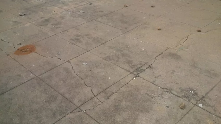
Shrinkage in concrete is the decrease in its volume over time. This occurs due to the loss of moisture and the chemical reactions during cement hydration. This volumetric reduction can induce tensile stresses within the concrete matrix. It leads to the formation of cracks, especially when the material is restrained. Cracks are also likely when shrinkage occurs unevenly. The primary factors influencing concrete shrinkage include the water-cement ratio, environmental conditions, and the properties of the constituent materials.
Types of Concrete Shrinkage
Concrete shrinkage is a natural phenomenon that affects the durability and structural integrity of concrete over time. It occurs due to moisture loss, chemical reactions, or temperature changes, leading to volume reduction and potential cracking. Understanding the different types of shrinkage is crucial. These types include plastic, drying, autogenous, thermal, and carbonation shrinkage. This knowledge helps in selecting appropriate construction techniques. These techniques minimize shrinkage-related issues and improve concrete performance.
Plastic Shrinkage
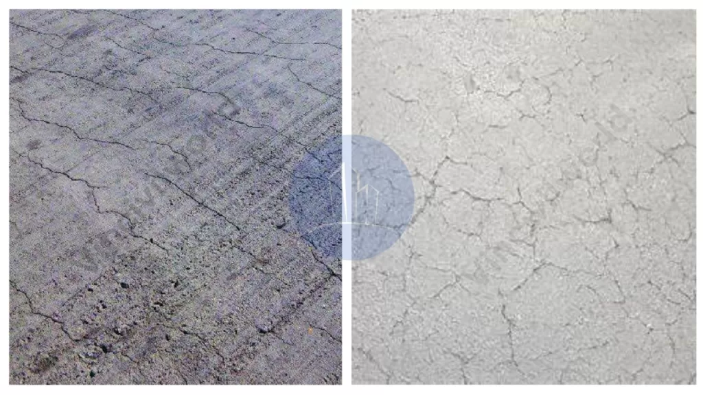
Plastic shrinkage occurs within the first few hours after concrete placement while it is still in a plastic state. It happens due to rapid evaporation of surface moisture, especially in hot, dry, or windy conditions. This leads to surface tension, causing shrinkage cracks to form. These cracks are often random, shallow, and irregular, primarily appearing on slabs and pavements. Preventing plastic shrinkage involves proper curing, windbreaks, shading, and using evaporation retarders to maintain surface moisture and reduce crack formation.
Plastic shrinkage
Drying Shrinkage
Drying shrinkage occurs as hardened concrete loses moisture to the surrounding environment. This process can last months or even years, depending on humidity levels and concrete properties. As water evaporates, capillary tension develops, causing the concrete to contract, leading to shrinkage cracks. These cracks can compromise durability and structural integrity. To reduce drying shrinkage, engineers use shrinkage-reducing admixtures, proper curing methods, and well-graded aggregates. These methods enhance moisture retention and minimize excessive volume reduction.
Autogenous shrinkage is common in high-strength, low water-cement ratio concretes where internal chemical reactions drive volume reduction. Unlike drying shrinkage, it occurs without external moisture loss and results from cement hydration reactions consuming water within the concrete. This type of shrinkage is more pronounced in self-consolidating and high-performance concretes, where fine particles create dense microstructures. To mitigate autogenous shrinkage, internal curing techniques are applied. Techniques such as using lightweight aggregates or superabsorbent polymers help retain water for extended hydration.
Thermal shrinkage is caused by temperature variations during the early curing stages of concrete. Cement hydration generates excess heat, causing the concrete to expand. As it cools, the contraction leads to thermal stress and shrinkage cracks. Large structures, such as bridges and massive foundations, are particularly vulnerable to this effect. To control thermal shrinkage, low-heat cement manages heat dissipation. Temperature-controlled pouring also assists. Insulation methods minimize volume changes, preventing long-term structural issues.
Carbonation Shrinkage
Carbonation shrinkage occurs when carbon dioxide (CO₂) from the atmosphere reacts with calcium hydroxide in concrete to form calcium carbonate. This process slightly reduces concrete volume over time and primarily affects thin concrete sections exposed to high CO₂ levels. Although carbonation can increase surface strength, excessive shrinkage can cause microcracking. To limit carbonation shrinkage, proper curing, protective coatings, and low-permeability mixes help slow down CO₂ penetration and maintain durability.
Several factors contribute to concrete shrinkage, and understanding these is crucial for implementing effective preventive measures:
Water Content: Excessive water in the concrete mix increases the potential for shrinkage. Maintaining appropriate water-cement ratios is critical to reducing this risk.
Cement Composition: The type and amount of cement influence shrinkage. High cement content can lead to increased shrinkage due to greater heat of hydration.
Environmental Conditions: High temperatures, low humidity, and wind can accelerate moisture evaporation, leading to increased shrinkage.
Improper Curing: Inadequate curing can result in rapid moisture loss, causing shrinkage and cracking.
Aggregate Properties: The size, type, and grading of aggregates affect the overall shrinkage
Effects of Concrete Shrinkage
Shrinkage can have several detrimental effects on structures:
Cracking: As concrete shrinks, tensile stresses develop, leading to cracks, especially if the concrete is restrained.
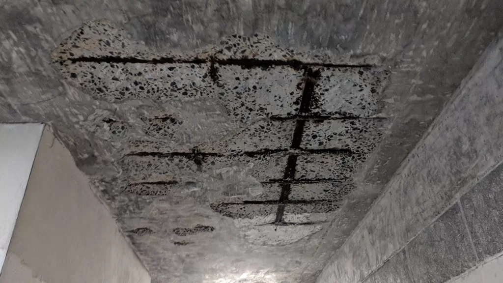
Reduced Durability: Cracks allow ingress of harmful substances like water and chlorides, which can lead to reinforcement corrosion and reduced lifespan of the structure.
Structural Weakness: Significant shrinkage and cracking can compromise the load-bearing capacity of concrete elements.
How to Reduce Shrinkage in Concrete
To reduce shrinkage and its adverse effects, consider the following measures:
Use Low Water-Cement Ratio: Reducing the amount of water in the mix decreases the potential for shrinkage. However, this must be balanced with workability requirements.
Use of Shrinkage-Reducing Admixtures: Incorporating admixtures can help reduce drying shrinkage and control crack widths.
Optimized Mix Design: Selecting appropriate types and proportions of cement and aggregates can influence shrinkage characteristics.
Environmental Control: Protecting concrete from extreme weather conditions, such as high temperatures and winds, can prevent rapid moisture loss.
Key Takeaways
Definition: The volume reduction due to moisture loss and hydration reactions.
Types: Includes plastic, drying, autogenous, thermal, and carbonation shrinkage.
Influencing Factors: Water-cement ratio, environmental conditions, and material properties.
Mitigation: Proper curing, shrinkage-reducing admixtures, and optimized mix designs are essential.
Importance: Effective shrinkage management preserves structural integrity, enhances durability, and ensures sustainable construction practices.
FAQs
What is concrete shrinkage?
It is the reduction in volume of concrete over time due to moisture loss and chemical reactions during cement hydration.
What causes this?
What are the types of concrete shrinkage?
The primary types include plastic, drying, autogenous, thermal, and carbonation shrinkage.
How can Concrete shrinkage be minimized?
What effects does concrete structures?
Shrinkage can cause cracking, reduce durability, and compromise the structural integrity and load-bearing capacity of concrete elements.
Conclusion
Concrete shrinkage involves a reduction in volume over time due to moisture loss. It also results from chemical reactions during hydration. This phenomenon poses a significant challenge for construction professionals. This blog has explored its various forms, including plastic, drying, autogenous, thermal, and carbonation shrinkage. The blog also examined the factors influencing shrinkage, such as water-cement ratio, environmental conditions, and material properties. Effective mitigation through proper curing, shrinkage-reducing admixtures, and optimized mix designs is crucial to prevent cracking and preserve structural integrity. By understanding these dynamics, engineers, contractors, and stakeholders can implement strategies that enhance durability and safety. Proactive management extends the lifespan of concrete structures. It also contributes to more resilient and sustainable construction practices. Ultimately, diligent control of shrinkage secures long-term performance and trust.
Concrete road construction involves building durable pavements using cement concrete road techniques, which prioritize strength and longevity. This method uses layered systems called concrete road layers, including subgrade, sub-base, base, and surface layers, to ensure stability and load distribution. Unlike asphalt, road construction concrete offers higher resistance to weather, heavy traffic, and wear, reducing long-term maintenance costs. Concrete for road construction is preferred for its sustainability, as it reflects sunlight, lowering urban heat, and uses recyclable materials. A cement concrete road lasts 30–40 years, outperforming flexible pavements in lifespan and cost-effectiveness. Engineers choose concrete road construction for highways and urban roads due to its minimal upkeep and eco-friendly benefits. By optimizing concrete road layers and material quality, this method delivers safer, smoother, and more reliable infrastructure.
This article explores concrete road construction, highlighting its layered design, durability, and sustainability. It explains why cement concrete roads outperform asphalt, offering long-lasting, eco-friendly, and cost-effective solutions for modern infrastructure needs.
Structural components of Concrete Road Construction
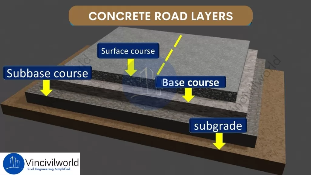
Concrete road construction relies on a well-structured system of layers to ensure durability and strength. These concrete road layers include the subgrade, sub-base, base course, and concrete slab. Each layer plays a critical role in distributing loads and preventing cracks. Proper road construction concrete techniques ensure the longevity of cement concrete roads, making them ideal for heavy traffic and harsh weather conditions. Let us explain each component in detail.
Concrete road construction – Layers
Subgrade
Engineers prepare the native soil to support the road structure, forming the subgrade. In concrete road construction, a stable subgrade is essential as it forms the foundation for all subsequent concrete road layers. Proper compaction of the subgrade prevents settlement and provides uniform support for the road construction concrete. A well-prepared subgrade enhances the durability of the cement concrete road by reducing the risk of cracks and deformations.
Sub-base
Positioned above the subgrade, the sub-base layer consists of granular materials like crushed stone or gravel. In concrete road construction, the sub-base serves to distribute loads and provides additional support to the upper concrete road layers. It also acts as a barrier against moisture, protecting the road construction concrete from potential damage. A properly installed sub-base enhances the overall performance of the cement concrete road.
Base Course
The base course lies directly beneath the concrete slab in concrete road construction. The base course consists of high-quality aggregates that create a stable platform for the pavement. It effectively transmits the loads from traffic to the underlying concrete road. Additionally, the base course plays a crucial role in enhancing the durability and performance of the pavement structure layers. A well-constructed base course is vital for the structural integrity of the cement concrete road, ensuring longevity and durability.
Concrete Slab (Pavement)
The concrete slab, or pavement, is the topmost layer in concrete road construction. This surface layer is made of road construction concrete and is designed to withstand direct traffic loads. The quality of the concrete for road construction used in this layer determines the road’s durability and service life. Proper curing and jointing of the concrete slab are crucial. These practices prevent cracks. They ensure a smooth, long-lasting cement concrete road surface.
Each of these layers is crucial in concrete road construction. They collectively enhance the pavement’s strength. They also improve its durability and longevity. Moreover, proper design and construction of these concrete road layers are essential to ensuring a high-quality cement concrete road. As a result, the pavement can effectively withstand the demands of heavy traffic. It can also endure varying environmental conditions. This ultimately provides a long-lasting and reliable transportation solution.
Types of Concrete Road Pavements
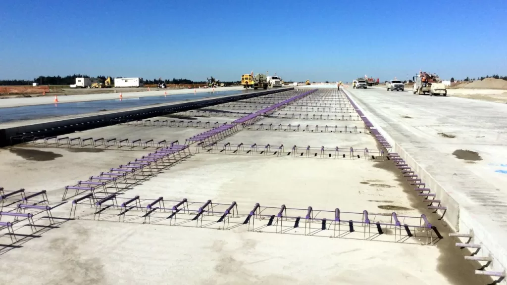
In concrete road construction, selecting the appropriate pavement type is crucial for durability and performance. There are three main types of concrete roads. These are Jointed Plain Concrete Pavement (JPCP), Jointed Reinforced Concrete Pavement (JRCP), and Continuously Reinforced Concrete Pavement (CRCP). Each type utilizes different concrete road layers and reinforcement methods to meet specific engineering requirements.
Jointed Plain Concrete Pavement (JPCP)
JPCP is the most commonly used type in concrete road construction. It consists of slabs with transverse joints spaced typically between 15 to 20 feet apart. These joints control cracking without the need for steel reinforcement. Dowel bars are often used to transfer loads across joints, enhancing the performance of the cement concrete road. The simplicity of design and construction makes JPCP a cost-effective choice for many road construction concrete projects.
Jointed Plain Concrete Pavement (JPCP)
Jointed Reinforced Concrete Pavement (JRCP)
JRCP incorporates steel reinforcement within the concrete slabs and features longer joint spacing, typically ranging from 30 to 40 feet. As a result, the reinforcement effectively helps control cracking between the joints, thereby maintaining the structural integrity of the pavement. Additionally, dowel bars and tie bars are strategically placed at transverse and longitudinal joints, respectively, to ensure efficient load transfer and proper alignment.
Moreover, this design is particularly suitable for areas experiencing heavier traffic loads, as it provides enhanced durability and long-term performance. Consequently, JRCP serves as a reliable cement concrete road solution, offering both strength and stability. Ultimately, its combination of reinforcement and optimized joint spacing makes it an excellent choice for modern road infrastructure.
Jointed Reinforced Concrete Pavement (JRCP)
Contraction Joints
These are intentionally placed joints in the concrete pavement to control where cracks occur. In JRCP, the spacing of transverse joints typically ranges from 25 to 50 feet (7.6 to 15.2 meters). These joints allow the concrete to shrink as it cures, reducing the likelihood of random cracking.
Reinforcing Steel
JRCP incorporates reinforcing steel or steel mesh to hold cracks tightly together. While the longer slab lengths in JRCP make cracking inevitable due to concrete’s natural shrinkage and thermal contraction, the reinforcing steel ensures that cracks remain tight and do not widen significantly. This helps maintain the pavement’s structural integrity and load-bearing capacity.
Dowel Bars
Dowel bars are used at transverse joints to facilitate load transfer between adjacent slabs. These bars allow for vertical movement while ensuring that loads are effectively transferred across the joint, reducing stress concentrations and preventing faulting (unevenness at the joint).
Load Transfer Across Cracks
The reinforcing steel or wire mesh in JRCP not only holds cracks together but also assists in transferring loads across the cracks. This helps distribute traffic loads more evenly, reducing the risk of localized damage and extending the pavement’s service life.
Advantages of JRCP
Crack Control: The combination of joints and reinforcement ensures that cracks are controlled and do not compromise the pavement’s performance.
Durability: The use of reinforcing steel and dowel bars enhances the pavement’s ability to withstand heavy traffic and environmental stresses.
Load Distribution: Effective load transfer mechanisms reduce the risk of joint faulting and slab cracking.
Disadvantages of JRCP
Cost: The inclusion of reinforcing steel and dowel bars increases material costs. Construction costs also rise compared to simpler pavement types like Jointed Plain Concrete Pavement (JPCP).
Maintenance: JRCP is designed to control cracking. However, the presence of reinforcing steel can complicate repairs if the pavement eventually fails.
In summary, JRCP is a robust pavement design. It uses a combination of contraction joints, reinforcing steel, and dowel bars. These elements manage cracking and ensure effective load transfer. This makes it suitable for roads and highways subject to heavy traffic and environmental stresses.
Continuously Reinforced Concrete Pavement (CRCP)
CRCP is the most advanced type in concrete road construction, as it features continuous steel reinforcements throughout the slab. Consequently, this design eliminates transverse joints, making it particularly ideal for high-traffic areas such as highways and airports. Additionally, CRCP uses reinforcement to hold tightly spaced cracks together, thereby creating a smooth and highly durable surface.
Continuously Reinforced Concrete Pavement (CRCP)
Moreover, CRCP concrete road construction is especially suitable for high-traffic areas because it offers superior performance while requiring minimal maintenance. As a result, this construction method ensures long-lasting pavement that can withstand heavy loads and harsh environmental conditions. Ultimately, its combination of strength, durability, and reduced upkeep makes CRCP a preferred choice for modern infrastructure projects.
CRCP offers exceptional durability and requires minimal maintenance for cement concrete roads. The steel mesh prevents cracks and distributes traffic loads evenly across concrete road layers, ensuring a smooth and long-lasting surface. CRCP uses high-strength road construction concrete to withstand heavy loads and extreme weather conditions. Its seamless design reduces maintenance costs and enhances the performance of concrete road construction, making it a top choice for critical infrastructure projects.
Choosing the appropriate type of concrete pavement depends on factors such as traffic load, environmental conditions, and budget considerations. Each type offers distinct advantages in concrete road construction, contributing to the development of durable and efficient transportation infrastructure.
Advantages of Concrete Roads
Concrete roads offer several advantages over other paving materials:
Durability and Longevity: Concrete roads are known for their exceptional durability, as they can withstand heavy traffic loads and adverse weather conditions. As a result, they offer a longer service life compared to other road construction materials. Furthermore, this durability ensures lower maintenance costs over time, making concrete roads a cost-effective option for long-term use.
Low Maintenance Requirements: Once constructed, concrete roads demand relatively low maintenance. Their resistance to wear and tear reduces the frequency of repairs, making them a cost-effective choice in the long run.
Resistance to Weathering and Heavy Loads: Concrete’s high stiffness and negligible wear and tear make it resistant to environmental factors such as water, extreme temperatures, and UV radiation. This resistance helps maintain the structural integrity of the road over time.
Improved Fuel Efficiency for Vehicles: Concrete roads are more economical to drive on in terms of fuel consumption, as they reflect light better and provide a smoother surface, contributing to better fuel efficiency for vehicles.
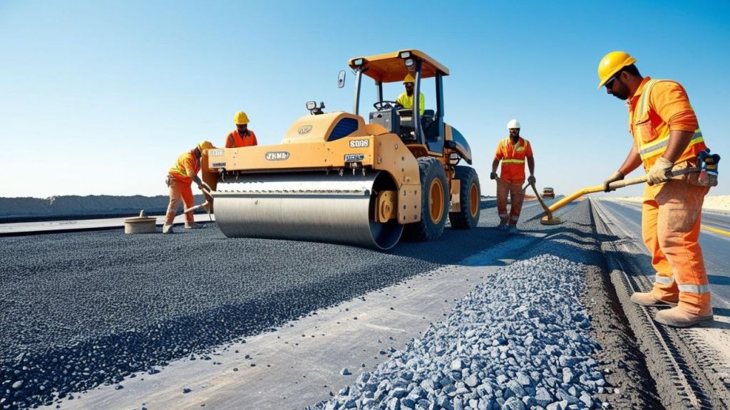
Methods of construction of cement concrete roads
Cement concrete roads are constructed through three primary methods, each designed to meet specific project requirements and conditions.
Alternate Bay Method
In this approach, the contractor divides the road into alternate bays, typically ranging from 6 to 8 meters in length. They construct the road in these alternate sections, ensuring each bay cures properly before constructing the adjacent bays. This method allows for effective curing and prevents premature construction, ultimately enhancing the quality of the road. This method helps in managing shrinkage and thermal stresses effectively, reducing the likelihood of cracks. However, it requires more time to complete since only alternate sections are worked on at a time. Additionally, during adverse weather conditions, water may collect in the unconstructed bays, potentially causing delays.
Continuous Bay Method
Also known as the strip method, this technique involves constructing the entire width of the road continuously without any breaks from one end to the other. Transverse joints, known as dummy joints, are provided at regular intervals (typically around 5 meters) to control cracking by creating planes of weakness. This method ensures a uniform surface and is suitable for projects requiring rapid completion. However, it necessitates careful planning to manage the setting time of concrete and to ensure proper curing across the entire stretch.
Expansion Joint and Strip Method
In this method, the engineers incorporate expansion joints at regular intervals to accommodate temperature-induced expansions and contractions. This prevents uncontrolled cracking and ensures the road remains structurally stable over time. By strategically placing these joints, they allow for controlled movement while maintaining the integrity of the pavement.These joints allow the concrete slabs to expand and contract with temperature variations without causing damage to the pavement. This technique is essential for long stretches of pavement, especially in regions experiencing significant temperature fluctuations. Proper placement and construction of these joints are crucial to maintain the structural integrity and longevity of the road.
Each method offers distinct advantages, and the choice depends on factors such as project scale, environmental conditions, and desired durability.
Steps involved in road construction
Constructing a cement concrete road involves several critical steps to ensure durability and longevity. Each phase plays a vital role in achieving a high-quality pavement.
Preparation of Subgrade
The subgrade is the native soil layer that serves as the foundation for the road. Preparation involves clearing the site of vegetation, debris, and any unsuitable materials. The soil is then leveled and compacted to achieve the desired density and strength. Proper subgrade preparation ensures uniform support for the pavement, preventing future settlement and distress. In cases where the subgrade soil is weak, stabilization techniques or additional layers may be applied to enhance its load-bearing capacity.
Placement of Formwork
Formwork refers to temporary molds used to shape and support the concrete until it hardens. In road construction, workers set sturdy forms along the edges of the proposed pavement to define its boundaries and maintain the desired thickness. They must accurately align and securely anchor these forms to withstand the pressure of the poured concrete. Consequently, proper formwork ensures consistent pavement dimensions and well-formed edges, contributing to the overall structural integrity.
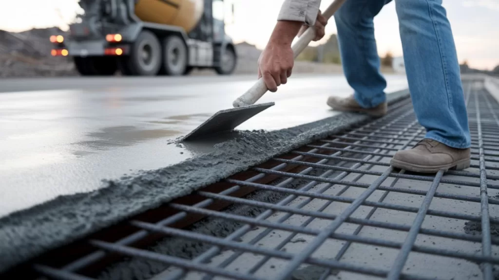
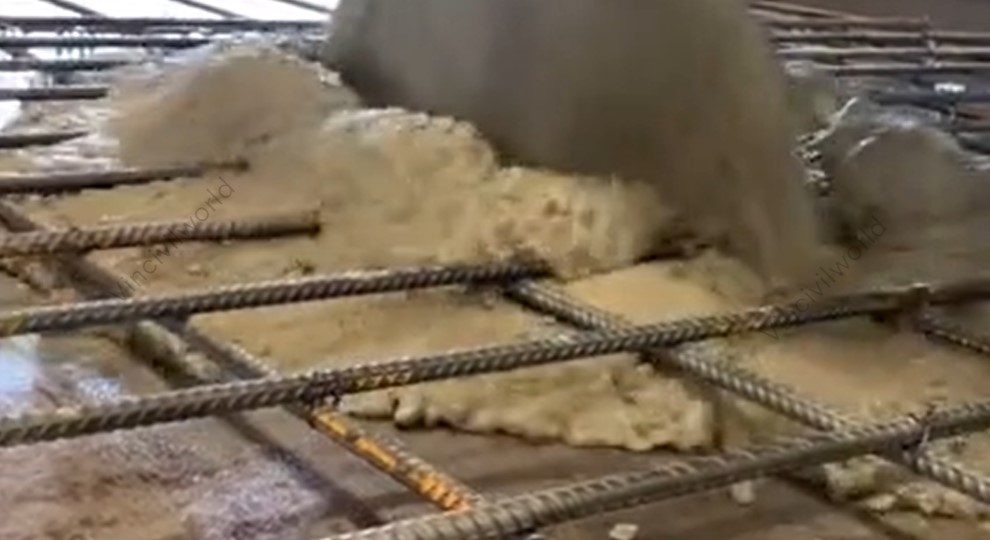
Mixing and Pouring of Concrete
Workers prepare concrete by mixing cement, aggregates (such as sand and gravel), water, and any necessary admixtures in specified proportions. They perform this mixing either on-site or at a batching plant. Afterward, they transport the mixed concrete to the site and pour it into the prepared formwork. It’s essential to pour the concrete promptly to prevent premature setting. Consistent mixing and timely pouring ensure a uniform composition, which is crucial for the pavement’s strength and durability
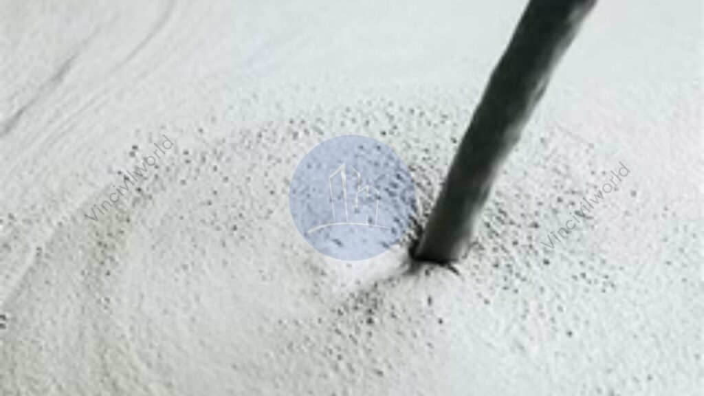
Compaction and Finishing
After pouring the concrete, workers must compact it to eliminate air voids and achieve the desired density. They typically use vibrators to ensure the concrete settles properly around any reinforcement and into all corners of the formwork. Following compaction, they level and smooth the surface using tools like screeds and trowels. Proper compaction is crucial, as it enhances the strength and durability of the concrete by removing entrapped air and consolidating the mixture. Finishing may also involve creating surface textures to enhance skid resistance. Proper compaction and finishing are vital for the pavement’s structural performance and surface quality.
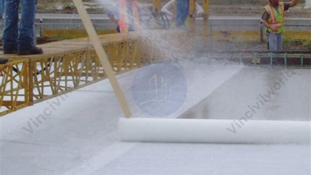
Curing Process
Curing involves maintaining adequate moisture and temperature conditions to allow the concrete to achieve its intended strength. This process typically lasts for several days and can be accomplished by methods such as covering the surface with wet burlap, applying curing compounds, or using plastic sheeting. Proper curing prevents the concrete from drying too quickly, which can lead to surface cracking and reduced durability. It’s a critical step to ensure the longevity of the pavement.
Joint Cutting and Sealing
Once the concrete has gained sufficient strength, joints are cut into the pavement to control cracking caused by temperature changes and shrinkage. These joints are typically spaced at regular intervals and can be of various types, including contraction, expansion, and construction joints. After cutting, workers thoroughly clean the joints and carefully apply appropriate sealants. This process effectively prevents the infiltration of water and debris, which could otherwise compromise the pavement’s integrity. Moreover, proper joint cutting and sealing play a crucial role in maintaining the road’s overall performance while significantly extending its service life.
Furthermore, each of these steps is essential for constructing a durable and long-lasting cement concrete road. By paying close attention to every phase, from preparation to finishing, workers ensure that the pavement can withstand heavy traffic loads and varying environmental conditions throughout its intended lifespan. Consequently, a well-executed construction process leads to stronger, more resilient roads that require minimal maintenance over time.
Disadvantages of concrete road construction
Concrete road construction offers durability and strength, but it also presents several challenges:
High Initial Construction Cost: Building concrete roads requires a significant upfront investment. This is due to the cost of materials and skilled labor.
Extended Construction Time: The curing process of concrete is time-consuming, leading to longer project durations compared to asphalt roads.
Difficulty in Maintenance: Repairing damaged concrete roads can be challenging. Often, it requires replacing entire slabs rather than simple patching.
Lower Comfort and Noise Issues: Concrete’s rigidity can result in a noisier and less comfortable driving experience due to its poor shock absorption and higher noise levels.
Susceptibility to Cracking: Concrete roads are prone to cracking under heavy loads and temperature variations, which can compromise their structural integrity over time.
These factors should be carefully considered when planning and implementing concrete road projects.
Maintenance Practices for Concrete Roads
Concrete road resurfacing and rehabilitation involve various methods to restore pavement functionality and extend service life:
Joint and Crack Sealing: Involves cleaning and filling existing joints and cracks with sealant to prevent water infiltration and debris accumulation, thereby reducing further deterioration.
Slab Stabilization: Addresses voids beneath concrete slabs by injecting grout to restore support and prevent faulting or cracking.
Diamond Grinding: Removes surface irregularities and restores smoothness by grinding the concrete surface, improving ride quality and skid resistance.
Partial-Depth Repair: Targets surface-level distress by removing and replacing the top portion of the slab, addressing issues like spalling.
Full-Depth Repair: Involves removing and replacing entire concrete slabs or sections to address severe damage extending through the slab.
Load Transfer Restoration: Enhances load distribution across joints by installing dowel bars, improving structural capacity and extending pavement life.
Concrete Overlays: Applies a new concrete layer over existing pavement to increase structural capacity and address surface deficiencies.
Selecting the appropriate method depends on the pavement’s condition, distress types, and project objectives.
Innovations and Future Trends in Concrete Road Construction
Smart concrete and self-healing materials represent significant advancements in construction technology. Key points include:
Self-Sensing Capabilities: Smart concrete can monitor its own structural health. It does so by embedding sensors or conductive materials. This allows it to detect stress or damage in real-time.
Self-Healing Mechanisms: Incorporating materials like superabsorbent polymers or specific bacteria enables the concrete to autonomously repair cracks, enhancing durability and reducing maintenance needs.
Environmental Benefits: Extending the lifespan of structures and reducing the need for repairs contribute to sustainability in construction.
Enhanced Durability: Self-healing properties allow the concrete to recover from internal damage without external intervention, limiting reinforcement corrosion and concrete deterioration.
Innovative Additives: The use of carbon nanotubes, mineral admixtures, and shape memory alloys improves the unique properties of smart concrete.
These innovations aim to create more resilient, sustainable, and low-maintenance infrastructure.
Key Takeaways
Concrete road construction offers unparalleled durability and longevity, often lasting 20-40 years, which is two to four times longer than asphalt roads.
This longevity translates to lower maintenance costs over time, making it a cost-effective choice for modern infrastructure. The typical layered design—comprising subgrade, sub-base, base, and concrete slab—ensures exceptional strength and stability. Although the initial investment is higher compared to asphalt, the long-term savings and environmental benefits make concrete road construction a wise investment. Innovations such as self-healing concrete, which can repair its own cracks, further enhance performance and extend service life.
Proper curing, jointing, and high-quality materials are critical to success. Despite challenges like cracking and temperature sensitivity, concrete road construction remains a reliable solution for highways, urban roads, and industrial zones, ensuring safe and sustainable travel for decades.
Conclusion
Concrete road construction is a cornerstone of durable and sustainable infrastructure. Its ability to withstand heavy traffic, harsh weather, and long-term wear makes it ideal for modern roadways. By optimizing concrete road layers and using high-quality materials, engineers can create pavements that last 30–40 years with minimal maintenance. While challenges like cost and cracking exist, advancements in technology and construction techniques continue to improve its efficiency and performance. Embracing concrete road construction ensures safer, smoother, and more eco-friendly roads, paving the way for resilient and future-ready transportation networks.
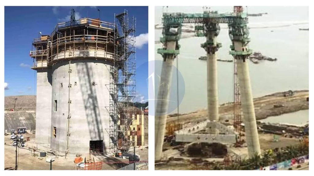
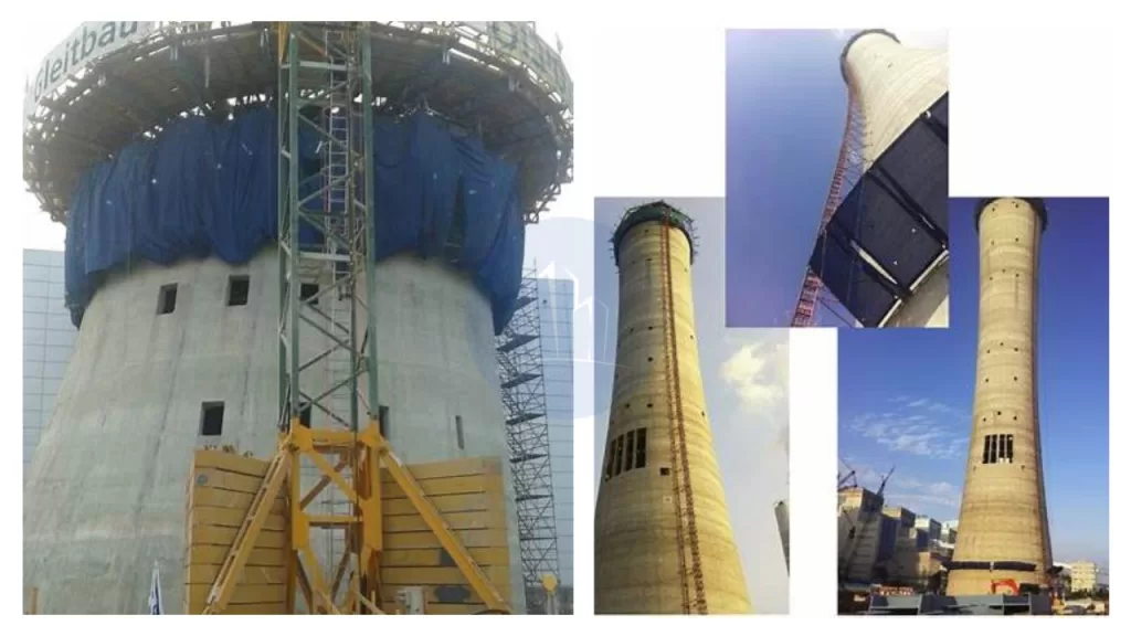
Slipform shuttering is a continuous construction method. In this method, concrete is poured into a continuously moving formwork. This allows for the seamless creation of vertical structures. This technique, known as slipforming, enables the efficient construction of tall edifices such as silos, chimneys, and core walls in high-rise buildings. By employing slipform formwork, builders can achieve monolithic structures without horizontal joints. This method enhances the overall strength and durability of the construction.
The slipform formwork construction process involves the gradual and steady upward movement of the formwork system. This movement is synchronized with the setting rate of the concrete. This ensures that as the formwork ascends, the concrete below has gained sufficient strength to support itself. The continuous nature of slipform shuttering not only accelerates the construction timeline but also reduces labor costs and minimizes the need for scaffolding, making it a preferred choice for large-scale vertical constructions.
The blog will explore the definition and principles of Slipform shuttering, its key components, and the process of slipforming. We will highlight its advantages, common applications, and critical considerations for effective use. Additionally, we will discuss how Slipform formwork construction enhances efficiency and provide insights into best practices for successful implementation.
Slipform shuttering is an advanced construction technique. It enables the continuous pouring of concrete for vertical structures like silos, chimneys, and high-rise cores. The method employs slipform formwork construction, where the formwork system moves steadily upward, synchronized with the concrete’s setting time. This ensures seamless, monolithic structures without horizontal joints.
Significance and Development
The development of slipforming revolutionized construction by enhancing efficiency and reducing project timelines. This method eliminates the need for scaffolding, minimizes labor costs, and ensures structural integrity. Slipform shuttering has become integral in modern construction. It is especially useful for projects requiring tall, uniform structures. This is due to its ability to streamline processes while maintaining high-quality results.
Slipform formwork construction
The slipform formwork construction method basically rely on the following factors
Slipform formwork construction
Continuous Pouring and Synchronized Upward Movement
In slipform shuttering, concrete is poured continuously into a moving formwork system, which climbs steadily as the concrete sets. This synchronized upward movement ensures a seamless structure, eliminating horizontal joints and enhancing strength.
Importance of Concrete Setting Time
The climbing speed of the formwork is carefully calibrated to match the concrete’s setting time. If the formwork ascends too quickly, the concrete may deform due to insufficient strength. Conversely, if it moves too slowly, delays and uneven surfaces can occur. Maintaining this balance is crucial for structural integrity and efficiency. Proper synchronization is essential. It ensures that the concrete beneath the formwork gains enough strength to support its weight. It also needs to withstand construction loads during the process.
Historical Development of Slipform formwork construction
Slipforming has a rich history dating back to the early 20th century. The first slipform systems were primarily used for concrete roads and canals. Over the years, significant technological advancements have led to the development of sophisticated slipform systems that can handle complex structures and challenging environments. Some key milestones in the development of slipforming include:
Early 20th Century: The first rudimentary slipform systems were used for road and canal construction.
Mid-20th Century: The introduction of hydraulic systems and improved concrete technology paved the way for more efficient and versatile slipform systems.
Late 20th Century: The development of computer-controlled slipform systems further enhanced precision and accuracy.
21st Century: Continued advancements in automation, robotics, and material science are leading to even more sophisticated and sustainable slipform systems.
Key components of slipform system
In slipform shuttering, several key components work together to facilitate continuous concrete construction:
Formwork Panels: These vertical molds shape the concrete as it’s poured, ensuring the desired dimensions and surface finish. As the formwork ascends, the panels move upward at a controlled rate, allowing the structure to rise seamlessly.
Jacking Systems: Hydraulic or pneumatic jacks lift the formwork incrementally. They support the formwork, platforms, crew, and withstand the hydrostatic pressure of the fresh concrete. The placement of jacks depends on vertical forces and lateral pressures, ensuring stability during the slipforming process.
Working Platforms: These platforms provide safe and accessible areas for workers to perform tasks such as pouring concrete, monitoring alignment, and managing reinforcement. They move in tandem with the formwork, maintaining consistent working conditions.
Support Structures: Elements like yokes and whalers distribute loads from the formwork and jacking systems, maintaining structural integrity. Yokes connect the formwork to the jacks, while whalers reinforce the formwork panels, ensuring even pressure distribution.
Concrete Placement Equipment: Conveying systems like concrete pumps or chutes ensure continuous concrete delivery to the formwork.
Vibration System: Compacts the concrete within the formwork, eliminating air pockets and ensuring a uniform density.
The cohesive interaction of these components enables the efficient construction of vertical structures. These structures are continuous and without joints. This process enhances both speed and structural integrity.
Types of slipform shuttering
Slipform shuttering encompasses several types, each tailored to specific construction needs. The most common types of slipform shuttering types are as follows
Vertical slipform shuttering
Horizontal Slipform shuttering
Tapered slipform
Conical slipform
Egg shaped slipform
Cantilever type
Vertical Slipform
Builders use vertical slipform to construct tall structures, such as silos, chimneys, or towers. They employ a moving formwork system that continuously ascends as they pour concrete. Workers gradually raise the formwork using hydraulic jacks, ensuring a smooth and consistent construction process.This method allows for the creation of vertical concrete structures without the need for scaffolding or traditional formwork systems. As the concrete sets, the formwork slips upwards, maintaining a uniform shape. Vertical slipform is efficient for projects requiring rapid construction, offering enhanced safety and reduced labor costs. It also ensures high-quality finishes and precise dimensions, making it suitable for large-scale industrial and infrastructure projects.
Slipform shuttering /slipforming
Horizontal Slipform shuttering
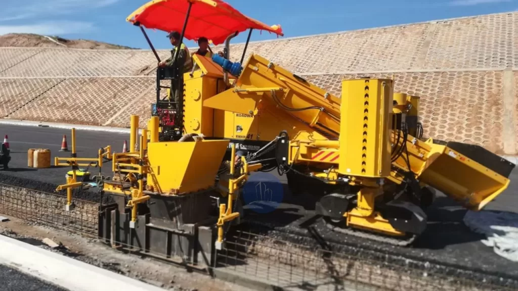
This technique is utilized in constructing horizontal structures such as road pavements and bridge decks. It allows the formwork to move horizontally. This movement enables continuous concrete placement along the structure’s length. Workers use horizontal slipform to create continuous concrete elements such as pavements, curbs, drainage channels, and safety barriers. This method involves the extrusion of concrete in situ, allowing for uninterrupted casting of long sections.
A specially designed machine has a mold with the required dimensions. It is equipped with vibrators for concrete compaction and moves forward at a controlled rate. The machine powers itself and mounts on wheels or tracks, ensuring stability during operation. As workers pour concrete from the rear of the machine, it becomes self-supporting. The machine follows a prefixed guide wire to achieve the correct line and level. This approach offers advantages such as speed, the ability to produce monolithic structures, and operational economy.
Horizontal slipform formwork construction
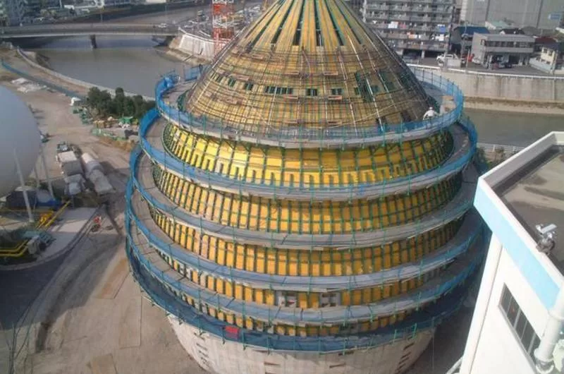
Tapered Slipform shuttering
This method is designed for structures with varying cross-sections, such as conical chimneys and cooling towers. It adjusts the formwork dimensions during the slipforming process. This adjustment achieves the desired tapering effect.
Builders use tapered slipform to create structures with a gradually narrowing shape. Examples include chimneys, cooling towers, and tall industrial structures. They employ movable formwork that adjusts in size as it rises, allowing for a tapered design. Similar to vertical slipform, workers pour concrete continuously as the formwork rises, typically using hydraulic jacks or other lifting mechanisms. Engineers design the formwork carefully to accommodate the structure’s changing cross-section, ensuring a precise and smooth taper.This method offers efficiency in construction, as it reduces the need for complex scaffolding and allows for a seamless, uniform finish. Tapered slipform is ideal for projects requiring strong, stable, and visually appealing tapered structures.
Tapered construction
Conical Slipform shuttering
Builders use conical slipform to construct structures with a conical shape, such as cooling towers or silos. They use a moving formwork that continuously ascends as workers pour concrete. Workers shape the formwork to create a gradual narrowing toward the top. This process forms the cone. Workers raise the formwork using hydraulic jacks or other lifting mechanisms as the concrete cures, ensuring a smooth and consistent structure. This approach is highly efficient, as it eliminates the need for scaffolding and enables continuous, uninterrupted pouring. Conical slipform offers precise control over the shape and finish. It is ideal for large-scale, high-strength structures with conical geometry. It also reduces labor costs and construction time.
Egg-shaped Slipform
Engineers use egg-shaped slipform to create structures with an elliptical or egg-like shape. These structures include certain types of silos, industrial towers, and water or wastewater treatment facilities. They utilize specially designed formwork that moves vertically as workers pour concrete continuously. The formwork is shaped to create the unique, rounded profile of the egg shape, gradually narrowing at the top. Workers raise the formwork using hydraulic jacks or other lifting mechanisms, ensuring smooth and consistent construction. Egg-shaped slipform provides benefits like efficient construction with minimal labor, reduced material waste, and precise control over the shape. This technique is particularly suitable for structures requiring unique, aerodynamic designs, offering both functional and aesthetic advantages.
This method enables builders to construct structures that extend horizontally beyond their supports. These structures include certain bridge segments. It also allows them to build overhanging elements without the need for additional support scaffolding.
In cantilever slipform, construction teams use a method to build structures with an overhanging or projecting shape, such as bridges, dams, and tall towers. They gradually move the formwork system upwards while pouring concrete continuously. The structure itself supports the formwork, which extends outward as it rises, creating a cantilever effect. This technique is ideal for projects where workers have limited access to both sides of the structure or when constructing from the top down. Cantilever slipform ensures a precise and smooth finish, with high structural integrity. It reduces the need for scaffolding or external supports, making it an efficient and cost-effective method for large-scale projects that require overhanging sections or complex geometries.
Cantilever slipforming
Engineers design each type of slipform shuttering to meet specific architectural and structural demands, enhancing construction efficiency and quality.
Advantages of Slipform Formwork Construction
Slipform shuttering offers several advantages in construction, making it a preferred method for certain types of structures. Some key benefits include:
Speed and Efficiency: Continuous pouring and raising of formwork allow for faster construction, reducing overall project timelines.
Cost-Effective: It minimizes labor costs by eliminating the need for scaffolding and extensive formwork, resulting in a more economical process.
High Quality: The method provides a smooth, consistent finish with high precision and uniformity in dimensions.
Safety: With less reliance on manual labor and scaffolding, slipform offers enhanced safety for workers during construction.
Minimal Material Wastage: The continuous nature of the process reduces material waste, making it more environmentally friendly.
Reduced Need for Supervision: Automated or semi-automated systems reduce the need for constant supervision, leading to better management of resources.
Versatility: Suitable for a variety of structures, including vertical, tapered, conical, and curved shapes, making it adaptable to different project requirements.
Monolithic Structures: Slipform allows for the construction of monolithic concrete elements, improving the structural integrity of the finished project.
Durability: The seamless construction process ensures strong, durable structures with fewer weak points.
Reduced Labor Dependency: The method relies on machinery, reducing the need for large labor forces and improving construction consistency.
Challenges and disadvantages of Slipform Shuttering
While slipforming offers numerous advantages, it also presents several challenges that need to be carefully managed to ensure successful implementation.
High Initial Setup Costs: The machinery, formwork, and equipment required for slipforming can be costly. This leads to high upfront investments. Such investments may not be feasible for smaller projects.
Complexity in Design: Formwork design must be highly precise and adaptable to varying shapes and sizes. Skilled engineering and planning are necessary to meet specific project requirements.
Skilled Labor: Skilled operators are crucial for proper alignment. They ensure smooth operation. The availability of experienced personnel is essential for effective slipforming.
Concrete Quality Control: Maintaining consistency in concrete mix and quality is vital. Any variation in material quality, mix ratios, or curing methods can negatively impact the structure’s integrity.
Weather Conditions: Unfavorable weather, such as heavy rain or freezing temperatures, can disrupt the slipforming process. It can also affect concrete curing. This necessitates careful planning and adjustments.
Continuous Supervision: Despite automation, slipforming systems still require constant monitoring to address potential malfunctions or adjustments during the process.
Site Access: Limited access to construction sites can make it challenging to transport the necessary machinery and materials.
By addressing these challenges with proper planning, slipforming can be an efficient construction method. Skilled labor and risk management also contribute to its effectiveness.
Applications of Slipform shuttering
Slipform shuttering is a versatile construction technique. It is employed across various industries for its efficiency. It also has the ability to create continuous, seamless structures. Key applications include:
High-Rise Building Cores: Slipform is ideal for constructing the core walls of high-rise buildings. It enables rapid and uniform construction of elevator shafts and stairwells.
Chimneys and Cooling Towers: The method is extensively used for building tall, tapered structures like chimneys and cooling towers. It ensures consistent quality and structural integrity.
Silos and Tanks: Slipform facilitates the construction of large storage silos and tanks. It provides a cost-effective and efficient solution for industries requiring bulk storage.
Bridges: Bridge piers and abutments benefit from slipform construction, allowing for continuous pouring and reducing the need for formwork stripping.
Roadways and Pavements: In highway construction, slipform is used to build continuous pavements, curbs, and barriers. This technique enhances construction speed. It also improves surface uniformity.
Dams: Slipform technology is applied in constructing concrete-faced dams, enabling efficient and continuous pouring of concrete.
Water Towers: The technique is employed to construct the walls of water towers, ensuring uniformity and structural strength.
Offshore Structures: Slipform is utilized in the construction of offshore platforms and structures, providing a robust and continuous concrete shell.
These applications highlight the versatility and efficiency of slipform shuttering in modern construction projects.
Advancements in slipform construction
Advancements in automation and real-time monitoring have significantly enhanced slipform shuttering processes. Integrating automated systems with real-time concrete monitoring allows for precise adjustments during construction, ensuring optimal curing conditions and structural integrity. By embedding sensors within the concrete, teams can monitor parameters like temperature and strength, enabling timely interventions and reducing delays.
Additionally, innovations in materials and formwork technology have improved efficiency and safety. Modern formwork systems are designed to be cost-effective, lightweight, reusable, and easy to assemble and dismantle. These advancements contribute to faster construction times and enhanced structural performance.
Collectively, these developments modernize construction practices by increasing efficiency, reducing costs, and ensuring higher-quality outcomes.
Conclusion
Slipform shuttering has revolutionized modern construction by enabling continuous, efficient, and precise building of complex structures. Its key benefits include faster construction timelines and reduced labor costs. It also minimizes material wastage and improves safety by eliminating the need for scaffolding. The method ensures a smooth, uniform finish. It is highly adaptable to various structural shapes. These include high-rise cores, chimneys, silos, cooling towers, bridges, and dams. It is particularly effective for projects requiring repetitive, large-scale concrete pouring. Slipform shuttering reduces manual labor. It optimizes resource use and modernizes construction practices. These improvements make construction practices more cost-effective, environmentally friendly, and precise. Its efficiency and scalability are crucial for meeting the demands of large infrastructure projects in today’s fast-paced construction industry.
Self-Compacting Concrete (SCC) flows effortlessly and fills complex formwork without requiring external vibration, thanks to its advanced mix design. But what is Self Compacting Concrete? It’s a high-performance concrete that uses a blend of cement, aggregates, and superplasticizers to achieve its self-leveling and self-consolidating properties.
The advantages of SCC are significant. Self Compacting Concrete simplifies placement and improves workability. It reduces the need for manual vibration and thereby cuts labor costs and lowers the risk of defects like honeycombing. This makes SCC ideal for intricate and congested structures such as high-rise buildings, bridges, and underground constructions.
The application of Self-Compacting Concrete enhances construction efficiency by ensuring uniform compaction and a high-quality finish. SCC is a game-changer in concrete technology. Self Compacting concrete provides robust solutions for demanding construction scenarios. It also improves overall structural performance and cost-effectiveness. In this article we are will go through the definition , characteristics, advantages , mix design etc of Self compacting concrete (SCC).
Definition and Characteristics of Self-Compacting Concrete (SCC)
Self-Compacting Concrete (SCC) is a high-performance concrete that doesn’t require external vibration for placement. So, what is Self-Compacting Concrete? This type of concrete flows and consolidates under its own weight, effortlessly filling complex forms and tight spaces.
SCC is known for several distinctive properties:
High Flowability: It spreads and fills molds and congested areas with ease.
Low Viscosity: This allows SCC to flow around obstacles and through narrow openings without segregating.
High Passing Ability: It moves smoothly through narrow openings and congested areas.
Excellent Cohesiveness: SCC maintains a homogeneous mixture, preventing segregation.
Self-Consolidation: It eliminates the need for external vibration, reducing noise and labor during placement.
These characteristics make SCC ideal for various applications. The use of Self-Compacting Concrete improves placement efficiency. It also enhances quality control. These benefits lead to reduced labor costs and greater structural integrity.
Self Compacting Concrete
Advantages of Self-Compacting Concrete
The main advantages of Self Compacting Concrete are..
Improved Workability
Self-compacting concrete offers superior workability, eliminating the need for vibration. This significantly reduces labor costs and time required for placement, particularly in complex and congested areas.
Enhanced Durability
The homogenous nature of self-compacting concrete results in a denser and more durable structure. Its ability to fill intricate molds and intricate shapes without voids ensures optimal strength and longevity.
Reduced Labor Requirements
Due to its self-consolidating properties, self-compacting concrete requires less manual intervention, reducing labor needs and potential errors. This translates into cost savings and faster construction schedules.
Improved Surface Finish
Self-compacting concrete eliminates the need for vibration, resulting in a smoother and more uniform surface finish. This is particularly beneficial for exposed concrete structures, where aesthetics are crucial.
Self Compacting Concrete – Ingredients and Mix design
The composition of self-compacting concrete (SCC) is carefully tailored to achieve its unique properties. It involves a precise combination of aggregates, cement, water, and chemical admixtures. The key to SCC’s success lies in the optimal proportioning of these ingredients, ensuring a balanced mix that is highly flowable, stable, and resistant to segregation.
Aggregates
SCC utilizes a well-graded aggregate blend, typically consisting of fine and coarse aggregates. Fine aggregates, such as sand, provide cohesion and fill the voids between coarse aggregates, which provide strength and stability. The grading of aggregates plays a crucial role in ensuring a homogeneous mix that flows smoothly without segregating.
Cement
The type and amount of cement used in SCC are crucial for achieving the desired strength and workability. However, high-quality cement is preferred for SCC. It often has a high fineness and low setting time. This ensures rapid strength development and prevents early setting.
Water
The water content is carefully controlled in SCC to achieve the desired slump flow and prevent excessive bleeding. Insufficient water can lead to a stiff mix, while excessive water can lead to segregation and a reduction in strength.
Chemical Admixtures
SCC typically incorporates various chemical admixtures to enhance its properties and ensure proper performance. These admixtures can include superplasticizers to improve flowability. They also reduce water content. Viscosity-modifying agents control the mix’s consistency. Air-entraining agents enhance freeze-thaw resistance.
Mineral Admixtures :Different mineral admixtures used in self-compacting concrete (SCC) contribute various properties, thereby enhancing its performance based on specific requirements
Ground Granulated Blast Furnace Slag (GGBS): Improves the rheological properties, making SCC more flowable and easier to place.
Fly Ash: Fills internal voids, reducing pores, which enhances the quality and durability of SCC structures.
Silica Fumes: Increases the mechanical properties, leading to stronger SCC structures with higher resistance.
Stone Powder: Enhances the powder content, improving the overall mix and cohesiveness of SCC.
Determining the appropriate Mix Design for self compacting concrete requires a detailed process. It involves careful consideration of the project’s specific requirements. These requirements include the target strength, flowability, and durability. The self compacting concrete mix design is typically based on laboratory testing. Simulation ensures that the SCC meets the desired performance criteria. The mix proportions are often adjusted. Variations in the properties of the materials used are considered. Environmental conditions during placement are also taken into account.
Performance parameters of self-compacting concrete (SCC)
Performance parameters of self-compacting concrete (SCC) include flowability and passing ability. Segregation resistance and setting time are also essential. They are crucial for optimal quality and efficiency. Let us go through in detail.
Flowability and Passing
Viscosity and Segregation Resistance
Flowability and Passing Ability of Self Compacted Concrete
Both are key parameters in evaluating self-compacting concrete (SCC). Flowability refers to the concrete’s ability to flow smoothly under its own weight, filling formwork without segregation. Passing ability measures the concrete’s capacity to move through narrow openings and congested reinforcement without obstruction. These properties ensure that SCC fills the formwork uniformly, creating a dense structure.
Self Compacting Concrete
Factors such as rheological properties, particle size distribution, and admixtures influence both flowability and passing ability. Standardized tests such as the L-box and V-funnel tests assess these qualities. The L-box test measures the concrete’s ability to flow horizontally through a restricted area. The V-funnel test evaluates how quickly the concrete passes through a vertical funnel.
Optimizing these properties ensures a smooth flow, producing a durable, homogenous concrete structure with improved strength and performance.
Viscosity and Segregation Resistance
Viscosity in self-compacting concrete (SCC) is crucial for its flowability and homogeneity during placement. SCC’s high viscosity helps prevent segregation, where heavier aggregates settle, weakening the mixture. Segregation resistance is another key aspect. Segregation resistance means SCC can resist the separation of components. These components include cement paste, aggregates, and water during transport and placement.
Viscosity ensures the mixture stays stable and uniform, resulting in a durable structure. Factors influencing SCC’s viscosity include admixture type and dosage, water-to-cement ratio, aggregate size and shape, and temperature. Proper control of these factors is essential for achieving optimal viscosity and segregation resistance.
Testing methods like the slump flow, V-funnel, and L-box tests assess SCC’s viscosity and segregation resistance. These tests provide critical insights into the concrete’s flow characteristics and suitability for specific applications.
Testing Methods and relevant standards for Self-Compacting Concrete
Testing methods for self-compacting concrete (SCC) ensure that the concrete meets the required performance parameters for flowability, cohesiveness, and stability. Both Indian and international codes provide guidelines for these tests to ensure consistent quality and performance. Here’s an overview of the key testing methods and relevant codes.
Testing methods are crucial for ensuring the quality and performance of self-compacting concrete (SCC). These tests evaluate various properties of SCC, including its flowability, passing ability, viscosity, segregation resistance, and compressive strength.
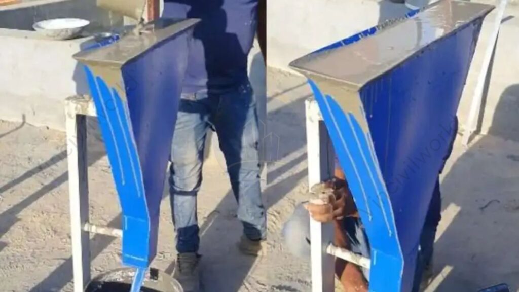
V-Funnel Test
The most common test for flowability is the V-funnel test. It measures the time it takes for a predetermined amount of concrete to flow through a V-shaped funnel. This test assesses the concrete’s ability to spread easily and fill complex shapes.
Indian Standard: IS 9103: 1999
International Standard: JIS A 1128 (Japan)
V- Funnel Test for SCC
L-Box Test
The L-box test assesses the passing ability of SCC, measuring its capacity to flow through narrow openings and congested areas. This test involves placing the concrete in a box with a horizontal opening. The next step is measuring the time it takes for the concrete to pass through.
Indian Standard: No specific standard; often aligned with international practices.International Standard: EN 12350-10 (Europe)
J -Ring Test
To evaluate the viscosity of SCC, the J-ring test is often employed. In this test, the concrete is placed in a J-shaped ring. The time it takes for a portion of the concrete to settle to the bottom is then measured. This test helps determine the concrete’s resistance to flow and its ability to maintain its shape.
International Standard: EN 12350-12 (Europe)
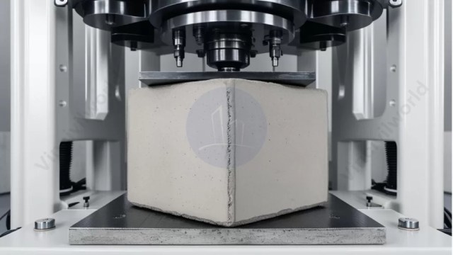
Finally, the compressive strength test assesses the concrete’s load-bearing capacity. This test involves subjecting a concrete cylinder to a compressive force until it fails. The resulting compressive strength value indicates the concrete’s ability to withstand external pressures.
Testing methods for self-compacting concrete are critical to ensure it performs as expected in various applications. Practitioners should adhere to both Indian and international codes, such as those from IS, ASTM, JIS, and EN. This adherence ensures SCC meets the required standards for flowability, cohesiveness, and structural integrity.
Application Areas of Self-Compacting Concrete
1. Complex Structures
Self-compacting concrete excels in intricate structures with congested reinforcement. It is ideal for columns with dense rebar arrangements. It also works well for precast elements with complex geometries. It can flow and fill the formwork without vibration. This ability significantly reduces the risk of voids and defects. It ensures high-quality concrete in these challenging applications.
2. Thin-walled Structures
Self-compacting concrete is ideal for thin-walled structures, such as precast walls, panels, and beams. It eliminates the need for excessive vibration, which can damage these delicate elements. The concrete’s ability to flow evenly and compact itself ensures uniform thickness and prevents cracking or delamination.
Self Compacting Concrete
3. Large-scale Projects
Large-scale infrastructure projects, such as bridges, dams, and tunnels, benefit greatly from the efficiency and effectiveness of self-compacting concrete. Its high flowability allows for rapid placement, reducing downtime and accelerating construction schedules. Additionally, it minimizes labor requirements, leading to cost savings and enhanced productivity.
4. Repair and Rehabilitation
Self-compacting concrete plays a crucial role in the repair and rehabilitation of existing structures. Its ability to penetrate cracks and fill voids effectively ensures durable and long-lasting repairs. It is especially valuable for restoring concrete structures damaged by wear and tear. Environmental factors or seismic events also cause damage.
Placement and Finishing Techniques of Self Compacting Concrete
Placing and finishing self-compacting concrete (SCC) requires specific techniques due to its unique properties. Unlike conventional concrete, SCC’s high flowability and self-compacting nature necessitate careful handling and finishing methods to achieve optimal results.
The placement of SCC typically involves pumping or conveying the concrete directly into the formwork. This process minimizes segregation and ensures uniform distribution of the concrete mixture. In some cases, placing SCC using a crane or a bucket is also possible. However, it’s crucial to avoid dropping the concrete from a height as this can lead to segregation and air entrainment.
Finishing SCC requires specialized techniques to achieve a smooth and even surface. Due to the concrete’s high flowability, traditional troweling and screeding methods are less effective. Instead, vibrators commonly consolidate the concrete and eliminate air bubbles. Specialized finishing tools, such as vibrating screeds, are also available to achieve a smooth and consistent finish.
The use of vibrating screeds helps to compact the concrete. It removes air voids, leading to a smooth and even surface finish.
In some cases, achieving the desired surface finish may require a combination of hand finishing techniques. These can include methods such as troweling or floating.
It’s important to ensure proper compaction of the concrete during placement. Consolidate it properly during finishing to prevent cracking and other defects.
Curing and Strength Development of Self Compacting Concrete
Curing is a vital step in the life cycle of self-compacting concrete (SCC). It significantly impacts its strength development. It also affects its long-term performance. It ensures that moisture and temperature are maintained, promoting the hydration process that binds the concrete. SCC usually needs at least 7 days to develop initial strength. Longer periods are recommended for optimal strength and durability.
Different curing methods are available for use. These include water curing, plastic sheets, curing compounds, and steam curing. The choice depends on project needs and environmental conditions. Factors such as cement type, water-cement ratio, aggregate size, and curing conditions influence SCC’s strength. Generally, higher cement content and lower water-cement ratios lead to greater strength. Admixtures like superplasticizers and silica fume can significantly improve strength development. They ensure better performance and durability of the concrete structure.
Compressive Strength
Compressive strength is essential for evaluating concrete performance. It is measured in units of pounds per square inch (psi) or megapascals (MPa). SCC normally reaches compressive strengths from 3,000 to 8,000 psi (20 to 55 MPa). These levels can go higher, depending on the mix design and curing conditions. The compressive strength of SCC is determined by standardized testing methods, such as ASTM C39 or EN 12390-4.
Durability and Sustainability of Self Compacting Concrete
Self-compacting concrete (SCC) offers significant advantages in terms of durability. It also enhances sustainability. This contributes to the longevity and environmental friendliness of structures. Its inherent properties promote long-term performance and minimize environmental impact.
SCC’s excellent workability and compaction ensure a dense and homogeneous concrete matrix, reducing the occurrence of voids and micro-cracks. This improves the concrete’s resistance to permeability. It also prevents the ingress of harmful substances like chlorides and sulfates. These substances can lead to deterioration over time.
The use of high-quality aggregates improves SCC resistance to abrasion. Optimized mixture proportions also enhance its resistance to freeze-thaw cycles and chemical attack. These characteristics are crucial for structures exposed to harsh environments, such as coastal areas or industrial sites.
The reduced use of water in SCC mixtures compared to conventional concrete minimizes the potential for shrinkage cracking. This contributes to the overall structural integrity and durability of the concrete.
SCC’s excellent flowability allows it to fill intricate formwork and complex geometries, reducing the need for vibration and manual compaction. This minimizes noise and vibration pollution during construction, enhancing sustainability and reducing the carbon footprint.
By promoting durability and sustainability, SCC contributes to the longevity of structures. It also enhances the environmental friendliness of structures. These factors make it a preferred choice for various applications in modern construction.
Environmental Impact and Recycling of Self Compacting Concrete
Self-compacting concrete (SCC) offers several environmental benefits compared to traditional concrete. It eliminates the need for vibration, reducing noise pollution and fuel consumption during construction. Its enhanced workability minimizes waste and lowers the volume of concrete needed, cutting carbon emissions from production and transportation.
SCC’s environmental impact is further reduced by its recyclability. Aggregates and cement can be reclaimed and reused, lessening the need for virgin materials. SCC’s high flowability allows for the use of recycled aggregates, supporting sustainable construction practices.
To further reduce SCC’s environmental footprint, sustainable production methods should be employed. These methods include using recycled materials, optimizing cement content, and adopting low-carbon cement alternatives. Efficient production and transportation processes also help decrease emissions, promoting a more eco-friendly construction sector.
Quality Control and Assurance
Material Testing
Ensuring the quality of concrete materials is crucial for the performance and longevity of self-compacting concrete structures. This involves thorough testing of aggregates, cement, admixtures, and water to ensure they meet the specified requirements. Standardized tests are employed to determine properties like compressive strength, water absorption, and particle size distribution.
Slump Flow and V-Funnel Tests
Flowability and segregation resistance of SCC are assessed using tests like the slump flow test and the V-funnel test. These tests evaluate the concrete’s ability to flow evenly and resist segregation during placement. They provide valuable insights into the mix design and help ensure that the concrete achieves the desired consistency and performance.
Visual Inspection
Visual inspection plays a vital role in quality control for SCC. Experienced personnel assess the concrete mix during batching, mixing, and placement to detect any anomalies. They look for signs of segregation, bleeding, air entrainment, and other irregularities that may indicate quality issues.
Strength Testing
Compressive strength testing of cured concrete specimens is conducted to ensure that the concrete meets the specified strength requirements. This involves breaking standard cylinders or cubes under controlled conditions and measuring the load at failure.
Challenges and Limitations
While self-compacting concrete (SCC) offers many benefits, it also presents challenges. Achieving the right balance between flowability, viscosity, and segregation resistance is crucial. SCC needs to flow easily into complex formwork without segregating. At the same time, it must maintain enough viscosity to prevent excessive bleeding or slump loss. This balance often requires careful mix design adjustments and the use of specialized admixtures.
Consistent quality control is another challenge. Slight variations in mix proportions can affect performance, so strict material handling and mixing are essential. Accurate testing methods are also necessary to monitor flowability and viscosity.
The cost of SCC is generally higher than conventional concrete. This is due to specialized materials and admixtures. These factors can be a barrier for budget-conscious projects. Additionally, skilled labor is required for proper handling and placement.
In certain cases, SCC’s high water content may lead to longer curing times. Its performance can be affected by temperature variations during production and placement.
Future Trends and Research
The field of self-compacting concrete (SCC) is continually evolving. This evolution is driven by a growing demand for high-performance, sustainable, and efficient construction solutions. Research and development efforts are focused on addressing the challenges and limitations of SCC, exploring new materials, technologies, and applications.
Enhanced Performance: Research is underway to develop SCC mixes with improved mechanical properties. These properties include higher strength, durability, and resistance to fatigue and cracking. This involves investigating novel admixtures, aggregates, and cementitious materials.
Sustainability and Environmental Impact: Efforts aim to reduce the carbon footprint of SCC. This is achieved by incorporating recycled materials, developing low-energy production processes, and exploring the use of sustainable admixtures.
Smart Concrete Technologies: The integration of sensors and monitoring systems into SCC is a promising area of research. Smart SCC can provide real-time data on its properties and performance, enabling proactive maintenance and optimization.
3D Printing and Additive Manufacturing: SCC is well-suited for 3D printing applications. It allows for the creation of complex and customized structures. This technology is being explored for both traditional and innovative construction applications.
Advanced Simulation and Modeling: Computational modeling and simulation tools are playing an increasingly important role in SCC research. They enable the prediction and optimization of its behavior and performance.
These research trends aim to unlock the full potential of SCC. They strive to make it a more versatile, efficient, and sustainable construction material for the future.
Key Takeaways
Definition and Characteristics: Self-Compacting Concrete (SCC) is high-performance concrete that flows and consolidates under its own weight without external vibration. It features high flowability, low viscosity, excellent passing ability, and self-consolidation.
Advantages: SCC improves workability, reduces labor requirements, enhances durability, and provides a superior surface finish.
Ingredients: SCC is made from well-graded aggregates and high-quality cement. It also includes controlled water content and various chemical admixtures. These admixtures include superplasticizers and viscosity-modifying agents.
Testing Methods: Flowability, passing ability, viscosity, and segregation resistance are assessed using the V-funnel, L-box, and J-ring tests.
Applications: Ideal for complex, thin-walled, and large-scale structures, as well as repair and rehabilitation projects.
Conclusion
Self-Compacting Concrete (SCC) represents a significant advancement in concrete technology. It offers numerous benefits such as improved workability, reduced labor, and enhanced durability. Its unique properties, including high flowability and excellent passing ability, make it well-suited for complex and high-demand construction projects. SCC can fill intricate molds effectively. It ensures a uniform finish while minimizing labor and defects. This ability is transformative for the construction industry. Construction professionals can understand SCC’s ingredients, performance parameters, and testing methods. With this knowledge, they can leverage SCC to achieve superior structural performance and efficiency. Embracing SCC can lead to more sustainable, cost-effective, and high-quality concrete solutions in modern construction practices.
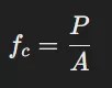
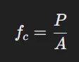
The concrete compressive strength formula is fundamental. It calculates how well concrete can resist axial loads without failing. Concrete compressive strength formula is crucial for determining the strength of concrete structures. It also ensures the durability of buildings, bridges, and roads. The formula for concrete compressive strength is expressed as fc = P/A. Here, P is the applied load. A is the cross-sectional area of the concrete specimen. To ensure accuracy, concrete compressive strength testing methods follow strict guidelines.
These guidelines are provided by codes such as ASTM C39 and IS 456. Concrete compressive strength test procedures focus on assessing strength using concrete cubes or cylindrical specimens. These procedures include detailed acceptance criteria to verify whether the concrete meets the required standards. Additionally, a concrete compressive strength data set can help in evaluating the strength over different curing periods. The standard deviation for concrete compressive strength helps assess consistency and quality.
This article is about the concrete compressive strength formula, concrete compressive strength test IS code etc. This also covers concrete compressive strength acceptance criteria,concrete compressive strength testing methods, standard deviation for concrete compressive strength etc.
Introduction to Concrete Compressive Strength Formula
Concrete Compressive strength testing
The concrete compressive strength formula allows engineers to calculate the ability of concrete to withstand compressive forces. Engineers measure Concrete compressive strength in megapascals (MPa) or Newtons per square millimeter (N/mm²). To determine this strength, engineers apply a compressive force to concrete specimens, such as cubes or cylinders, until the concrete fails. The formula for calculating the compressive strength is
fc = P/A
Where:
fc = Compressive strength (in MPa or N/mm²)
P = Maximum applied load (in Newtons)
A = Cross-sectional area of the specimen (in mm² or cm²)
Engineers worldwide use the concrete compressive strength formula to confirm that concrete can withstand the necessary loads in construction projects.
Code Requirements – Concrete compressive strength
In the construction industry, the concrete compressive strength formula is governed by specific building codes. These codes outline the requirements fortesting of concrete, the selection of appropriate materials, and the acceptance criteria for compressive strength. ASTM C39 is the Standard Test Method for Compressive Strength of Cylindrical Concrete Specimens. IS 456:2000 is the Indian Standard for Code of Practice for Plain and Reinforced Concrete. These standards define the procedures. They also set the acceptable limits for concrete compressive strength.
Adhering to these codes ensures that concrete meets the structural requirements, offering durability and safety in construction. Codes provide specific guidelines on concrete compressive strength testing methods, detailing the use of cubes or cylinders and specifying curing times before testing.
concrete compressive strength testing
Concrete Compressive Strength Test Methods
Testing for concrete compressive strength is a crucial step in the quality control process. Several methods exist, but the most common involves casting concrete specimens (usually cubes or cylinders) and subjecting them to a compressive load. The concrete compressive strength test is typically conducted according to specific standards and includes the following steps:
Sample Preparation: Technicians pour concrete into molds and allow it to cure for a specified period, often 7, 14, or 28 days.
Testing: They place the cured specimen in a testing machine that gradually applies force until the specimen fails. They then record the maximum load.
Calculation: Using the concrete compressive strength formula, they apply the maximum load and cross-sectional area to determine the concrete’s strength.
For cylindrical specimens, the compressive strength of cylindrical concrete specimens formula
Where A is the cross-sectional area of the cylinder (in mm² or cm²). The load is applied along the axis of the cylinder.
Concrete Compressive Strength Data Set
Engineers compile data sets from past concrete test results under various conditions to evaluate the reliability of concrete’s compressive strength. These data sets include information on specimens tested with different curing times, temperatures, and mix compositions, allowing engineers to assess consistency and predict performance trends. These conditions include curing time, aggregate type, water-cement ratio, and cement grade. The data helps engineers make informed decisions about the mix design and predict the likely compressive strength of new batches of concrete.
Compressive Strength of Concrete Cube Formula
The compressive strength of concrete cube formula is similar to that of cylinders. In this case, a concrete cube of standard size (typically 150 mm x 150 mm x 150 mm) is tested. The formula remains
Where P is the applied load, and A is the cross-sectional area of the cube. Cube specimens are used primarily because they are easier to handle and store than cylinders. Their failure pattern is often easier to interpret.
Standard Deviation for Concrete Compressive Strength
When working with concrete, it is important to measure the compressive strength. It is also crucial to evaluate the variability in strength across different batches. Standard deviation is used to assess this variability. A higher standard deviation indicates that the concrete is more inconsistent, which could lead to structural weaknesses. Engineers aim for a low standard deviation to ensure that concrete consistently meets the required strength standards.
The formula for calculating standard deviation for concrete compressive strength is:
Where σ is the standard deviation.
n is the number of test samples, xi is the individual strength value, and x is the mean strength.
Acceptance Criteria
The concrete compressive strength acceptance criteria help in determining if a concrete batch meets the necessary strength. This ensures it is suitable for a given application. These criteria are defined by codes such as ASTM C39 or IS 456 and typically include:
Minimum required compressive strength at 28 days (typically expressed in MPa).
The number of tests needed to assess the batch.
The allowable variation in strength between samples (standard deviation).
If concrete does not meet the acceptance criteria, engineers may reject it or conduct further testing to determine its suitability for use.
Compressive Strength of Concrete: Factors Affecting the Formula
Several factors can influence the concrete compressive strength formula:
Water-Cement Ratio: Lower water-to-cement ratios generally result in stronger concrete.
Aggregate Size and Type: The choice of aggregates affects the strength of the mix.
Curing Conditions: Proper curing ensures that hydration continues and the concrete reaches its maximum potential strength.
Mix Proportions: The specific proportions of cement, water, and aggregates used in the mix design will affect the compressive strength.
Conclusion
The concrete compressive strength formula is a fundamental tool for engineers. It ensures the structural integrity of concrete in construction projects. Engineers follow industry standards and testing methods. They also consider factors such as water-cement ratio and aggregate type. This way, engineers can produce reliable and strong concrete that meets the required safety criteria. Understanding different testing methods is essential. Knowing the concrete compressive strength acceptance criteria is also vital for quality control in the construction industry.
By applying the principles outlined in codes, engineers use comprehensive concrete compressive strength data sets. They can guarantee that concrete will perform as expected under various load conditions. This provides safety and durability in all structures.
Key Takeaways
Testing Methods: Engineers measure concrete strength by testing concrete cubes or cylindrical specimens at various curing periods, typically at 7, 14, or 28 days.
Factors Affecting Strength: Factors such as water-cement ratio, aggregate size, mix design, and curing conditions influence concrete compressive strength.
Acceptance Criteria: The concrete must meet specific strength requirements set by relevant codes. Engineers may reject non-conforming concrete or subject it to additional testing to verify its suitability.
Standard Deviation: Standard deviation is used to assess the variability in compressive strength. A lower deviation indicates more consistent concrete strength, which is vital for ensuring safety.
By understanding the concrete compressive strength formula, engineers can ensure concrete’s reliability. They also consider associated factors to enhance safety and performance in various structural applications.