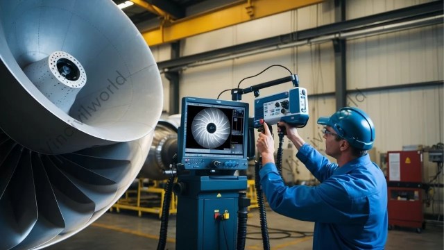
Computed Radiography (CR) is a modern non-destructive testing (NDT) technique that replaces film radiography with a digital imaging process. Computed radiography (CR) does not use traditional X-ray films. Instead, it relies on imaging plates (IPs) to capture high-resolution images. These images are then processed digitally. Consequently, this approach enhances inspection speed, defect detection, and overall image quality. Furthermore, the digital processing ability provides more efficient data storage and analysis.
Computed radiography is widely used in NDT inspections for welds, pipelines, castings, and aerospace components. It eliminates the need for chemical film processing, making it a cost-effective, Eco-friendly, and efficient choice. Additionally, computer radiography allows for faster image analysis, easy digital storage, and seamless sharing for better decision-making.
The transition from film radiography to computerized radiography occurs due to its superior accuracy. This shift also results from reduced operational costs and improved safety standards. This article explains what Computed Radiography means and how it works. It highlights its benefits in NDT inspections. These insights help industries adopt advanced digital testing solutions for better reliability and performance.
- Understanding Computed Radiography
- Role of Computed Radiography in NDT
- Benefits of Computed Radiography in Inspection Services
- Challenges and Limitations of Computed Radiography
- Future Trends and Innovations in Computed Radiography
- Key Takeaways
- Conclusion
Understanding Computed Radiography
Computed Radiography (CR) is an advanced non-destructive testing (NDT) technique that replaces film radiography with a digital imaging system. It uses imaging plates (IPs) instead of traditional X-ray films to capture Radiographic images. Unlike conventional techniques, these plates contain photostimulable phosphors, which store X-ray energy and release it as digital signals during scanning. Moreover, Computerized radiography offers high-resolution images, faster processing, and improved defect detection. As a result, it has become widely used in industries like aerospace, oil and gas, and manufacturing.
The Computed Radiography process involves three key steps:
- Imaging Plates (IPs): These reusable plates store X-ray exposure data when exposed to radiation.
- Scanning Process: A laser scanner reads the plate, converting the stored X-ray energy into a digital signal.
- Digital Image Processing: The signal is transformed into a high-quality digital image that can be analyzed, enhanced, and stored electronically.
Computer radiography is superior to film radiography. It eliminates the need for chemical processing. This makes it a faster, cost-effective, and environmentally friendly solution. CR images can be digitally enhanced, stored, and shared easily, reducing human errors and improving inspection efficiency.
Role of Computed Radiography in NDT
Computed Radiography (CR) plays a vital role in Non-destructive Testing (NDT) by providing high-quality digital imaging for industrial inspections. Moreover, it enhances defect detection, enables real-time assessments, and improves workflow efficiency. As a result, CR has become an essential tool in industries like aerospace, automotive, and infrastructure maintenance. Furthermore, its digital capabilities contribute to better data management and streamlined inspection processes.
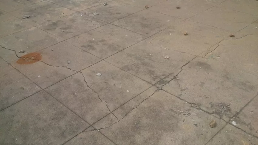
Detection of Defects in Welds, Castings, and Pipelines
Computerized Radiography allows for precise identification of cracks, porosity, voids, and inclusions in welds, castings, and pipelines. The high-resolution digital images enhance flaw visibility, ensuring correct defect evaluation. Advanced contrast adjustments and zooming features improve detection capabilities, reducing the risk of structural failures in industrial applications.
Inspection of Aerospace, Automotive, and Structural Components
Computerized Radiography is widely used in aerospace, automotive, and infrastructure industries to inspect critical components without damaging them. It helps assess engine parts, structural frames, and composite materials, ensuring compliance with safety regulations and industry standards. The ability to digitally enhance and analyse images increases inspection reliability.
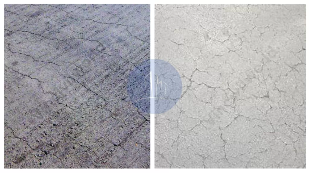
Evaluation of Corrosion and Material Degradation
Computed radiography is effective in assessing corrosion, thinning, and material degradation in metal structures, pipelines, and storage tanks. The digital imaging process provides detailed insights into material conditions, helping engineers decide maintenance requirements and prevent costly failures. This improves the longevity and reliability of industrial assets.
Advantages in Real-Time and Remote Inspections
Computed Radiography technology enables real-time analysis of scanned images, reducing downtime in critical operations. The ability to store and send images digitally allows for remote assessments, expert consultations, and faster decision-making. This is particularly useful in offshore, hazardous, or hard-to-access locations, improving overall inspection efficiency.
Benefits of Computed Radiography in Inspection Services
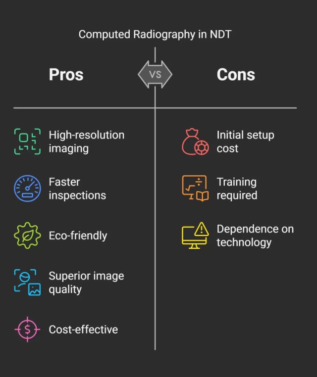
Computed Radiography (CR) revolutionizes Non destructive Testing (NDT) by offering high-resolution digital imaging for defect detection in industrial components. It enhances inspection speed, reduces environmental impact, improves image quality, and enables easy digital storage and sharing. CR provides a cost-effective, efficient, and reliable choice to traditional film radiography.
Defect Detection
Computed Radiography (CR) enhances defect detection by providing high-resolution digital images of welds, castings, and pipelines. It helps find cracks, voids, porosity, corrosion, and inclusions with greater accuracy compared to traditional film radiography. Digital image processing also allows for contrast adjustments and zooming, improving defect visibility for precise evaluation.

Faster Inspections
CR radiography eliminates time-consuming film development by using digital imaging plates (IPs) that are scanned for instant results. This significantly reduces inspection time. It allows for quick decision-making in critical applications. These include pipeline integrity assessments, aerospace inspections, and manufacturing quality control. Faster processing improves workflow efficiency and minimizes downtime in industrial operations.
Eco-Friendly Process
Unlike traditional film radiography, which requires chemical processing and hazardous waste disposal, CR radiography is an eco-friendly solution. It eliminates the use of toxic chemicals, reduces material waste, and lowers environmental impact. The reusable imaging plates (IPs) further contribute to sustainability, making CR an environmentally responsible choice for NDT inspections.
Enhanced Image Quality
Digital CR radiography produces high-contrast, noise-free images with greater dynamic range than traditional film. Advanced image processing tools allow for edge enhancement, contrast adjustments, and noise reduction, improving flaw detection. Inspectors can analyse fine details more effectively. This ensures precise defect evaluation. It also reduces the chances of false positives or missed defects.
Easy Storage & Sharing
CR images are stored in digital formats, eliminating the need for physical film storage. Inspectors can easily retrieve, archive, and share images electronically, allowing for remote analysis and collaboration. Digital storage also enables better documentation, traceability, and compliance with industry standards, improving overall inspection efficiency and record management.
Challenges and Limitations of Computed Radiography
While Computed Radiography (CR) offers many advantages in Non-destructive Testing (NDT), it also presents certain challenges and limitations. These challenges include starting investment costs. Training requirements for operators are also significant. There are sensitivity differences compared to Digital Radiography (DR). Additionally, there is potential for equipment damage and workflow considerations.
Starting Investment Costs for Computed Radiography
Implementing CR systems involves significant initial expenses, encompassing imaging plates, scanners, software, and digital storage solutions. CR reduces ongoing costs linked to film and chemical processing. However, the upfront investment can be substantial. This is particularly true for small and medium-sized enterprises.
Training Requirements for Operators
Transitioning from traditional film-based radiography to CR necessitates specialized training for operators. Skill in digital image acquisition, processing, and interpretation is essential to fully leverage CR’s capabilities. Without adequate training, there is a risk of misinterpreting images or mishandling equipment, compromising inspection quality.
Sensitivity Differences Compared to Digital Radiography (DR)
Computed Radiography systems show lower spatial resolution and sensitivity compared to Digital Radiography systems. This difference can impact the detection of fine defects, making DR more suitable for applications requiring higher precision. Thus, industries with stringent quality standards prefer DR over CR for critical inspections.

Potential for Equipment Damage
CR cassettes and imaging plates are susceptible to damage from mishandling or environmental factors. Scratches, exposure to intense light, or physical impacts can degrade image quality or render the plates unusable. Regular maintenance and careful handling are imperative to preserve equipment longevity and guarantee consistent performance.
Workflow Considerations
CR streamlines certain aspects of the imaging process. Nevertheless, it still requires intermediate steps. These include scanning the imaging plates to digitize images. This process can be more time-consuming compared to DR, which offers immediate image acquisition and viewing. In fast-paced environments where time is critical, the extra processing time linked to CR is a limiting factor.
Understanding these challenges is crucial for organizations. It helps them make informed decisions when selecting appropriate Radiographic techniques. This is essential for their specific NDT applications.
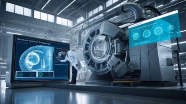
Future Trends and Innovations in Computed Radiography
The field of Computed Radiography (CR) is experiencing significant advancements. These advancements are driven by technological innovations and the integration of artificial intelligence (AI). These developments aim to enhance image quality, streamline workflows, and expand the applications of CR in various industries.
Advancements in Imaging Plate Technology in Computed Radiography
Recent progress in imaging plate (IP) technology focuses on improving detector materials and designs to achieve higher resolution and sensitivity. Innovations include the development of direct conversion detectors. These detectors convert X-rays directly into electrical signals. This process reduces noise and enhances image clarity. These advancements allow more precise defect detection in critical applications like aerospace and automotive industries. Additionally, the use of lightweight, portable detectors enhances the flexibility of CR systems. This portability also improves accessibility, facilitating inspections in remote or confined spaces.
Integration with AI for Automated Defect Detection
The integration of AI into CR systems is revolutionizing defect detection by automating image analysis and interpretation. Machine learning algorithms can be trained to identify patterns in Radiographic images. They can also detect anomalies. This improves diagnostic accuracy and reduces the potential for human error. AI-driven tools, such as Generative Adversarial Networks (GANs) and federated learning, enhance defect detection accuracy. They enable secure, collaborative model training across industries. This integration not only accelerates the inspection process. It also facilitates real-time decision-making. This is crucial in industries where safety and reliability are paramount.
Enhanced Resolution and Faster Scanning Techniques
Efforts to enhance resolution have led to the adoption of advanced imaging techniques. Notably, these efforts also aim to speed up scanning processes. For instance, techniques like phase-contrast radiography and hybrid computed tomography (CT) have been developed. As a result, these methods achieve sub-micron resolution and multi-material analysis, allowing for detailed inspections of complex components. Furthermore, the development of portable systems and autonomous robots equipped with AI and quantum X-ray technology is revolutionizing on-site efficiency. As a result, this advancement paves the way for sub-millisecond defect detection by 2025. Moreover, these innovations are particularly beneficial in infrastructure maintenance. They also aid the manufacturing sector, where rapid and precise inspections are essential.
In summary, the future of Computed Radiography is being shaped by continuous improvements in imaging plate technology. AI integration is also contributing by automating analysis. Additionally, there is a focus on developing high-resolution, fast-scanning techniques. These advancements aim to enhance the efficacy of non-destructive testing. They ensure higher safety standards. This leads to improved operational efficiency across various industries.
Key Takeaways
- Enhanced Defect Detection: Computed Radiography (CR) provides high-resolution digital images. This enables precise identification of internal defects. These include cracks, corrosion, and voids in materials and components.
- Operational Efficiency: The digital nature of CR streamlines the inspection process. It eliminates the need for chemical film development. This change reduces inspection times and increases throughput.
- Environmental Benefits: By removing the need for chemical processing, CR is more environmentally friendly. Disposable films are also eliminated, offering an alternative to traditional Radiographic methods.
- Digital Integration: CR facilitates easy storage, retrieval, and sharing of inspection data, enhancing collaboration and record-keeping within inspection services.
- Technological Advancements: Ongoing innovations in imaging plate technology are continually improving the capabilities of CR. Artificial intelligence is also enhancing the applications of CR in nondestructive testing (NDT).
Conclusion
Computed Radiography has significantly transformed non-destructive testing and inspection services. It offers a digital, efficient, and environmentally conscious choice to traditional film-based radiography. Its ability to deliver high-quality images expedites defect detection and analysis. This process enhances the reliability and safety of critical components across various industries. The shift towards digital solutions not only streamlines workflows but also aligns with modern environmental standards by reducing chemical waste. As technology progresses, CR will continue to improve. Advancements in imaging plate design and artificial intelligence integration will play a key role. They will offer even greater accuracy and efficiency. Embracing these digital innovations is essential for industries. They need to maintain rigorous quality control and safety standards. This is crucial in an increasingly competitive and environmentally conscious market.