For those who spend long hours on the job, lightweight work boots are more than just footwear — they’re essential gear. Whether you’re in construction, electrical work, automotive repair, or any skilled trade, the right boots can significantly enhance comfort, safety, and efficiency. In this guide, we’ll explore what makes light weight work boots so valuable, break down the features you should prioritize, and highlight some top-rated choices that deliver both performance and durability.
Spending all day on your feet takes a toll, especially with heavy boots weighing you down. Traditional work boots can cause quicker exhaustion and discomfort in the legs and feet.
Lightweight options are engineered to combat this issue. With cushioned footbeds, responsive midsoles, and breathable uppers, they help reduce strain and make long shifts more manageable. These features not only improve comfort but also help prevent common foot ailments such as calluses, blisters, and even plantar fasciitis. In the long term, they also reduce your chances of suffering injuries like sprains or muscle strain.
Light boots allow for quicker, easier movement — a huge advantage when navigating busy or tight workspaces. Whether climbing ladders, walking long distances, or crouching frequently, flexibility and mobility are essential.
Modern lightweight boots often use materials like mesh, high-grade nylon, or streamlined leather that maintain toughness without the added weight. Many incorporate anatomical footbeds or flexible soles designed to move naturally with your foot, giving you greater agility on the job.
Boosted Productivity and Job Performance
When your feet feel good, you’re able to concentrate better and maintain your energy throughout the day. Comfortable and mobile boots can lead to fewer breaks, improved focus, and overall higher productivity.
Investing in high-performance lightweight work boots is a smart move for long-term success. You’re not just buying footwear — you’re enhancing your performance, protecting your health, and setting yourself up for a more efficient workday.
What to Look for in Quality Lightweight Work Boots
Durable Yet Light Materials
Lightweight doesn’t mean flimsy. Look for boots constructed from strong yet light materials like engineered mesh, performance leathers, or reinforced nylon. These should be resistant to abrasion and able to stand up to jobsite wear and tear.
Rubber or synthetic outsoles should offer slip and oil resistance while keeping the overall boot weight down. Many models also use shock-absorbing or air-infused midsoles to provide comfort without sacrificing strength.
Protective Toe Options
If your job involves heavy tools or hazardous materials, toe protection is critical. Fortunately, you don’t have to rely on steel toes anymore.
Composite and aluminum toe caps offer excellent protection with much less weight. Composite toes, made from materials like Kevlar, plastic, or carbon fiber, are ideal for non-metallic, non-conductive protection. Aluminum toes are similarly protective but much lighter than traditional steel. Always ensure your safety toe boots meet ASTM standards for impact and compression to ensure compliance and maximum safety.
If you’re often in damp or unpredictable environments, waterproof boots are a must. Seek out models with sealed seams, waterproof membranes, or treated leather uppers to keep moisture out.
Simultaneously, breathability is essential to avoid overheating and sweating inside your boots. Look for shoes with moisture-wicking linings or ventilated uppers to promote air circulation and maintain dryness throughout the workday.
Electrical Hazard (EH) Protection
Those working near live electricity should ensure their shoes offer EH protection. This means the boots are made using non-conductive materials and are tested to resist electrical currents — typically up to 18,000 volts for a minute — as per ASTM F2413 guidelines. Remember, EH-rated boots are an additional precaution, not a substitute for proper electrical safety procedures.
Slip and Oil-Resistant Outsoles
Worksites can present all kinds of surface hazards, from slick oil patches to uneven terrain. A quality lightweight work boot should offer traction-enhancing outsole patterns and slip-resistant rubber compounds. Outsoles made from oil-resistant materials also ensure your boots won’t break down or lose grip prematurely due to chemical exposure.
Recommended Choices: Best Lightweight Work Boots for Men
The Marin (Soft and Composite Toe) – The Marin remains a top-tier option for men needing a lightweight yet durable work boot. Offered in both soft toe and composite toe variations, this 6-inch boot is crafted with barnyard-resistant leather sourced from Texas steer, ensuring both rugged durability and long-term wear. Waterproof and versatile, it’s designed to withstand a variety of tough jobsite conditions without adding bulk.
YURINOX BOOTS UNIONSPACE – The UNIONSPACE boot by YURINOX offers a lightweight, durable option with an ankle-high design and a dual-layer sole made from PU and rubber, providing excellent slip resistance and long-lasting wear. Its black nubuck upper is breathable and water-resistant, while the special lining wicks away sweat to keep feet comfortable all day. Equipped with a composite safety toe for impact protection and a Kevlar puncture-resistant sole to block sharp objects, these boots also resist oil, chemicals, and slips, making them a reliable choice for safety-conscious workers who need agility and comfort on the job.
Every jobsite is different, so think carefully about your work conditions when choosing your boots. Consider how long you’re on your feet, whether you deal with electrical hazards, and if you’re often exposed to water or slippery surfaces.
Try on multiple pairs if possible, and walk around to evaluate comfort and fit. The right boot should provide immediate comfort and meet all your functional and safety requirements. At Yurinox Workwear, we understand the challenges of demanding trades and provide a curated selection of light weight construction boots tailored to meet them. Whether you need waterproof protection, safety toe options, or easy slip-on styles, our range is built to support your performance from the ground up.
Public health engineering helps people to satisfy their humanitarian needs. Today’s crises occur often in urban areas. They usually last longer and have a wider regional effect. They cause widespread human misery, threaten basic services such as water supply and sanitation. Public health engineering is the innovative field dedicated to designing and managing systems for clean drinking water supply, sanitation, waste management, and disease prevention. By integrating environmental engineering with public health, it aims to improve quality of life and community well-being. Key roles include water supply engineering, wastewater management, sanitation infrastructure, and safeguarding against environmental hazards. Public health engineers ensure sustainable practices that address global health and hygiene challenges effectively.
In this blog, I will show what is Public Health Engineering, its learning objectives and the role of a Public Health Engineer.
A clean and balanced Earth is a good place where everyone owns and bears responsibility for ensuring a good quality of life. It can be made possible through several ways.
Some of them are safe drinking water, proper sanitation, and best hygiene practices. This is what Public Health Engineering envisions for our society. It is a specialisation in civil engineering.
A public health engineer conducting water quality testing in an urban environment, highlighting the vital role of engineering in sanitation and water management.
Engineers and technical specialists in the fields of water, sanitation, electricity and other related fields are critical in meeting the challenges and rising demands. They are known as public health engineers.
Water processing, purification, transmission, and distribution are all handled by the Public Health Engineering industry. Thus “Sanitary Engineering” is now referred to as “Public Health Engineering.”
Role of a Public Health Engineer
A public health engineer plays a crucial role in water supply engineering by planning, designing, and maintaining safe systems to deliver clean drinking water supply, ensuring community health and environmental sustainability. Sanitation engineering focuses on designing and managing systems for safe sewage and waste disposal, preventing pollution and disease transmission. It plays a vital role in maintaining community hygiene and protecting public health.
A Public Health Engineer must calculate design flow, design population, design area, and population density in order to do his job. They will play an important role in the present and future scenarios for tackling the following issues:
Now let’s dive deeper into each of the objectives.
Fundamentals of Public Health Engineering:
The first section explores the fundamentals of public health engineering.
It shows how engineers can help reduce mortality and morbidity in a variety of humanitarian situations.
Engineers must have a thorough understanding of how infectious diseases spread in order to do so.
You will be exposed to various disease transmission routes in the area.
You will gain awareness about steps that can be taken to prevent the spread of such diseases.
To aid comprehension, real-life case studies will be presented.
Humanitarian contexts:
The humanitarian background in which public health engineering activities take place is presented in this section. How long-running disputes impact urban basic services like water supply and sanitation, causing public health problems are dealt in this section.
Water Supply Systems:
This section takes a look at some of the most popular water technologies used from the source to the distribution point. We address the benefits and drawbacks of various water distribution systems that can be used.
Sanitation:
The section covers an analysis of sanitation technology and excreta management. Some of the humanitarian sector’s problems and activities are highlighted with the help of case studies.
Waste management & Hygiene promotion:
The section focuses on medical waste. It is a form of solid waste that public health engineers often encounter in humanitarian crises. Finally, in humanitarian emergencies, we address the crucial problem of behaviour modification and hygiene promotion.
A person recycling plastic water bottles, promoting sustainable waste management and hygiene practices.
A career in Civil Engineering with a specialisation in Public Health offers promising prospects. Some career choices that students can explore after their specialisation include:
This Civil Engineering specialisation will place you on the right track if you want to make a difference in combating the global issues. Hope you found this article insightful.
Two basic principle of surveying serves as the cornerstones upon which all other surveying methods are developed. Surveying is the process of determining the relative position of various points on the earth’s surface by measuring the distance between them and creating a map to any reasonable scale. The principle of surveying forms the foundation for accurate land measurement and mapping. Engineers and surveyors apply the first survey principle and second survey principle to ensure precise data collection. A system of reliable control points, established with high precision, anchors the entire survey framework and serves as fixed references for all measurements. Moreover, understanding surveying principles helps professionals establish reliable surveying control points, which are essential for consistent measurements.
Consequently, following these fundamental principles of surveying enables effective planning and execution of surveying projects. By mastering these concepts, surveyors can achieve high accuracy and efficiency in their work, ultimately contributing to successful construction and infrastructure development. Therefore, the principle of surveying and its related key concepts remain critical for the integrity of all surveying activities. In the blog Basic of civil engineering; a Simple and in-depth guide, we saw the fundamentals of surveying. Here, we will look at the fundamental principle of surveying using diagrams to make it easier to understand. So, why follow the surveying principle? Is it unavoidable? Let’s see what happens.
So, why follow the surveying principle? Is it unavoidable? Let’s see what happens.
To understand the importance of the principle of surveying, we should first know the purpose of carrying out surveying. Generally, it is to make measurements of objects on, above, or beneath the ground to show their relative positions on paper. The relative position required is either horizontal, vertical, or both. Or, similarly surveying is used for the measurement of objects in their horizontal positions.
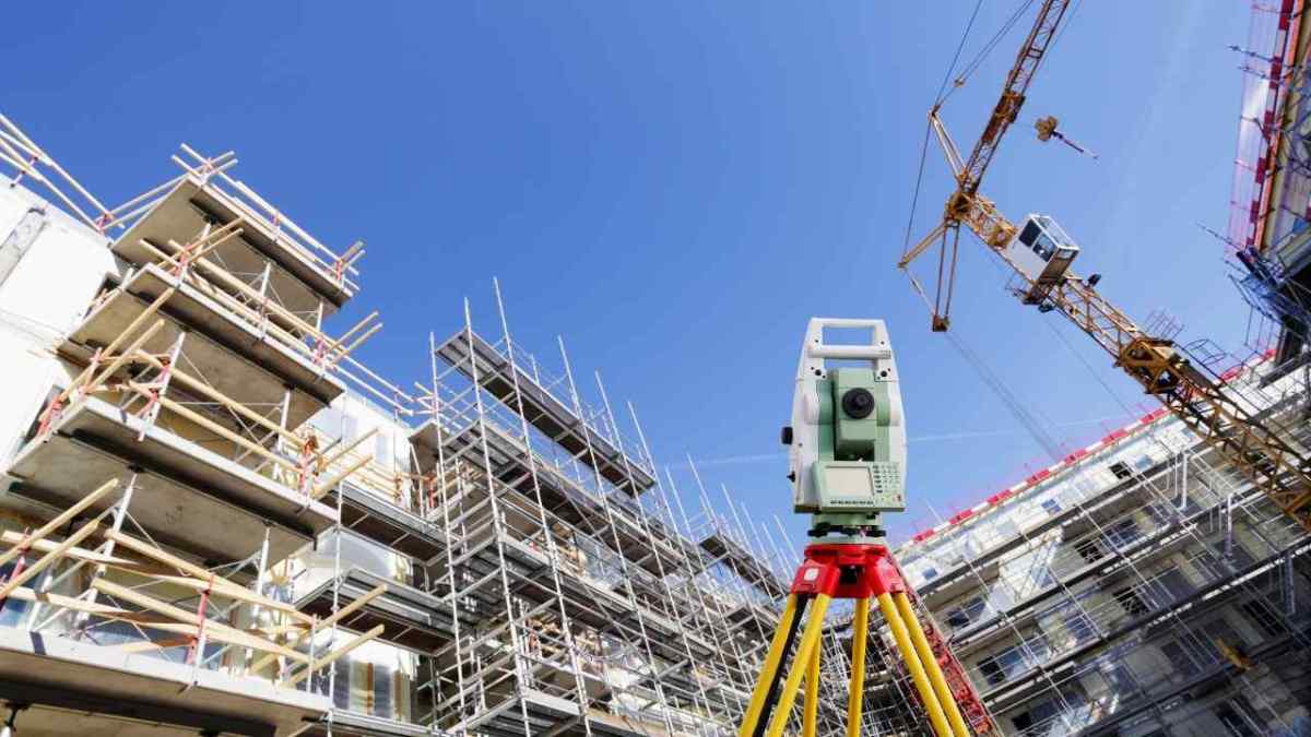
A surveying instrument set up on a construction site, highlighting the importance of accurate measurements in civil engineering.
The principle of surveying comprises two main principles are the strategies to get very accurate results. Basically, successful surveying can’t be carried out without obeying the basic principle of surveying. So, let’s sneak into the details of each of the principles that fetch you accurate results in surveying.
The main principle of surveying is categorized into
First Principle of Surveying
Second Principle of Surveying
The first principle of surveying
The first principle of surveying is to work from whole to part.
To understand this, we should first know what a control point is.
What are control points?
A control point is a point on the ground or any permanent structure whose horizontal and vertical location is known.
Having this in mind, let’s dive deep into the details of the principle.
In surveying large areas, a system of control points is identified and they are located with high precision. Then secondary control points are located using lesser precise methods. Accordingly, the details of the localized areas are measured and plotted concerning the secondary control points. This is called working from whole to part.
Importance of the first principle of surveying
Helps to localize errors to particular points rather than distributing them across the area.
Prevents the accumulation of errors, which can become unacceptable over large areas.
Creates a reliable and accurate control framework before surveying smaller, detailed areas.
Ensures accurate measurements for mapping and construction projects.
Allows secondary control points to be located with less precision while maintaining overall integrity.
Helps contain and adjust inevitable errors within the control framework.
Facilitates efficient surveying by starting from primary control points with high precision and adding subsidiary detail surveys.
Maintains the integrity and precision of surveying data for infrastructure development.
Reduces risk of error magnification during survey.
Supports clear organization of survey work, making it manageable and structured.
These points summarize why the first principle of surveying is critical for achieving quality, reliable, and error-controlled survey outcomes.
Moving on,
The second principle of surveying
Hope you got a clear idea about working from whole to part. Similarly, let us see what the second principle of surveying means.
The second principle of surveying states that new points (stations) must be located by at least two measurements either linear or angular from fixed control points. This redundancy ensures accuracy by verifying positions and minimizing errors. Surveyors use multiple reference points to precisely fix new stations, maintaining reliable mapping and error control throughout the survey process. This principle complements the first principle and is essential for accurate surveying and construction.
Taking extra care in fixing new control points
Taking extra care in fixing new control points
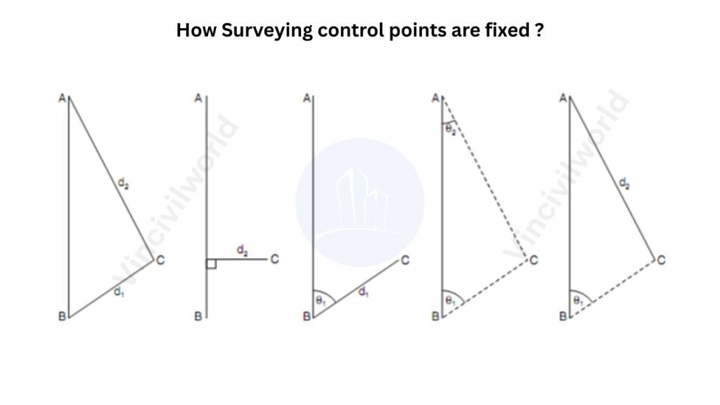
Diagram illustrating the methods of fixing surveying control points with respect to established points A and B.
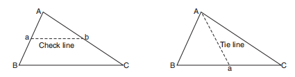
The figure shows the various methods of fixing point C concerning already fixed points A and B by measuring sides, angles, or setting perpendiculars. For fixing new control points (stations) with respect to already fixed points at least two independent processes should be followed.
If A and B are already located control points and concerning the new control point C is to be located, apart from the minimum measurements required as shown in the above figure, one more measurement should be taken.
Measuring the lengths of check lines and tie lines will also serve this purpose as shown in the figure below.
Check line and tie line
Illustration of check lines and tie lines used in surveying to verify measurements and locate points.
So,
what is a check line?
A check line otherwise called a proof line is a line joining the apex of a triangle to some fixed points on any two sides of a triangle. A check line in surveying is the line joining the apex of a triangle to fixed points on its base, used to verify the accuracy of the survey measurements. It ensures correctness by comparing field measurements with plotted lengths, helping detect and control errors. Also called a proof line, it may be run independently to confirm the main survey lines’ precision and sometimes assists in locating interior details.
How check lines are used to check the accuracy of the framework?
The length of checking as measured on the ground should be equal to the length on the plan.Check lines are used to verify the accuracy of a surveying framework by measuring the length on the ground and ensuring it matches the corresponding length on the plan, thereby detecting errors and confirming precision.
Okay. We are done with the check lines. What about tie lines?
What are tie lines?
A tie line joints two fixed points on the main survey lines.
How do tie lines help to embed the principles of surveying?
Tie lines generally, help to check the accuracy of surveying and to locate interior details. The position of each tie line should be close to some features, such as paths, buildings, etc.
Surveyors analyzing construction plans on site while using a total station for precise measurements.
Tie lines, on the other hand, run from the main survey lines. They locate interior or nearby details and avoid long offsets. They connect fixed points (tie stations) and help accurately position details away from main lines, enhancing the survey’s completeness and reducing measurement errors.
So, be happy that you are now savvy in the topic of surveying.
Key Takeaways
The two basic principles of surveying form the foundation of all surveying methods.
Surveying measures relative positions on the Earth’s surface by accurately determining distances and creating maps to scale.
The principle of surveying is essential for precise land measurement, mapping, and infrastructure development.
Engineers use the first principle of surveying to work from the whole to the part, establishing reliable primary control points with high precision.
The second principle of surveying requires locating new points by at least two measurements (linear or angular) from fixed control points to minimize errors.
Control points serve as fixed references, anchoring the survey framework to ensure accuracy and error control.
Check lines verify survey accuracy by comparing ground and plan lengths, while tie lines help locate interior details and maintain survey completeness.
Adhering to these principles ensures efficient, error-controlled, and reliable surveying critical for successful projects.
Conclusion
The principles of surveying are indispensable for achieving accuracy and precision in all surveying tasks within civil engineering. By systematically applying the first principle ,working from broad, reliable control points to detailed measurements and the second principle, using multiple references for new points, surveyors establish a robust control framework that localizes and minimizes errors. Control points anchor this system, ensuring consistent and dependable measurements throughout the survey. Tools like check lines and tie lines further embed these practices by validating measurement accuracy and capturing detailed site information. Mastering these principles fosters efficient planning, mapping, and execution of surveying projects, ultimately supporting high standards in construction and infrastructure development. Thus, surveying principles remain critical for the integrity and success of any surveying activity
Civil construction companies play a crucial role in shaping the built environment across Australia. Their expertise spans a wide variety of projects, both public and private, each requiring specific skills, resources, and regulatory compliance. Understanding the types of projects a civil construction firm can deliver helps in appreciating the breadth and value they bring to infrastructure development.
Public sector civil construction projects are funded and commissioned by local, state, or federal government bodies. These initiatives are often large-scale and aimed at improving community infrastructure, safety, and accessibility.
Transport Infrastructure Civil construction firms are extensively involved in building and upgrading roads, highways, bridges, tunnels, and railways. Projects like the WestConnex motorway in Sydney or the Melbourne Metro Tunnel are prime examples of large-scale public investments delivered by civil contractors.
Water and Sewerage Systems Governments frequently engage a civil construction company for the development and maintenance of water supply and wastewater treatment infrastructure. These include dams, pumping stations, pipelines, and desalination plants, all essential for supporting urban and regional populations.
Public Buildings and Facilities While often associated with vertical construction, civil companies may be contracted for the site preparation and structural components of hospitals, schools, airports, and sporting facilities. Civil works can involve everything from earthmoving and grading to laying foundations and drainage systems.
Parks and Recreational Infrastructure Enhancing liveability in urban areas, councils and state governments invest in parks, pathways, and open spaces. Civil construction is responsible for landscaping, storm water management, and pathway construction within these developments.
Private Sector Projects
Private sector civil construction projects are commissioned by businesses, developers, or private individuals. These projects can range in scale and are usually driven by commercial objectives, timelines, and cost-efficiency.
Residential and Commercial Developments Civil contractors prepare land for housing estates, apartment complexes, and commercial premises. Services include bulk earthworks, road access, utility installation, and stormwater management. These foundational services are critical for enabling vertical construction to proceed safely and efficiently.
Industrial Facilities Mines, factories, logistics hubs, and warehouses often require tailored civil solutions. Construction companies in this space may be tasked with building haul roads, laying heavy-duty pavements, or constructing retaining walls and site drainage systems to support heavy machinery and operations.
Renewable Energy Projects With Australia’s growing investment in renewables, civil firms are increasingly engaged in the construction of wind farms, solar arrays, and battery storage facilities. Their role typically involves site levelling, road access creation, and the installation of cable trenches and foundations.
Private Infrastructure Upgrades Large corporations may contract civil contractors to upgrade internal roads, car parks, or underground services on their campuses or facilities, enhancing safety and capacity.
Whether in the public or private sector, civil construction companies provide the backbone for physical infrastructure in Australia. Their ability to deliver diverse projects—from motorways and water treatment plants to industrial access roads and renewable energy infrastructure, makes them indispensable to national development and economic growth. By leveraging engineering know-how, regulatory understanding, and modern construction methods, these companies continue to shape Australia’s future.
Radiography test is a non-destructive testing (NDT) method. It uses X-rays or gamma rays to examine the internal structure of materials. This technique is essential for detecting hidden flaws without causing damage, ensuring the integrity and safety of components. Radiography test is widely applied in industries such as manufacturing, construction, and aerospace to inspect welding, castings, and structural components. The process involves placing the test object between a radiation source and a detector. An image is captured that reveals internal features. It highlights potential defects. Advancements in digital radiography have enhanced the efficiency and accuracy of these inspections. This process has solidified Radiographic testing as a cornerstone in quality assurance and safety protocols across various sectors.
In this article, we will delve into the principles, techniques, and applications of Radiography test. We’ll explore its significance in non-destructive evaluation, the equipment utilized, and the step-by-step process involved. Additionally, we’ll emphasis on the advantages, limitations, safety considerations, and recent advancements in the field. This comprehensive guide aims to offer a thorough understanding of radiography test and its pivotal role across various industries.
Radiography test is a non-destructive testing (NDT) method. It utilizes X-rays or gamma rays to examine the internal structure of materials. The fundamental principle involves directing radiation through a test object. The radiation is projected onto a detector, like photographic film or a digital sensor. Variations in material density and thickness affect the absorption of radiation. Denser areas absorb more, resulting in lighter regions on the radiography. Meanwhile, less dense areas are darker. This contrast enables the detection of internal flaws like cracks, voids, or inclusions. Radiography test is widely applied across industries. These include aerospace, construction, and manufacturing. This ensures the integrity and reliability of critical components.
RT
In radiography tests, X-rays and gamma rays interact with materials primarily through three mechanisms:
Photoelectric Absorption: Low-energy photons are absorbed by tightly bound electrons, ejecting them from atoms. This effect is more pronounced in materials with higher atomic numbers.
Compton Scattering: Moderate-energy photons collide with loosely bound electrons, resulting in photon deflection and energy loss. This process contributes to image contrast but can also cause image blurring.
Pair Production: High-energy photons (above 1.022 MeV) can transform into an electron-positron pair near a nucleus. This phenomenon becomes significant at higher photon energies.
These interactions cause attenuation of the radiation beam. The degree of attenuation depends on the material’s thickness, density, and atomic number. By analyzing the transmitted radiation, Radiographic testing reveals internal structures and potential defects within the material.
Types of Radiography Tests
Radiography test (RT) is a non-destructive testing method. It employs X-rays or gamma rays to inspect the internal structure of materials. This ensures the integrity and reliability of components across various industries.
Film Radiography
Digital Radiography (DR)
Computed Radiography (CR)
Real-Time Radiography (RTR)
Computed Tomography (CT)
Each of these radiography testing techniques offers unique advantages. The choice among them depends on specific inspection requirements. It also relies on material types and desired image clarity.
Film Radiography test
Film radiography is a traditional non-destructive testing (NDT) method. It effectively utilizes X-rays or gamma rays. These rays inspect the internal integrity of materials and components. In this process, a Radiographic film is placed behind the test object, and radiation is directed through the material. As a result, variations in material density and thickness affect the radiation’s absorption, creating a latent image on the film. Once the chemical processing is complete, this film reveals an image highlighting internal features and potential defects like cracks, voids, or inclusions. Due to its precision, film radiography is renowned for its high-resolution imaging capabilities, making it a reliable choice for detecting even the smallest irregularities. This makes it a preferred choice in industries like aerospace, construction, and manufacturing. Despite advancements in digital radiography, film radiography remains valued for its ability to produce detailed images essential for critical inspections.
Radiography test
Digital Radiography test
Digital Radiography (DR) is an advanced non-destructive testing (NDT) method. It employs digital detectors to capture X-ray or gamma-ray images of a material’s internal structure. Unlike traditional film radiography, DR offers immediate image acquisition and processing, enhancing inspection efficiency and reducing exposure times. This technique provides high-resolution images, facilitating the detection of defects like cracks, voids, and inclusions. Digital Radiography systems also enable easy storage, retrieval, and sharing of digital images, improving workflow and collaboration among inspection teams. Additionally, the Digital Radiography test reduces the need for hazardous chemicals used in film processing. This ultimately promotes a safer and more environmentally friendly work environment. Moreover, its versatility and rapid results have made Digital Radiography testing a preferred choice in various industries, including aerospace, automotive, and oil and gas. In these fields, ensuring the integrity and reliability of critical components is absolutely essential.
Computed Radiography
Computed Radiography (CR) is a modern digital imaging technology that effectively replaces traditional film-based radiography by utilizing photostimulable phosphor (PSP) plates. These advanced plates capture X-ray images efficiently. In this process, the PSP plate is first exposed to X-rays, then stores the image as a latent energy pattern, ensuring accurate and detailed imaging. Subsequently, a laser scanner reads the plate. It releases the stored energy as light. This light is then converted into a digital image for analysis. Computed Radiography offers several advantages over conventional film radiography. These advantages include reduced exposure to radiation and elimination of chemical processing. CR also provides the ability to enhance and digitally archive images. This technology is widely used in medical diagnostics and industrial non-destructive testing, providing a cost-effective and efficient solution for capturing high-quality radiographic images.
Real-Time Radiography test (RTR)
Real-Time Radiography test (RTR) is a non-destructive testing (NDT) technique that enables immediate visualization of an object’s internal structure. X-rays or gamma rays are directed through the test object. They then reach a real-time detector, like a fluorescent screen or digital panel. RTR produces live images and allows for the dynamic observation of components. This immediacy facilitates the detection of defects like cracks, voids, or inclusions during ongoing operations. Real-Time Radiography test (RTR) is widely employed across industries including automotive, aerospace, and electronics. Real-time feedback is crucial in these fields to guarantee part integrity and safety.
Computed Tomography (CT)
Computed Tomography (CT) is an advanced imaging technique that effectively utilizes X-rays to generate detailed three-dimensional representations of an object’s internal and external structures. Unlike traditional methods, the Computed Tomography test captures multiple two-dimensional Radiographic images from various angles. Subsequently, this process reconstructs a comprehensive 3D model, which allows for a thorough examination without causing any damage to the specimen.
Due to its precision and reliability, this non-destructive testing (NDT) method is invaluable across various industries. It is used in aerospace, automotive, and manufacturing and enables precise detection of internal defects. This also allows measurement of complex geometries and verification of material integrity.
Visualizing internal features in high resolution enhances quality control processes. This capability also aids the development of safer and more reliable products. As technology advances, CT continues to evolve. It offers faster scanning times. It also provides improved image clarity. This further solidifies its role as a critical tool in modern NDT practices.
Equipment Used in Radiography Test
Radiographic testing (RT) employs various specialized equipment to inspect the internal structure of materials non-destructively. Essential equipment includes X-ray and gamma-ray sources, detectors, and imaging systems.
Key Equipment Used in Radiographic Testing
Radiation Sources:
X-ray Machines: Generate X-rays using X-ray tubes, commonly employed in medical and industrial applications.
Gamma-ray Sources: Utilize radioactive isotopes like Iridium-192 or Cobalt-60 for material penetration, especially in industrial settings.
Detectors:
Film Radiography: Traditional method using photographic film to capture images after exposure to radiation.
Digital Detectors: Include Computed Radiography (CR) systems with phosphor imaging plates and Digital Radiography (DR) systems with flat-panel detectors for immediate digital imaging.
Image Processing Systems:
Computed Tomography (CT) Scanners: Acquire multiple radiographic images from different angles to create detailed cross-sectional views.
Ancillary Equipment:
Radiation Shielding: Protective barriers and enclosures to safeguard operators from exposure.
Film Processors: Develop exposed films in traditional radiography.
Viewing Stations: Lightboxes or digital monitors for analyzing radiographic images.
The selection of equipment depends on the specific application, material type, and required inspection standards.
Applications of Radiography test
Radiography Testing (RT) is a crucial non-destructive testing (NDT) method widely used across various industries. Specifically, its main purpose is to assess the internal integrity of materials and components. By utilizing X-rays or gamma rays, RT provides detailed images that effectively reveal internal defects. As a result, this method ensures the safety and reliability of critical structures.
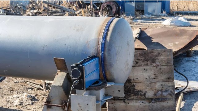
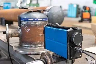
Radiography test for welding
Radiography Test is extensively used to evaluate weld quality in pipelines, pressure vessels, and structural components. It detects defects such as cracks, porosity, and incomplete fusion. Radiography test for welding confirms the weld quality.
Applications of radiography test
Casting Inspection
RT is employed to detect internal defects in metal castings. These defects include shrinkage cavities, gas porosity, and inclusions. This process ensures the structural integrity of cast components.
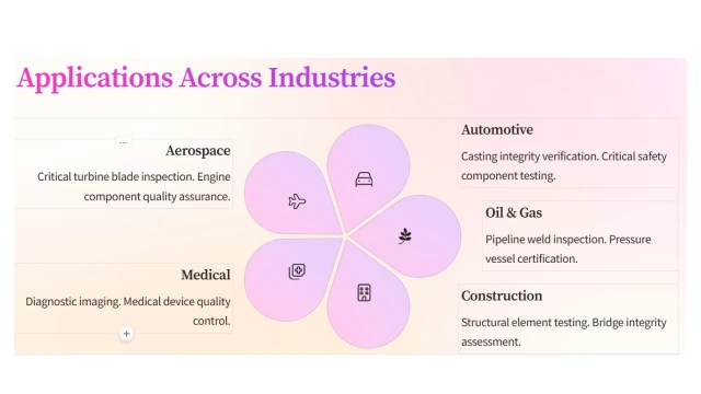
Aerospace Industry
It ensures the integrity of aircraft components, such as turbine blades and structural elements. It does this by identifying internal flaws that compromise safety.
Automotive Sector
Inspects welds, castings, and assemblies to detect defects affecting vehicle performance and safety.
Petrochemical Industry
Examines pipelines, storage tanks, and pressure vessels for corrosion, cracks, and other defects, preventing potential failures.
Manufacturing
Assesses castings, forgings, and other fabricated components to ensure they meet quality standards by detecting internal discontinuities.
Power Generation
Evaluates critical components in nuclear and conventional power plants. This includes reactor vessels and steam generators. These evaluations ensure structural integrity.
Radiography test
Construction
Checks concrete structures and welds in buildings and bridges for internal defects, ensuring structural safety and compliance with regulations.
Radiographic Testing provides a non-invasive means to detect internal flaws. It plays an essential role in maintaining the quality and safety of products. This ensures infrastructure safety across these sectors.
Advantages of Radiography test
Radiographic Testing (RT) is a non-destructive evaluation method. It uses X-rays or gamma rays. These rays inspect the internal structure of materials and components. This technique offers several notable advantages
High accuracy
RT provides precise detection of internal defects. These include cracks, voids, and inclusions. This precision ensures the integrity of critical components. The radiation source size significantly affects Radiographic testing accuracy. A larger source provides more uniform exposure, creating clearer and more accurate images.
Versatility
RT inspects a wide range of materials, including metals, plastics, and composites. Various industries, such as aerospace, manufacturing, and construction, utilize it.
Minimal Material Limitations
RT can be applied to most types of materials. This makes it a versatile choice for inspecting diverse components.
Volumetric Examination
Considered a universal approach to volumetric inspection, RT examines the internal integrity of objects, providing a comprehensive assessment of their condition.
Permanent Inspection Records
RT produces lasting records of inspections, which can be reviewed and referenced for future evaluations, aiding in quality control and compliance documentation.
Sensitivity to Thickness and Density Variations
RT can detect small changes in thickness and density, down to about 1%, along the path of the X-ray beam, allowing for precise identification of defects.
By providing detailed insights into the internal condition of materials without causing damage, Radiographic Testing plays a crucial role in ensuring the safety, reliability, and quality of products and structures across multiple sectors.
Limitations and Safety Considerations of Radiography test
Radiographic Testing (RT) is a valuable non-destructive testing method, but it has several limitations and safety considerations:
Safety Concerns
The use of ionizing radiation poses potential health hazards to personnel. Strict safety measures, including shielding and monitoring, are essential to minimize risks.
High Operational Costs
RT is relatively expensive. This is due to the cost of equipment and materials. It also requires highly trained operators.
Accessibility Requirements
Both sides of the object must be accessible for effective inspection, which can be challenging for certain components.
Complex Geometry Challenges
Specimens with complex shapes may be difficult to inspect accurately using RT.
Detection Limitations
Small, isolated defects less than 2% of the total thickness may not be detected, and defects not aligned with the radiation beam can be challenging to identify.
Health Risks
Exposure to ionizing radiation can lead to severe health issues, including radiation burns and increased cancer risk.
Environmental Impact
Improper handling and disposal of radioactive materials can adversely affect the environment.
Regulatory Compliance
Strict adherence to radiation safety regulations and guidelines is necessary to protect workers and the public.
Addressing these limitations and safety considerations is crucial for the effective and safe application of Radiographic Testing.
Recent Advances in Radiography Test
Radiographic Testing (RT) has experienced significant advancements, enhancing its accuracy, efficiency, and applicability across various industries. Key developments include:
1. Artificial Intelligence (AI) Integration: AI-powered imaging has revolutionized defect detection and analysis in RT. Advanced algorithms, like 3D Generative Adversarial Networks (GANs), synthesize volumetric computed tomography (CT) data. They help multi-angle defect training. This enables real-time augmentation and improves accuracy.
2. Digital Radiography (DR): The transition from traditional film-based systems to DR has led to faster image acquisition. It has also enhanced image quality and reduced radiation exposure. High-resolution flat-panel detectors and direct conversion sensors further improve diagnostic precision.
3. In-Line Computed Tomography (CT): Integrating CT systems directly into production lines allows for real-time inspection and quality control. AI-driven reductions in scan duration make it easier to detect minute defects. These include 30 µm voids in additive-manufactured parts or cracks in turbine blades.
4. Flexible X-Ray Detectors: Innovations like bendable materials capable of wrapping around complex structures have emerged. These flexible detectors enhance inspections in confined or awkward spaces. They are particularly useful in industries like aeronautics. They offer a versatile option to rigid, flat scanners.
5. Enhanced Software Platforms: Modern software developments provide intuitive touch interfaces. For example, the Rhythm RT platform simplifies operation and increases efficiency. These platforms require minimal operator training and maximize the capabilities of portable Radiographic imaging systems.
6. High-Brightness Photon Sources: High-brightness MeV-photon sources are developed based on laser-wake-field accelerators. This development has opened new possibilities for high-resolution radiography of dense, thick objects. Spatial resolutions better than 2.5 line pairs per millimeter at energies in the MeV range have been demonstrated.
These advancements collectively contribute to more precise, efficient, and versatile radiographic testing, ensuring higher quality standards across various applications.
Conclusion
Radiographic Testing (RT) is a cornerstone of non-destructive testing, as it employs X-rays and gamma rays to effectively reveal internal structures. Moreover, this method detects flaws in materials without causing any damage. Due to its reliability, its applications span various industries, including aerospace, automotive, construction, and manufacturing. Ultimately, this ensures the integrity and safety of critical components and structures.
Recent advancements have significantly enhanced RT’s capabilities. The integration of Artificial Intelligence (AI) has revolutionized image analysis, enabling faster and more accurate defect detection. Digital Radiography (DR) has replaced traditional film, offering immediate results and improved image quality. In-line Computed Tomography (CT) systems now facilitate real-time inspections within production lines, boosting efficiency and precision.
Looking ahead, the future of RT is poised for further innovation. The development of portable neutron sources and flexible X-ray detectors promises greater versatility in inspecting complex structures. Enhanced software platforms are streamlining operations, reducing the need for extensive operator training. Additionally, the emergence of high-brightness photon sources is enabling high-resolution imaging of dense objects.
As these technologies evolve, RT will continue to play a pivotal role in quality assurance and safety across industries. Embracing these emerging trends is crucial. Professionals must maintain high standards. They need to adapt to the dynamic landscape of non-destructive testing.
Key takeaways
Radiography Test (RT) is a pivotal non-destructive evaluation method that effectively utilizes X-rays or gamma rays to inspect the internal structure of materials. By doing so, this process ensures the integrity of components across various industries. Some key takeaways include:
Detection of Internal Defects: RT effectively identifies hidden flaws such as cracks, voids, and inclusions, which are not visible on the surface, thereby preventing potential failures. Radiography test for welding can find out weld quality.
Versatile Applications: This technique is widely employed in sectors like aerospace, construction, and manufacturing to assess welds, castings, and structural components.
Permanent Inspection Records: RT provides lasting documentation of inspections, facilitating future reference and quality assurance.
Safety Considerations: The use of ionizing radiation necessitates stringent safety protocols to protect personnel and the environment.
Technological Advancements: Innovations such as digital radiography and computed tomography have enhanced image quality, reduced exposure times, and improved defect detection capabilities.
By understanding these aspects, industries can effectively leverage Radiographic Testing to maintain high-quality standards and ensure operational safety.
Column jacketing strengthens columns and improves their load-carrying capacity. Engineers add materials around existing columns to boost their strength, stiffness, and durability. This method helps repair and upgrade structures to meet modern safety standards. Jacketing of columns increases their resistance to seismic forces, making buildings safer during earthquakes. It also improves the columns’ performance under various loads. Engineers often use concrete jacketing, steel jacketing of columns, and fiber-reinforced polymer (FRP) jacketing for effective strengthening. Concrete jacketing involves applying reinforced concrete around existing columns to enhance their load-bearing capacity and structural integrity. It’s a cost-effective and reliable method for strengthening aging structures.
Column jacketing plays a crucial role in structural engineering. It extends the lifespan of structures and boosts their resilience. Engineers use this technique for strengthening bridges, buildings, and industrial structures. In the next sections, we will talk about the definition, significance, and various techniques of column jacketing.
Jacketing is a structural strengthening method. It involves adding materials around existing structural elements, like columns or beams. This process enhances their strength and durability. It usually involves using reinforced concrete, steel, or fiber-reinforced polymers (FRP). These materials increase the cross-sectional area and structural integrity of the member.
Significance of Jacketing in Structural Engineering
Jacketing is essential for retrofitting and strengthening structures damaged by aging, environmental factors, or increased load demands. It improves the strength and stiffness of structural elements like columns, beams etc., ensuring they meet current safety standards. Jacketing also enhances resilience to seismic forces, making structures safer during earthquakes.
Applications of Jacketing in Retrofitting and Strengthening
Jacketing is commonly used for:
Repairing Deteriorated Structures: Restoring structural integrity damaged by corrosion or environmental factors.
Seismic Retrofitting: Increasing ductility and energy dissipation to resist earthquakes.
Increasing Load Capacity: Upgrading structural members to handle higher loads due to changing building usage.
The jacketing of columns is particularly important for structures located in seismic zones, where enhanced resilience is essential. In the upcoming sections, we will explore various column jacketing techniques and their applications.
Understanding Column Jacketing
Column jacketing is a popular technique used to strengthen and enhance the performance of columns. Engineers use this method to improve load-carrying capacity, stiffness, and durability. The primary purpose of column jacketing is to increase the strength of existing columns. It makes them more resilient against various loads. These loads include seismic forces. It also extends the lifespan of structures and helps them meet modern safety standards. Additionally, column jacketing is a cost-effective solution compared to rebuilding or replacing damaged structures.
Column jacketing is commonly used in several scenarios. Engineers often apply it to structures that show signs of deterioration due to aging or environmental factors. It is also used for retrofitting buildings and bridges to enhance their load-bearing capacity. Moreover, structures located in earthquake-prone areas gain significantly from this technique.
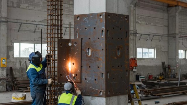
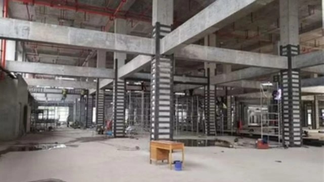
Steel jacketing of column
Overall, column jacketing is a reliable solution for enhancing structural safety and durability. Its effectiveness and versatility make it a preferred choice for repairing, retrofitting, and strengthening various types of structures.
Column Jacketing types
Column jacketing is a structural strengthening technique used to enhance the load-carrying capacity, durability, and seismic resistance of columns. Various techniques are employed based on material type and application requirements. The main types include:
Reinforcement Concrete Jacketing
Steel Jacketing
Fiber Reinforced Polymer (FRP) Jacketing
Carbon Fiber Reinforced Polymer (CFRP) Jacketing
Composite Jacketing
Reinforced Concrete (RC) Column Jacketing
Reinforced Concrete Jacketing is the most common method for strengthening columns. It involves adding a layer of reinforced concrete around the existing column, increasing its cross-sectional area and enhancing its load-carrying capacity. The extra concrete also improves the column’s stiffness, ductility, and resistance to seismic forces. RC Jacketing is widely used for retrofitting old structures and repairing damaged columns. This method is cost-effective and offers excellent fire resistance. However, it requires increased column size, which affects the building’s aesthetics and usable space.
RCC column Jacketing
Working Procedure of Reinforced Concrete Column Jacketing
Surface Preparation: Clean and roughen the existing column surface to improve bonding.
Reinforcement Installation: Place extra reinforcement bars around the column and securely anchor them to the existing column.
Formwork Preparation: Install Formwork around the column, leaving adequate space for the concrete layer.
Concrete Pouring: Pour high-strength or regular concrete into the Formwork and compact it properly.
Curing: Allow the concrete to cure for the required period to achieve desired strength.
Inspection: Remove the Formwork and inspect the finished jacket for defects.
Advantages and disadvantages of Reinforcement Concrete Jacketing
Advantages
Disadvantages
Increases load-bearing capacity.
Increases the size of the column, which reduces usable space.
Enhances ductility and seismic resistance.
Heavyweight affects the structure’s overall weight.
Cost-effective and provides excellent fire resistance.
Requires skilled labor and time for proper implementation.
Widely applicable for retrofitting and repairs.
Steel Jacketing
Steel Jacketing involves encasing columns with steel plates or sections to improve their strength and ductility. This method provides high tensile strength, excellent impact resistance, and increased load-bearing capacity. Steel jacketing is particularly effective for seismic retrofitting and enhancing the structural performance of deteriorated columns. Nevertheless, it needs regular maintenance to prevent corrosion. It is not suitable for environments with high moisture or chemical exposure.
Steel jacketing of columns
Working Procedure of Steel Jacketing of columns
Surface Preparation: Clean the column’s surface to remove dirt, debris, and any loose materials.
Steel Plate Fabrication: Cut steel plates or sections to the required dimensions, ensuring they fit snugly around the column.
Installation of Steel Plates: Position the steel plates around the column. Secure them using bolts or welding. Make sure a tight fit to guarantee effective confinement.
Grouting (if necessary): Inject grout between the steel jacket and the column surface. Fill any gaps. This ensures uniform load transfer.
Corrosion Protection: Apply protective coatings to the steel surface to prevent corrosion and extend the jacket’s lifespan.
Advantages and Disadvantages of steel jacketing of columns
Advantages
Disadvantages
Enhanced Strength and Ductility: Significantly increases the column’s load-bearing capacity and ductility, improving overall structural performance.
Corrosion Susceptibility: Steel is prone to corrosion, especially in humid or aggressive environments, necessitating regular maintenance and protective measures.
Minimal Increase in Cross-Section: Provides significant strength gains without notably increasing the column’s size, preserving architectural aesthetics and usable space.
Cost Considerations: Material and installation costs can be higher compared to other jacketing techniques.
Rapid Installation: The installation process is relatively quick, reducing downtime during retrofitting projects.
Thermal Conductivity: Steel’s high thermal conductivity requires extra fireproofing measures to preserve structural integrity during fires.
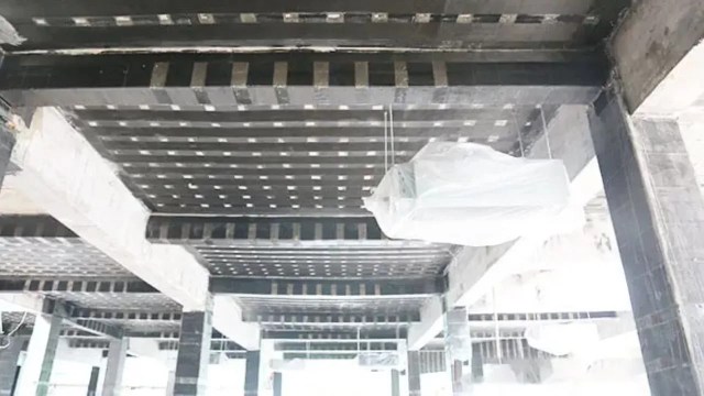
Fiber Reinforced Polymer (FRP) Jacketing
FRP Jacketing uses lightweight, high-strength composite materials. These materials are made of fibers such as carbon, glass, or aramid. They are embedded in a polymer matrix. This method offers superior strength, corrosion resistance, and minimal weight addition to the structure. FRP Jacketing enhances the column’s ductility and load-carrying capacity, making it highly effective for seismic retrofitting. It is easy to install, requires minimal maintenance, and does not significantly alter the appearance of the column. Nonetheless, it is relatively expensive and require additional fire protection measures in certain applications.
Fiber Reinforced polymer(FRP) Jacketing
Working Procedure of Fiber Reinforced Polymer (FRP) Jacketing
Surface Preparation: Clean and smooth the column surface, removing any irregularities to guarantee proper adhesion.
Primer Application: Apply a primer to the prepared surface to promote adhesion between the concrete and the FRP materials.
Resin Application: Coat the primed surface with a layer of resin, serving as the bonding agent for the FRP fabric.
FRP Wrapping: Wrap the resin-coated column with FRP fabric, ensuring proper alignment and tension to remove air pockets.
Extra Resin Coating: Apply another layer of resin over the FRP wrap. This will fully saturate the fibers. It also ensures a strong bond.
Curing: Allow the resin to cure as per the manufacturer’s recommendations, solidifying the FRP jacket.
Advantages and Disadvantages of FRP jacketing
Advantages
Disadvantages
High Strength-to-Weight Ratio: Provides significant strength enhancement without adding considerable weight to the structure.
Cost: FRP materials can be expensive, increasing the overall project cost.
Corrosion Resistance: FRP materials are inherently resistant to corrosion, making them ideal for harsh environmental conditions.
Fire Resistance: FRP materials have limited fire resistance, requiring extra protective measures in fire-prone areas.
Minimal Section Enlargement: The thin profile of FRP jackets preserves the original dimensions of the column, maintaining aesthetics.
UV Sensitivity: Some FRP materials degrade under prolonged UV exposure, necessitating protective coatings for outdoor use.
Ease of Installation: The lightweight and flexible nature of FRP materials facilitates quick and straightforward installation.
Adhesion Sensitivity: Effectiveness heavily relies on proper surface preparation and application techniques.
Carbon Fiber Reinforced Polymer (CFRP) Jacketing
Carbon Fiber Reinforced Polymer (CFRP) Jacketing CFRP Jacketing is a specialized form of FRP Jacketing. It uses carbon fibers for reinforcement. It offers exceptional tensile strength, lightweight properties, and excellent corrosion resistance. CFRP jacketing is widely used for enhancing the seismic resistance and structural performance of columns. It is easy to apply and does not require heavy equipment, making it ideal for structures with limited access. However, CFRP materials are expensive, have poor fire resistance, and are sensitive to ultraviolet light. They are also brittle under certain loading conditions.
Carbon Fiber Reinforced Polymer Jacketing
Working Procedure of Carbon Fiber Reinforced Polymer Jacketing
Surface Preparation: Thoroughly clean and smooth the column surface to ensure optimal adhesion of the CFRP materials.
Primer Application: Apply a suitable primer to the prepared surface. This promotes strong bonding between the concrete and the CFRP materials.
Resin Application: Spread a layer of resin over the primed surface, serving as the adhesive for the CFRP fabric.
CFRP Wrapping: Wrap the resin-coated column with CFRP fabric, ensuring tight wrapping and the elimination of air pockets.
Additional Resin Coating: Apply another resin layer over the CFRP wrap. This will fully saturate the fibers. It will also ensure a robust bond.
Curing: Allow the resin to cure according to the manufacturer’s guidelines, solidifying the CFRP jacket.
Advantages and Disadvantages of Carbon Fiber Reinforced Polymer Jacketing
Advantages
Disadvantages
High Strength-to-Weight Ratio: CFRP offers exceptional strength enhancement with minimal weight addition, preserving structural efficiency.
High Cost: CFRP materials are expensive, significantly increasing project costs compared to other jacketing methods.
Corrosion Resistance: Excellent resistance to corrosion, making it suitable for use in harsh and corrosive environments.
Limited Fire Resistance: CFRP is vulnerable to high temperatures, requiring additional fireproofing measures.
Ease of Installation: Lightweight and flexible nature allows for quick and efficient installation.
Surface Preparation Requirement: Proper surface preparation is essential for effective bonding, demanding meticulous procedures.
Durability and Long Lifespan: CFRP has a long lifespan with minimal maintenance requirements.
UV Sensitivity: Prolonged exposure to ultraviolet rays can degrade the material, requiring protective coatings.
Minimal Section Enlargement: Enhances strength without significantly altering the column’s dimensions, preserving aesthetics.
Brittle Failure Mode: CFRP can exhibit sudden brittle failure without prior warning if overloaded.
Comparison of FRP column Jacketing and CFRP Jacketing
Aspect
FRP Jacketing
CFRP Jacketing
Material Composition
Made of fibers like glass, aramid, or carbon embedded in a polymer matrix.
Specifically made of carbon fibers embedded in a polymer matrix.
Strength
Provides good strength enhancement.
Offers superior strength-to-weight ratio and stiffness.
Weight
Lightweight but heavier than CFRP.
Extremely lightweight and strong.
Corrosion Resistance
High corrosion resistance, especially with glass or aramid fibers.
Excellent corrosion resistance, especially suitable for harsh environments.
Cost
Generally more affordable.
More expensive due to the high cost of carbon fibers.
Application Areas
Suitable for general structural strengthening.
Ideal for high-performance applications requiring exceptional strength and stiffness.
Fire Resistance
Limited fire resistance, require additional protection.
Limited fire resistance, but often better than other FRP types.
Installation
Easy to install due to flexibility.
Slightly more challenging to handle due to stiffness.
Durability
Good durability under most conditions.
Superior durability and long-term performance.
Composite Jacketing
Composite Jacketing Composite Jacketing involves combining different materials, such as steel and FRP, to improve the overall performance of columns. This method provides enhanced strength, ductility, and durability. Composite Jacketing is effective for retrofitting columns exposed to harsh environmental conditions. However, it requires careful material selection and design to achieve the desired performance.
Composite Jacketing
Advantages and disadvantages of Composite Jacketing
Advantages
Disadvantages
Enhanced Strength and Ductility: Combining materials like steel and FRP improves load-bearing capacity and ductility.
Durability: Provides improved resistance to environmental factors like corrosion, impact, and wear.
Higher Cost: Using multiple materials can increase project costs, especially when high-quality materials are used.
Versatility: Suitable for various applications, including seismic retrofitting and rehabilitation.
Installation Complexity: Installation may require specialized skills and techniques for effective application.
Improved Structural Performance: Achieves better overall performance compared to using a single material.
Bonding Issues: Proper bonding between different materials is essential for effective load transfer.
Minimal Aesthetic Impact: Can maintain the original structural appearance when applied properly.
Maintenance Requirements: Require regular inspection and maintenance to ensure continued performance.
Work Procedure for Composite Column Jacketing
Assessment and Design: Inspect the column for damage. Design the composite jacketing system based on structural needs and environmental conditions. Select suitable materials (e.g., Steel + FRP) for compatibility and load requirements. Surface Preparation: Clean the column surface to remove dirt and coatings. Repair cracks or weak spots for a smooth bonding surface. Steel Jacketing (If Applicable): Install steel plates around the column using anchors or bolts. Weld or bolt plates for proper fitting. FRP Jacketing Application: Cut FRP sheets to size. Apply resin or adhesive to the column and sheets. Wrap sheets around the column with proper alignment and overlap. Allow curing. Finishing: Apply protective coating if needed. Inspect for bonding and alignment. Quality Control: Perform NDT or load tests to ensure effectiveness. Regularly inspect and maintain the jacketed columns.
Advantages and Disadvantages of composite column jacketing
Advantages
Disadvantages
High Strength-to-Weight Ratio: CFRP offers exceptional strength enhancement with minimal weight addition, preserving structural efficiency.
High Cost: CFRP materials are expensive, significantly increasing project costs compared to other jacketing techniques.
Corrosion Resistance: Excellent resistance to corrosion, making it suitable for use in harsh and corrosive environments.
Limited Fire Resistance: CFRP is vulnerable to high temperatures, requiring extra fireproofing measures.
Ease of Installation: Lightweight and flexible nature allows for quick and efficient installation.
Surface Preparation Requirement: Proper surface preparation is essential for effective bonding, demanding meticulous procedures.
Durability and Long Lifespan: CFRP has a long lifespan with minimal maintenance requirements.
UV Sensitivity: Prolonged exposure to ultraviolet rays can degrade the material, requiring protective coatings.
Minimal Section Enlargement: Enhances strength without significantly altering the column’s dimensions, preserving aesthetics.
Brittle Failure Mode: CFRP can exhibit sudden brittle failure without prior warning if overloaded.
Applications of Column Jacketing
Seismic retrofitting of buildings.
Strengthening deteriorated or damaged columns.
Upgrading structures to meet new load requirements.
Corrosion protection in harsh environments.
Enhancing fire resistance.
Repairing bridges, industrial structures, and marine facilities.
Preserving historical structures.
Strengthening industrial plants and parking structures.
Reinforcing offshore platforms.
Improving structural performance and durability.
Key Takeaways
Column Jacketing is a structural strengthening technique used to enhance load capacity, durability, and seismic resistance of columns.
Types of Jacketing: Includes Steel Jacketing, Concrete Jacketing, FRP Jacketing, CFRP Jacketing, and Composite Jacketing.
Applications: Widely applied in seismic retrofitting, corrosion protection, industrial structures, bridges, and historical building preservation.
Advantages: Increased strength, durability, corrosion resistance, and fire protection.
Disadvantages: High cost, complex installation, maintenance needs, and potential aesthetic impact.
Work Procedure: Involves assessment, surface preparation, installation, finishing, and quality control.
Quality Control: Non-destructive testing and regular inspection ensure long-term performance.
Best Choice: Selecting the appropriate method depends on structural requirements, environmental conditions, and budget.
Conclusion
Column jacketing is an effective structural strengthening technique that enhances the durability, load-bearing capacity, and seismic resistance of columns. Various methods like Steel, Concrete, FRP, CFRP, and Composite Jacketing offer unique benefits. They also have limitations. It is essential to select the most suitable approach based on specific structural requirements and environmental conditions. Proper assessment, installation, and quality control are crucial to achieving optimal performance. As infrastructure continues to age and face new challenges, column jacketing provides a valuable solution. It aids in the rehabilitation, retrofitting, and protection of critical structural elements.


